| CPC A61F 2/78 (2013.01) [A61F 2/0095 (2013.01); A61F 2/66 (2013.01); A61F 2/76 (2013.01); A61F 2/80 (2013.01); A61F 2002/5056 (2013.01); A61F 2002/7831 (2013.01); A61F 2002/802 (2013.01); Y10T 29/49863 (2015.01)] | 20 Claims |

|
1. A method of fabricating a prosthetic socket, comprising:
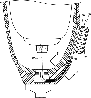
forming a socket comprising a sidewall, a cavity configured to receive a liner, a distal end, and a guide path, wherein the guide path extends proximally from the distal end of the socket;
inserting a tensioning line through the guide path;
coupling a tightening mechanism to the socket, wherein an entire length of the guide path extends within the sidewall from the distal end of the socket to the tightening mechanism;
wherein the tightening mechanism is configured to control movement of the tensioning line such that the tensioning line is configured to draw the liner into the cavity of the socket and towards the distal end of the socket.
|