| CPC A61B 18/1442 (2013.01) [A61B 2018/00053 (2013.01); A61B 2018/0091 (2013.01); A61B 2560/0266 (2013.01)] | 20 Claims |
|
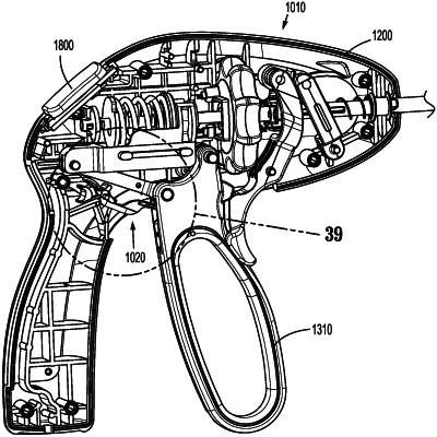
1. A surgical instrument, comprising:
a housing;
an end effector assembly distally-spaced from the housing;
a movable handle operably coupled to the housing and movable relative thereto between an un-actuated position, an actuated position, and an over-actuated position;
a drive assembly operably coupled between the movable handle and the end effector assembly and configured such that movement of the movable handle from the un-actuated position to the actuated position manipulates the end effector assembly; and
a latch assembly operably associated with the housing and the movable handle and configured to lock the movable handle in the actuated position, the latch assembly including:
a latch arm including a latch post extending therefrom; and
a latch track defining a shared path, an entry path, a latching path, a saddle, an un-latching path, and a return path,
wherein the latch post is configured to move through the shared path, the entry path, the latching path, and into the saddle upon movement of the movable handle from un-actuated position through the actuated position to the over-actuated position and back to the actuated position to thereby lock the movable handle in the actuated position, the latch post configured to move within a plane through the shared path, the entry path, the latching path, and into the saddle,
wherein the latch post is configured to move from the saddle through the un-latching path, the return path, and the shared path upon subsequent movement of the movable handle from actuated position to the over-actuated position and back to the un-actuated position, and
wherein the return path includes a ramped surface extending to a cliff that connects the return path with the shared path, the latch post configured to move out of the plane during movement of the latch post along the ramped surface and over the cliff from the return path to the shared path, the cliff configured to inhibit reverse travel of the latch post from the shared path to the return path.
|