| CPC G01P 15/097 (2013.01) [B81B 3/0021 (2013.01); B81B 7/007 (2013.01); G01P 15/125 (2013.01); H10N 30/00 (2023.02); B81B 2201/0235 (2013.01); G01P 2015/0854 (2013.01); G01P 2015/0882 (2013.01); H03H 9/2473 (2013.01)] | 18 Claims |

|
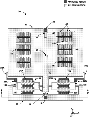
1. An accelerometer device, the device comprising:
a support base that defines a first plane;
a resonator comprising an anchored portion and a released portion, wherein the anchored portion of the resonator mechanically connects to the support base;
a pendulous proof mass mechanically connected to the released portion of the resonator;
one or more damping combs comprising movable comb fingers and anchored comb fingers,
wherein the anchored comb fingers of the one or more damping combs are mechanically connected to the support base,
wherein the movable comb fingers of the one or more damping combs are mechanically connected to the pendulous proof mass, and
wherein a spacing between the movable comb fingers of the one or more damping combs and the anchored comb fingers of the one or more damping combs is configured to provide air damping for the pendulous proof mass;
a resonator connection structure mechanically connected to the support base with an anchor, wherein the resonator connection structure is in a second plane parallel to the first plane;
a hinge flexure configured to connect the pendulous proof mass to the resonator connection structure, wherein the hinge flexure suspends the pendulous proof mass parallel to the support base at the anchor, and wherein the pendulous proof mass rotates about the hinge flexure in the second plane in response to an acceleration of the device parallel to the first plane of the support base,
wherein the resonator is configured to connect the pendulous proof mass to the resonator connection structure and to flex in the second plane based on a rotation of the pendulous proof mass about the hinge flexure,
wherein the pendulous proof mass, the hinge flexure, the resonator connection structure and the resonator are in the second plane, and
a single pressure cavity, wherein the single pressure cavity contains the support base, the resonator, the resonator connection structure, the pendulous proof mass and the one or more damping combs at a same pressure,
wherein the pendulous proof mass includes support flexures with anchor portions and flexible portions, the anchor portions being configured to not exert significant forces on the pendulous proof mass such that the pendulous proof mass is connected to the support base primarily by the anchor and the resonator connection structure is configured such that the resonator connection structure prevents bias errors that result from a thermal expansion mismatch between the support base and the pendulous proof mass and the resonator.
|