| CPC G01N 35/1002 (2013.01) [B01J 19/0093 (2013.01); G01N 2035/1046 (2013.01)] | 3 Claims |

|
1. A system (100) for generating a reagent droplet, said system comprising:
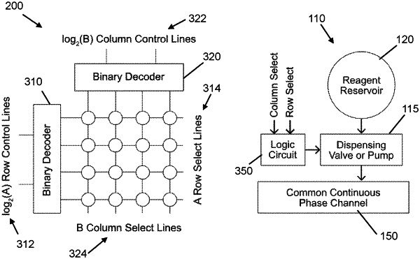
a. an “N” number of droplet dispensers (110) arranged in an array of rows (102) and columns (104), wherein each droplet dispenser (110) comprises a well (120) fluidly coupled to a dispensing valve (115), wherein the well (120) stores a reagent, wherein the dispensing valve (115) is normally closed;
b. a microfluidic logic controller (300) comprising:
i. an “A” number of row-select lines (314), wherein for each row (102) of the array, one row-select line (314) is operatively coupled to the droplet dispensers (110) disposed on said row (102);
ii. a “B” number of column-select lines (324), wherein for each column (104) of the array, one column-select line (324) is operatively coupled to the droplet dispensers (110) disposed on said column (104); and
iii. an “N” number of logic circuits (350), each logic circuit (350) operatively coupled to one dispensing valve (115) such that said logic circuit (350) is configured to actuate the dispensing valve (115), wherein “N”≥1, “A”≥1, and “B”≥1, wherein A×B=N; and
c. a microfluidic channel network (150) configured to have a continuous phase fluid flowing therein, wherein the microfluidic channel network (150) is fluidly coupled to each of the droplet dispensers, wherein the microfluidic channel network (150) is adapted to receive reagent droplets dispensed from the wells (120);
wherein each droplet dispenser (110) is associated with a unique row-column address defined by its row-select line (314) and column-select line (324), wherein each droplet dispenser (110) is operatively coupled to its row-select line (314) and its column-select line (324) via the logic circuit (350) that actuates the dispensing valve (115) only if said logic circuit receives signals from both of the row-select line (314) and the column-select line (324) corresponding to the row-column address of said selected droplet dispenser (110), wherein actuation of the dispensing valve allows for dispensing of a reagent droplet from the well (120) and into the microfluidic channel network (150).
|