| CPC C21D 11/00 (2013.01) [C21D 1/773 (2013.01); C21D 9/0075 (2013.01); C21D 9/525 (2013.01)] | 6 Claims |

|
1. A method for continuous temperature gradient heat treatment of a rod-shaped material using a device,
the device comprising a furnace body, a vacuum pumping equipment, an upper heating power supply and a lower heating power supply, wherein the vacuum pumping equipment, the upper heating power supply and the lower heating power supply are provided outside the furnace body, and wherein
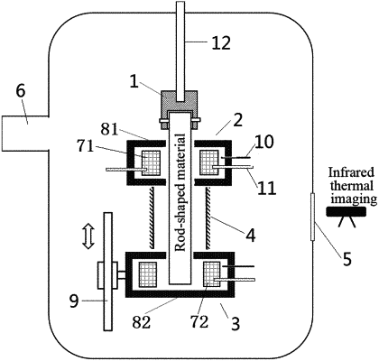
a sidewall of the furnace body is provided with an infrared thermal imaging temperature measuring window (5) and an air outlet (6), and the air outlet (6) is communicated with the vacuum pumping equipment, and
the furnace body is provided with a water-cooling joint (1), an upper heating zone (2), a lower heating zone (3), and an annular radiation screen (4) inside, wherein
the water-cooling joint (1) is fixed onto the top of the furnace body; the annular radiation screen (4) is located between the upper heating zone (2) and the lower heating zone (3), and a distance between the upper end of the annular radiation screen and the bottom of the upper heating zone is in the range of 0-2 mm, and a distance between the lower end of the annular radiation screen and the top of the lower heating zone is in the range of 0-2 mm: the annular radiation screen (4) is provided with a slit with a width of 1-2 mm along an axial direction, and the slit has a length same with that of the annular radiation screen (4), and the infrared thermal imaging temperature measuring window (5) is configured to match with the position of the slit;
the upper heating zone (2) is provided with an upper heating rod (71) and an upper closed heat insulation plate (81), and the lower heating zone (3) is provided with a lower heating rod (72) and a lower closed heat insulation plate (82), wherein the upper heating rod (71) in the upper heating zone (2) is connected to the upper heating power supply, the lower heating rod (72) in the lower heating zone (3) is connected to the lower heating power supply, and the upper closed heat insulation plate (81) and the lower closed heat insulation plate (82) respectively enclose the upper heating rod (71) and the lower heating rod (72) to form closed heating zones, and wherein an upper wall and a lower wall of the upper closed heat insulation plate (81), and an upper wall of the lower closed heat insulation plate (82) are respectively provided with a passage for the rod-shaped material to pass through; and
an axis of the annular radiation screen (4) coincides with an axis of the rod-shaped material and a vertical centerline of the upper heating zone (2) and the lower heating zone (3); the annular radiation screen (4) is not in contact with the rod-shaped material;
the method comprising:
successively passing the rod-shaped material from bottom to top through the upper wall of the lower heating zone (3), the annular radiation screen (4) and the lower wall and the upper wall of the upper heating zone (2), fixing an upper end of the rod-shaped material onto the water-cooling joint (1), and taking a corresponding part of the rod-shaped material that is between the upper heating zone (2) and the lower heating zone (3) as a standard sample section;
vacuuming the furnace body by means of the vacuum pumping equipment, turning on the upper heating power supply and the lower heating power supply, heating a part of the rod-shaped material that is located in the upper heating zone (2) by means of the upper heating rod (71), and heating a part of the rod-shaped material that is located in the lower heating zone (3) by means of the lower heating rod (72), causing heat to be transferred along an axial direction of the rod-shaped material, to form a continuous temperature gradient in the standard sample section of the rod-shaped material, wherein set heating temperatures in the upper heating zone (2) and the lower heating zone (3) respectively correspond to endpoint temperatures of the temperature gradient of the standard sample section of the rod-shaped material; and
measuring a continuous temperature gradient distribution situation of the standard sample section through the infrared thermal imaging temperature measuring window (5), and carrying out thermal insulation when the continuous temperature gradient distribution is stable.
|