| CPC H01R 13/6471 (2013.01) [H01P 3/08 (2013.01); H01R 12/724 (2013.01); H01R 13/66 (2013.01); H05K 1/11 (2013.01)] | 6 Claims |

|
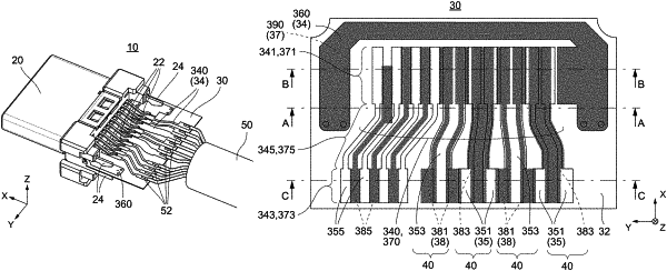
1. A circuit board which is used to connect terminals of a connector to electric wires, wherein:
the circuit board comprises a first layer, a second layer and a dielectric layer;
the dielectric layer is interposed between the first layer and the second layer;
each of the first layer and the second layer is provided with a polarity of trace portions;
each of the trace portions has a connection portion to be connected to the terminal, a wire connection portion to be connected to the electric wire and a line portion connecting between the connection portion and the wire connection portion;
the trace portions of the first layer include two first signal trace portions and a second ground trace portion, the two first signal wiring portions forming a first differential pair;
the first signal trace portions and the second ground trace portion are juxtaposed with each other in a pitch direction;
the trace portions of the second layer include two second signal trace portions and a first ground trace portion, the two second signal wiring portions forming a second differential pair;
the second signal trace portions and the first ground trace portion are juxtaposed with each other in the pitch direction;
in the pitch direction, outer edges of the line portions of the two first signal trace portions are located inward of both edges of the line portion of the first ground trace portion, and outer edges of the line portions of the two second signal trace portions are located inward of both edges of the line portion of the second ground trace portion.
|