| CPC H01M 10/425 (2013.01) [H01M 10/482 (2013.01); H01M 50/209 (2021.01); H01M 50/242 (2021.01); H01M 50/271 (2021.01); H01M 50/284 (2021.01); H01M 50/3425 (2021.01); H01M 50/35 (2021.01); H01M 50/262 (2021.01); H01M 50/289 (2021.01); H01M 50/296 (2021.01); H01M 50/583 (2021.01); H01M 2010/4271 (2013.01); H01M 2200/103 (2013.01); H01M 2220/20 (2013.01)] | 8 Claims |

|
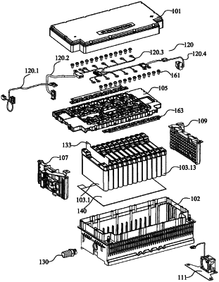
1. A battery pack comprising:
a housing having a bottom portion and side walls extending upward around a periphery of the bottom portion, wherein an upper portion opening is formed at top ends of the side walls;
an upper cover mounted on the upper portion opening of the housing;
multiple battery cells sequentially arranged and mounted in the housing;
a first end plate and a second end plate, wherein the first end plate and the second end
plate are inserted into the housing separately from the multiple battery cells, and wherein the first end plate and the second end plate are located at two end sides of the sequentially arranged multiple battery cells to laterally fix the sequentially arranged multiple battery cells;
a vertical gas discharging passage within the housing on an inner side of a first width side wall; and
a ventilation guide slot in an upper end of the first end plate, the ventilation guide slot forming a middle gas discharging passage located between a lateral gas discharging passage and the vertical gas discharging passage to enable the lateral gas discharging passage to be in fluid communication with the vertical gas discharging passage, wherein the first width side wall is provided with a gas discharging port;
a middle recessed portion formed between protruding battery cell anode and battery cell cathode disposed on a top portion of each of the multiple battery cells, wherein a surface of the middle recessed portion is provided with at least one seal-breakable opening configured to discharge a gas generated in the battery cell when broken, and wherein the middle recessed portions at the top portions of the multiple battery cells form a battery top portion through-slot when the multiple battery cells are sequentially arranged and mounted in the housing;
a bearing plate mounted above the top portions of the multiple battery cells to fix the sequentially arranged and mounted battery cells in a perpendicular direction of the housing, wherein the bearing plate has a bottom-portion through-slot, and a distal end of the bearing plate bottom portion through-slot is provided with a blocking plate so that when the bearing plate is mounted on the top portions of the multiple battery cells, the bearing plate bottom portion through-slot is press-fitted with the battery top portion through-slot to form the lateral gas discharging passage wherein one end of the lateral gas discharging passage is provided with an outlet and another end of the lateral gas discharging passage is blocked.
|