| CPC F25B 41/24 (2021.01) [B60H 1/00278 (2013.01); B60H 1/00885 (2013.01); B60H 1/00921 (2013.01); F25B 41/20 (2021.01); B60H 2001/00307 (2013.01); B60H 2001/00949 (2013.01); B60H 2001/3252 (2013.01)] | 20 Claims |

|
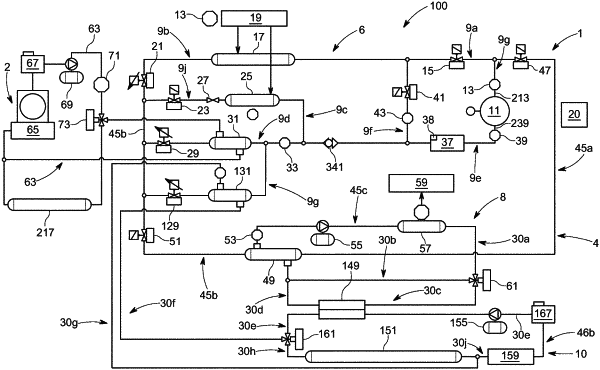
1. A lubricant management system, comprising a vehicle air conditioning circuit comprising a refrigeration cycle refrigerant circuit comprising at least a condenser in thermal communication with a heat source, at least two evaporators each associated with an expansion valve, and a refrigerant compressor, wherein the condenser, the at least two evaporators, the expansion valves and the refrigerant compressor are fluidly connected to one another by a refrigerant line, an accumulator having a lubricant storage capacity and comprising lubricant delivery means, the accumulator being fluidly coupled in the refrigerant line downstream of the at least two evaporators and upstream of the refrigerant compressor,
wherein the at least two evaporators are each fluidly connected in parallel downstream of the condenser and upstream of the accumulator and the associated expansion valves are operable to control a refrigerant flow rate through the at least two evaporators sequentially to flush lubricant from the at least two evaporators to the lubricant storage capacity of the accumulator;
wherein a further expansion valve is associated with the condenser, and wherein the further expansion valve is configured to be throttled to increase the circulation rate of refrigerant mixture to the first or second evaporator to a flushing circulation rate.
|
|
14. A method of lubricant management in an electric vehicle, comprising:
providing the lubricant management system according to claim 1;
operating the refrigerant compressor to initiate a refrigerant mixture circulation in the refrigerant circuit for a selected time period at an operating circulation rate;
closing the expansion valve associated with the first evaporator of the at least two evaporators;
opening the expansion valve associated with the second evaporator of the at least two evaporators;
flushing refrigerant mixture through the second evaporator to flush lubricant trapped in the second evaporator to the accumulator;
opening the closed expansion valve associated with the first evaporator;
closing the open expansion valve associated with the second evaporator; and
flushing refrigerant mixture through the first evaporator to flush lubricant trapped in the first evaporator to the accumulator,
wherein the further expansion valve associated with the condenser is throttled to increase the circulation rate of refrigerant mixture to the first or second evaporator to the flushing circulation rate.
|
|
20. A lubricant management system for use in an electric vehicle that includes a closed loop refrigerant circuit having a condenser, at least two evaporators, at least two evaporator expansion valves, and a refrigerant compressor, wherein each of the at least two evaporator expansion valves is associated with a different one of the at least two evaporators, and wherein the condenser, the at least two evaporators, the at least two expansion valves, and the refrigerant compressor are fluidly connected in the closed loop refrigerant circuit by a refrigerant line that carries a refrigerant through the closed loop refrigerant circuit, wherein the lubricant management system comprises:
a condenser expansion valve associated with the condenser and fluidly connected in the closed loop refrigerant circuit downstream of the condenser and upstream of the at least two evaporators;
an accumulator having a lubricant storage capacity and being fluidly connected in the closed loop refrigerant circuit so as to supply into the refrigerant line a lubricant fluid that combines with the refrigerant in the refrigerant line to thereby form a refrigerant mixture, wherein the accumulator is located downstream of the at least two evaporators and upstream of the refrigerant compressor; and
a controller operably connected to the condenser expansion valve and the at least two evaporator expansion valves;
wherein the at least two evaporators are each fluidly connected in parallel downstream of the condenser and upstream of the accumulator;
wherein the controller is operable in one mode to open all of the at least two evaporator expansion valves and in another mode to close any one or more of the at least two evaporator expansion valves while maintaining at least one other evaporator expansion valve open to thereby provide an increased refrigerant mixture flow rate through one or more evaporators of the at least two evaporators that are associated with an open one of the at least two evaporator expansion valves; and
wherein the condenser expansion valve is configured to be throttled by the controller to control a circulation rate of the refrigerant mixture through the one or more evaporators that are associated with the open one of the at least two evaporator expansion valves.
|