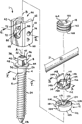
| CPC A61B 17/7035 (2013.01) [A61B 17/7032 (2013.01); A61B 17/7037 (2013.01); A61B 17/7011 (2013.01)] | 21 Claims |

|
13. A pivotal bone anchor assembly configured for implantation in a bone of a patient about a guide wire with a drive tool, and for securing a fixation rod to the bone with a closure configured to apply a downwardly-directed force to lock the assembly, the pivotal bone anchor assembly comprising:
a shank comprising a longitudinal axis, a capture portion at an upper end, an anchor portion opposite the capture portion configured for fixation to the bone, and a neck portion extending between the capture portion and the anchor portion, the capture portion including an upwardly-opening drive socket configured to mate with the drive tool, an upward-facing planar top surface extending perpendicular to the longitudinal axis and surrounding the drive socket, an upper outer curved surface extending downward from the planar top surface, and a lower outer curved surface extending upward from the neck portion, the shank including an axial bore centered about the longitudinal axis and extending distally from the drive socket to a distal tip of the anchor portion and configured to receive the guide wire;
a receiver comprising a base portion defining a central bore centered about a vertical centerline axis and an upper portion integral with the base portion defining a channel configured to receive the fixation rod, the central bore communicating with a bottom of the receiver through a lower opening and extending upward through the channel to a top of the receiver, the central bore including a guide and advancement structure adjacent a top of the receiver configured to mate with the closure and a lower support surface adjacent the lower opening; and
a retainer comprising at least two discrete retainer parts configured for positioning within the central bore of the receiver prior to the capture portion of the shank, each of the retainer parts having an outer surface configured to engage the lower support surface of the receiver and an inner surface configured to capture and hold the capture portion of the shank within the central bore of the receiver so as to prevent the shank from exiting the receiver through the lower opening,
wherein the capture portion of the shank is configured for uploading into the central bore of the receiver through the lower opening with the at least two discrete retainer parts being configured to move at least partially way from each other and then to close toward each other to capture and hold the capture portion of the shank within the central bore of the receiver with the shank extending downward through the lower opening.
|