| CPC H02J 7/35 (2013.01) [H02M 3/1582 (2013.01); H02S 20/32 (2014.12); G05F 1/56 (2013.01); G05F 1/59 (2013.01); G05F 1/595 (2013.01); G05F 1/70 (2013.01); H02M 1/0043 (2021.05); H02M 1/088 (2013.01); H02M 3/01 (2021.05); H02M 3/06 (2013.01); H02M 3/158 (2013.01); H02M 3/33571 (2021.05); H02P 27/08 (2013.01); H02S 40/32 (2014.12); H02S 40/38 (2014.12)] | 20 Claims |
|
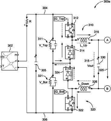
1. A medium-voltage power converter for a photovoltaic (PV) string, the medium-voltage power converter comprising:
a voltage divider having at least two legs, the voltage divider configured to be coupled to the photovoltaic (PV) string;
a first circuit subassembly including a first semiconductor switch and a first semiconductor device coupled together in a cascaded configuration, the first circuit subassembly and a first leg of the at least two legs coupled together in parallel;
a second circuit subassembly including a second semiconductor switch and a second semiconductor device coupled together in a cascaded configuration, the second circuit subassembly and a second leg of the at least two legs coupled together in parallel;
a first inductor having a first end and a second end, the first end coupled between the first semiconductor switch and the first semiconductor device, the second end of the first inductor coupled to a first output terminal;
a second inductor having a first end and a second end, the first end coupled between the second semiconductor switch and the second semiconductor device, the second end of the second inductor coupled to a second output terminal; and
a third circuit subassembly including a third semiconductor switch and a third semiconductor device coupled together, the third circuit subassembly and a third leg of the at least two legs coupled together in parallel.
|