| CPC A61H 1/0288 (2013.01) [A61H 2201/018 (2013.01); A61H 2201/1207 (2013.01); A61H 2201/1463 (2013.01); A61H 2201/5061 (2013.01)] | 8 Claims |
|
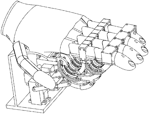
1. A palm-supported finger rehabilitation training device, comprising:
a mounting base, a finger rehabilitation training mechanism mounted on the mounting base, and a driving mechanism for driving the finger rehabilitation training mechanism; wherein the finger rehabilitation training mechanism comprises four independent and structurally identical combined transmission devices configured for finger training corresponding to a forefinger, a middle finger, a ring finger and a little finger of a human hand, respectively, and the mounting base is provided with a supporting surface capable of supporting a human palm; wherein each combined transmission device configured for finger training comprises a metacarpophalangeal (MP) movable chute, a proximal interphalangeal (PIP) fingerstall, a distal interphalangeal (DIP) fingerstall and a connecting rod driving mechanism, wherein:
the MP movable chute is formed by extending along an end of the supporting surface and is an arc structure with a first circular arc chute and a second circular arc chute, wherein the first circular arc chute and the second circular arc chute limit the movement of the connecting rod transmission mechanism;
the connecting rod transmission mechanism comprises a connecting rod a, a connecting rod b, and a connecting rod c; wherein the connecting rod a is provided for connecting a first circular arc chute of the MP movable chute and a transmission arm of the connecting rod b, the connecting rod b is connected with the connecting rod a through a circular arc chute provided in the connecting rod a, and the connecting rod a is positioned proximal the PIP fingerstall, and the connecting rod b is positioned proximal the DIP fingerstall at their respective fingerstall mounting positions; the connecting rod c has a three-section structure comprising a front section, a middle section and an end section connected sequentially, wherein the front section of the connecting rod c is connected with a power output end of the driving mechanism, two ends of the middle section of the connecting rod c are respectively connected with the front section of the connecting rod c and the end section of the connecting rod c, one end of the end section of the connecting rod c is connected with the second circular arc chute of the MP movable chute, and another end is connected with the transmission arm of the connecting rod b; a space sensor is mounted in a middle of the front section of the connecting rod c through a protective housing, and a force sensor is mounted in the DIP fingerstall;
when transmitted by the connecting rod transmission mechanism and driven by the driving mechanism, the PIP fingerstall and the DIP fingerstall have two limit states, a first limit state and a second limit state;
when the PIP fingerstall and the DIP fingerstall are in the first limit state, the PIP fingerstall and the DIP fingerstall are configured to position each finger in the same plane as the human palm;
when the PIP fingerstall and the DIP fingerstall are in the second limit state, the PIP fingerstall and the DIP fingerstall are configured to position each finger to bend inward relative to the human palm;
the driving mechanism comprises four motors disposed in the mounting base, wherein each motor is provided with a motor reduction gearbox mounted in a protective base of the motor reduction gearbox, and a motor encoder.
|