| CPC H04W 56/0035 (2013.01) [H04L 7/0331 (2013.01); H04L 7/06 (2013.01); H04W 56/001 (2013.01)] | 18 Claims |

|
1. A time synchronization method, comprising:
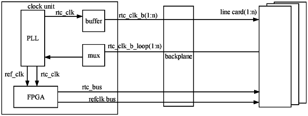
sending a clock synchronization signal and first real time clock (RTC) information separately,
wherein the clock synchronization signal is used to measure a delay between a first module and at least one second module, the delay is used for phase compensation performed on the clock synchronization signal received at the at least one second module, and the clock synchronization signal after being subjected to the phase compensation is used to trigger the at least one second module to update local second RTC information to the first RTC information,
wherein the clock synchronization signal is transmitted between the first module and the at least one second module in a loopback manner, and the transmission in the loopback manner is configured to measure the delay between the first module and the at least one second module, and
wherein the first module comprises a first phase locking loop (PLL) and a logic device,
the first PLL separately sends the clock synchronization signal to the at least one second module and the logic device, and receives the clock synchronization signal looped back by the at least one second module; and
the logic device receives the clock synchronization signal sent by the first PLL, encodes the first RTC information on the clock synchronization signal and sends the encoded first RTC information to the at least one second module.
|