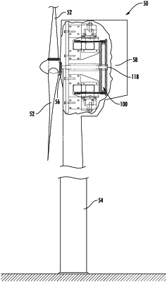
| CPC H02K 21/40 (2013.01) [H02K 7/1807 (2013.01); H02K 7/1838 (2013.01); H02K 21/38 (2013.01); H02K 21/42 (2013.01); Y02E 10/72 (2013.01)] | 6 Claims |

|
1. An electromagnetic generator, comprising:
a first row of flux assemblies, the flux assemblies in the first row having a first coil and a first magnetic field source separated by a first gap;
a second row of flux assemblies, the flux assemblies in the second row having a second coil and a second magnetic field source separated by a second gap;
a third row of flux assemblies, the flux assemblies in the third row having a third coil and a third magnetic field source separated by a third gap;
the flux assemblies in the first row being magnetically and electrically isolated from each other, and offset angularly from the flux assemblies in the second row;
the flux assemblies in the second row being magnetically and electrically isolated from each other, and offset angularly from the flux assemblies in the third row;
the flux assemblies in the third row being magnetically and electrically isolated from each other, and offset angularly from the flux assemblies in the first row;
a shaft; and
a sidewall connected to the shaft and being at least partially positioned inside the first gap, the second gap, and the third gap, and comprising a plurality of magnetic field permeable zones and at least one magnetic field impermeable zone; and
wherein the sidewall is movable in the first gap, the second gap, and the third gap, and relative to the flux assemblies in the first row of flux assemblies, the flux assemblies in the second row of flux assemblies, and the flux assemblies in the third row of flux assemblies to alternatively position the plurality of magnetic field permeable zones and the at least one magnetic field impermeable zone inside the first gap, the second gap, and the third gap.
|