| CPC H02K 1/2766 (2013.01) [B60K 1/00 (2013.01); H02K 2213/03 (2013.01)] | 18 Claims |

|
1. A rotor structure, comprising:
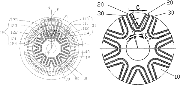
a rotor body, wherein, the rotor body is provided with a magnetic steel slot group; the magnetic steel slot group comprises an outer layer magnetic steel slot; the magnetic steel slot group comprises a plurality of magnetic steel slot segments; and at least two of the plurality of the magnetic steel slot segments are arranged in a radial direction of the rotor body and disposed oppositely on both sides of a direct axis of the rotor body; and
an outer layer permanent magnet, wherein, the outer layer permanent magnet is arranged in the magnetic steel slot segment; a length of the outer layer permanent magnet disposed in two oppositely arranged magnetic steel slot segments is L; a maximum distance between the two oppositely arranged magnetic steel slot segments is C; and 0.8×C≤L;
the magnetic steel slot group further comprises an inner layer magnetic steel slot; the inner layer magnetic steel slot is disposed on an inner side of the outer layer magnetic steel slot and adjacent to the rotating shaft hole;
the rotor structure further comprises an inner layer permanent magnet, and the inner layer permanent magnet is arranged in the inner layer magnetic steel slot;
a fifth included angle α1 is formed between the direct axis of the rotor body and a straight line drawn between a center of the rotor body and a point, at which a side edge of the outer layer permanent magnet adjacent to the direct axis of the rotor body and a surface of the outer layer permanent magnet adjacent to an edge of the rotor body intersect; and a sixth included angle α2 is formed between the direct axis of the rotor body and a straight line drawn between the center of the rotor body and a point, at which a side edge of the inner layer permanent magnet adjacent to the direct axis of the rotor body and a surface of the inner layer permanent magnet adjacent to the edge of the rotor body intersect, wherein, 1.3×(sin α1/sin α2)≤S1/S2≤2×(sin α1/sin α2), S1 denotes a surface area of one side of the outer layer permanent magnet adjacent to the direct axis of the rotor body, and S2 denotes a surface area of one side of the inner layer permanent magnet adjacent to the direct axis of the rotor body.
|