| CPC H01S 5/0683 (2013.01) [H01S 5/0085 (2013.01); H01S 5/02216 (2013.01); H01S 5/02253 (2021.01); H01S 5/02255 (2021.01); H01S 5/0653 (2013.01); H01S 5/0654 (2013.01); H01S 5/0687 (2013.01)] | 17 Claims |

|
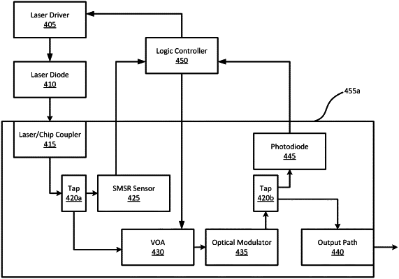
1. A system, comprising:
a laser;
a photodiode;
a Side Mode Suppression Ratio (SMSR) sensor optically connected to the laser;
a Variable Optical Attenuator (VOA) optically connected to the laser;
an optical modulator having an input side connected to the VOA and an output side connected to the photodiode;
a first tap disposed between the laser and both the SMSR sensor and the VOA;
a second tap disposed between the optical modulator and both the photodiode and an output path, wherein the laser is optically connected via a first mirror to a laser/chip coupler, and wherein the laser is optically connected via a second tunable mirror to the first tap; and
a logic controller electrically connected to the laser, the photodiode, the SMSR sensor, and the VOA, configured to adjust a bias of the laser and an attenuation level of the VOA based on an SMSR target, an SMSR reading from the SMSR sensor, and an optical power reading from the photodiode, wherein the logic controller is electrically connected to the second tunable mirror and is configured to tune the second tunable mirror to selectively to reflect a portion of a beam generated by the laser back to the laser.
|