| CPC H01M 8/18 (2013.01) [H01M 8/04298 (2013.01); H01M 8/188 (2013.01); H01M 8/24 (2013.01); H02M 3/33576 (2013.01); Y02E 60/50 (2013.01)] | 6 Claims |

|
1. A flow battery energy storage device, comprising:
a plurality of flow battery units, a plurality of inverters A, a plurality of inverters B, a plurality of inverters C, and a three-phase transformer,
wherein each flow battery unit comprises:
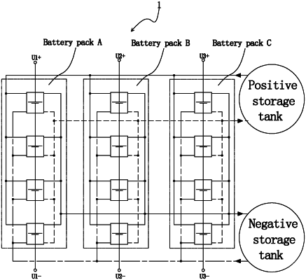
a battery pack A, a battery pack B, a battery pack C, and an electrolyte circulation system connected to the battery pack A, the battery pack B, and the battery pack C,
wherein the battery pack A is coupled to Phase A of the three-phase transformer via a circuit A comprising one of the plurality of inverters A,
wherein the battery pack B is coupled to Phase B of the three-phase transformer via a circuit B comprising one of the plurality of inverters B,
wherein the battery pack C is coupled to Phase C of the three-phase transformer via a circuit C comprising one of the plurality of inverters C,
wherein the circuit A further comprises an isolated DC/DC convertor A or a transformer A, the circuit B further comprises an isolated DC/DC convertor B or a transformer B, and the circuit C further comprises an isolated DC/DC convertor C or a transformer C so that the battery pack A, the battery pack B, and the battery pack C are electrically isolated from one another,
wherein the plurality of inverters A are tandemly connected to form a power unit group A, the plurality of inverters B are tandemly connected to form a power unit group B, and a plurality of inverters C are tandemly connected to form a power unit group C,
wherein the power unit group A is connected to an A phase line and a neutral line of the three-phase transformer, the power unit group B is connected to a B phase line and the neutral line of the three-phase transformer, and the power unit group C is connected to a C phase line and the neutral line of the three-phase transformer, and
wherein an SOC difference among the battery packs A of the plurality of flow battery units is reduced by adjusting a voltage of the AC side of each power unit of the power unit group A; an SOC difference among the battery packs B of the plurality of flow battery units is reduced by adjusting a voltage of the AC side of each power unit of the power unit group B; an SOC difference among the battery packs C of the respective flow battery systems is reduced by adjusting a voltage of the AC side of each power unit of the power unit group C.
|