| CPC G06F 13/382 (2013.01) [G02B 6/4274 (2013.01); G06F 13/4282 (2013.01); G06F 2213/0042 (2013.01)] | 6 Claims |

|
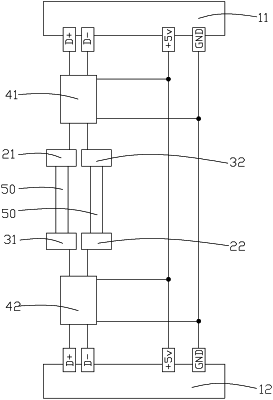
1. A USB 2.0 photoelectric transmission system comprising: a first USB 2.0 connector, a second USB 2.0 connector, a first signal directional interpreting circuit, a second signal directional interpreting circuit, a first laser, a second laser, a first photodetector and a second photodetector,
wherein first and second ends of the first signal directional interpreting circuit are respectively connected to D+ pin and D− pin of the first USB 2.0 connector, third and fourth ends of the first signal directional interpreting circuit are respectively connected to the first laser and the second photodetector, first and second ends of the second signal directional interpreting circuit are respectively connected to D+ pin and D− pin of the second USB 2.0 connector, a third end and a fourth end of the second signal directional interpreting circuit are respectively connected with the second laser and the first photodetector, the first laser and the first photodetector, and the second laser and the second photodetector are connected by optical fibers, the first signal directional interpreting circuit and the second signal directional interpreting circuit are configured to connect the first laser with the D+ pin or the D− pin of the first USB 2.0 connector or the second laser with the D+ pin or the D− pin of the second USB 2.0 connector when it is recognized that there is an electric signal flowing into the D+ pin or the D− pin, and for connecting the first photodetector with the D+ pin or D− pin of the second USB 2.0 connector or connecting the second photodetector with the D+ pin or D− pin of the first USB 2.0 connector when it is recognized that there is an electric signal flowing into the first photodetector or the second photodetector.
|