| CPC G03F 7/709 (2013.01) [G03F 7/70483 (2013.01); G03F 7/70825 (2013.01)] | 22 Claims |

|
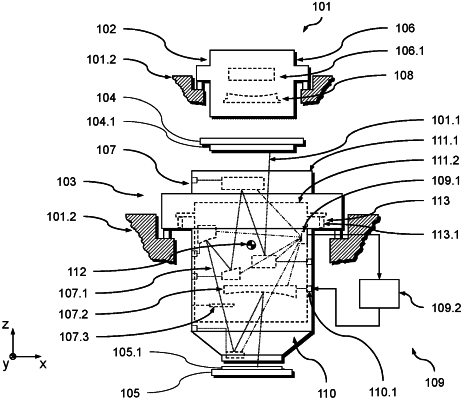
1. An arrangement, comprising:
an optical element;
a first supporting structure supporting the optical element;
a second supporting structure;
a vibration decoupling device comprising a plurality of supporting spring devices;
a measuring device configured to measure a position and/or an orientation of the optical element in relation to a reference in at least one degree of freedom up to all six degrees of freedom in space; and
a creep compensation device configured to compensate a change in a static relative situation between the first and second supporting structures in at least one correction degree of freedom,
wherein:
the first supporting structure supports the second supporting structure via the plurality of supporting spring devices;
the supporting spring devices act kinematically parallel to one another between the first and second supporting structures;
for each supporting spring device, the supporting spring device defines a supporting force direction along which it exerts a supporting force between the first and second supporting structures;
for each supporting spring device, the supporting spring device defines a supporting length along the supporting force direction of the supporting spring device;
the second supporting structure supports the measuring device;
the change in relative situation is due to a change in length of a supporting spring device along its supporting force direction which is due to a creep process of the supporting spring device;
the creep compensation device comprises a controllable active adjustment device;
the controllable active adjustment device comprises an active adjustment element, and at least one of the following holds:
i) the active adjustment device is configured to alter a length of the supporting spring device along the supporting force direction of the supporting spring device, and the active adjustment element is integrated into one of the supporting spring devices; and
ii) the active adjustment device is configured to alter a distance of interfaces of the supporting spring device with the first supporting structure and with the second supporting structure along the supporting force direction of the supporting spring device, and the active adjustment element is integrated into one of the interfaces; and
the arrangement is an arrangement of a microlithographic optical imaging device.
|