| CPC G01R 23/02 (2013.01) | 10 Claims |

|
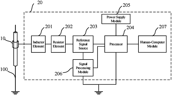
1. A voltage measurement device, comprising a probe module and a measurement unit, wherein the probe module is movably arranged around an outer insulating surface layer of an alternating-current transmission line, a metal electrode is arranged on a surface of the probe module facing toward the alternating-current transmission line, and the measurement unit includes an inductor element, a resistor element, a reference signal source, and a processor; and
wherein the processor is configured to:
determine a plurality of frequencies in a reference frequency range based on a reference step size;
control the reference signal source to input reference voltage signals at the plurality of frequencies to an electrical circuit, the electrical circuit including a coupling capacitor, the inductor element, the resistor element, and the reference signal source, the coupling capacitor being a capacitor formed by electrical coupling between the metal electrode and the alternating-current transmission line;
determine a first current component amplitude, the first current component amplitude being an amplitude of a current component corresponding to a frequency of the alternating-current transmission line in the current of the electrical circuit;
determine second current component amplitudes respectively corresponding to the reference voltage signals at the plurality of frequencies, the second current component amplitudes being amplitudes of current components respectively corresponding to the frequencies of the reference voltage signals in the current of the electrical circuit;
obtain a current amplitude sequence including the second current component amplitudes respectively corresponding to the reference voltage signals at the plurality of frequencies;
determine whether a difference between a first frequency value corresponding to a subsequent current amplitude of a maximum current amplitude in the current amplitude sequence and a second frequency value corresponding to a previous current amplitude of the maximum current amplitude is less than a preset threshold;
determine, when the difference is less than the preset threshold, any one of the first frequency value, the second frequency value, and a frequency value corresponding to the maximum current amplitude as a resonant frequency of the electrical circuit; and
determine, based on the first current component amplitude and the resonant frequency of the electrical circuit, a voltage of the alternating-current transmission line.
|