| CPC G01N 30/20 (2013.01) [G01N 30/468 (2013.01); B01D 15/1821 (2013.01); G01N 2030/201 (2013.01); G01N 2030/205 (2013.01)] | 20 Claims |

|
1. A valve unit for a chromatography apparatus, the valve unit comprising:
a fluid inlet configured to receive an input fluid,
a fluid outlet configured to provide an output fluid,
a first pair of fluid ports comprising a first fluid port and a second fluid port configured to be coupled to a first column,
a second pair of fluid ports comprising a third fluid port and a fourth fluid port configured to be coupled to a second column, and
a coupling valve assembly configured to direct fluid between a selection of the fluid inlet, the fluid outlet, the first pair of fluid ports and the second pair of fluid ports in response to one or more control signals,
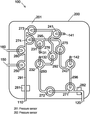
wherein the coupling valve assembly is configured to direct fluid using a selection of membrane valves coupled by fluid channels defined within a body of the coupling valve assembly,
wherein the selection of membrane valves comprises a first membrane valve, a second membrane valve, a third membrane valve, a fourth membrane valve, a fifth membrane valve, a sixth membrane valve, a seventh membrane valve, an eighth membrane valve, a ninth membrane valve, and a tenth membrane valve,
wherein the fluid channels comprise a direct shape following a line having no branches or forks between a start point of the line and an end point of the line, the direct shape being configured to avoid dead, stationary, or stagnant legs,
wherein the first fluid port is coupled to a side port of the first membrane valve, the second fluid port is coupled to a side port of the second membrane valve, the third fluid port is coupled to a side port of the third membrane valve, and the fourth fluid port is coupled to a side port of the fourth membrane valve,
wherein a first fluid channel of said fluid channels connects the fluid inlet to an eleventh membrane valve of a packing fluid port, the seventh membrane valve, the eighth membrane valve and a twelfth membrane valve of a waste fluid port,
wherein a second fluid channel of said fluid channels couples the seventh membrane valve to the tenth membrane valve,
wherein a third fluid channel of said fluid channels couples the tenth membrane valve to the sixth membrane valve,
wherein a fourth fluid channel of said fluid channels couples the sixth membrane valve to the fluid outlet,
wherein a fifth fluid channel of said fluid channels couples the eighth membrane valve to the ninth membrane valve, and
wherein a sixth fluid channel of said fluid channels couples the ninth membrane valve to the fifth membrane valve.
|