| CPC G01N 3/10 (2013.01) [G01N 3/06 (2013.01); G01N 3/02 (2013.01); G01N 3/08 (2013.01); G01N 2203/0003 (2013.01); G01N 2203/0017 (2013.01); G01N 2203/0048 (2013.01); G01N 2203/04 (2013.01); G01N 2203/06 (2013.01)] | 12 Claims |

|
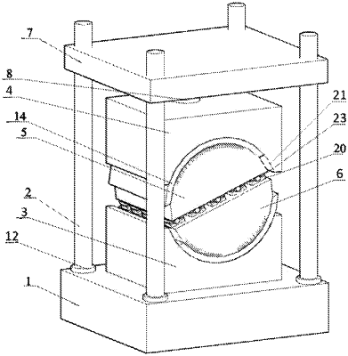
1. A device for testing tensile resistance of multiple-row grouped pillars in an inclined goaf, the device comprising a testing machine base, stands, a lower pressure disk, an upper pressure disk, an upper slideable clamping seat, a lower slideable clamping seat, a transverse frame, protection rings, a hemispherical seat, fixed rings, fixed bolts, arc-shaped clamping blocks, fixed rolling shafts, arc-shaped grooves, upper loading jaws, lower loading jaws, an upper pressing plate, fixed blocks and a force control assembly, wherein
bottoms of the stands are connected with the testing machine base, and tops of the stands are connected with the transverse frame; the upper slideable clamping seat and the lower slideable clamping seat are semi-cylindrical blocks, the lower loading jaws that are positioned to have a same central line are arranged on the lower slideable clamping seat; each of the lower loading jaws is opposite to a corresponding one of the upper loading jaws, the lower loading jaws are welded to the lower slideable clamping seat to test the tensile resistance of samples together; an upper part of the upper slideable clamping seat is connected with the upper pressure disk, and the lower slideable clamping seat is connected with the lower pressure disk; each upper loading jaw of the upper loading jaws and a corresponding one of the lower loading jaws are connected through a directional bearing; and after the each upper loading jaw of the upper loading jaws and the corresponding one of the lower loading jaws are snap-engaged with each other, an elliptical cavity is formed between the each upper loading jaw and the corresponding one of the lower loading jaws, and is used for placing a respective one of the samples, so that eccentric loading of the samples is prevented;
the force control assembly comprises a hydraulic pushing shaft, a hydraulic oil cylinder and pressure sensors; each of the pressure sensors is connected with a microcomputer through a control circuit and is used for accurately controlling a force borne by a corresponding one of the samples; and the hydraulic pushing shaft is controlled and adjusted by the hydraulic oil cylinder, so as to load the samples at a same speed or at different speeds, and to simulate a situation that the samples are subjected to an uniform pressure force and a non-uniform pressure force.
|