| CPC G01N 3/08 (2013.01) [G01N 2203/0017 (2013.01); G01N 2203/04 (2013.01); G01N 2203/0641 (2013.01)] | 7 Claims |

|
1. An in-situ tensile device for X-ray tests, comprising:
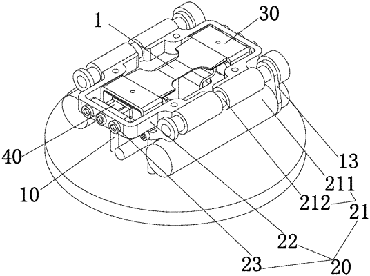
a frame (10), wherein the frame (10) comprises a connecting structure, and the connecting structure is configured to fixedly connect to a testing bench of a testing device;
a stretching mechanism (20), disposed on the frame (10);
a clamping mechanism, comprising two clamping assemblies (30) arranged opposite to each other in a length direction; wherein the two clamping assemblies (30) are configured to clamp two ends of a testing piece (1), the testing piece (1) is provided with a testing surface, and the testing surface is disposed on surfaces of the two clamping assemblies (30); the stretching mechanism (20) is drivingly connected to the two clamping assemblies (30) to enable the two clamping assemblies (30) to move synchronously in one of a direction approaching each other and a direction far away from each other; and the two clamping assemblies (30) are detachably connected to the stretching mechanism (20);
wherein each of the two clamping assemblies (30) comprises:
a supporting part (31), wherein the supporting part (31) is drivingly connected to the stretching mechanism (20);
a clamping part (32), disposed on the supporting part (31); wherein the clamping part (32) is configured to fix the testing piece (1) on the supporting part (31);
wherein the clamping part (32) is sleeved on the supporting part (31), the supporting part (31) is provided with a first top surface and a first bottom surface disposed opposite to each other, a part of the testing piece (1) is located between the first top surface of the supporting part (31) and the clamping part (32), each of the two clamping assemblies (30) further comprises first fasteners (33), and the first fasteners (33) pass through the clamping part (32) and are connected to the first bottom surface of the supporting part (31);
wherein the clamping part (32) is sleeved on a first end of the supporting part (31) close to the other clamping assembly (30);
wherein the stretching mechanism (20) comprises:
driving assemblies (21);
two connecting parts (22), wherein the two connecting parts (22) are connected to the two clamping assemblies (30) in a one-to-one correspondence manner, each of the two connecting parts (22) is detachably connected to a second end of the corresponding supporting part (31) opposite to the first end of the corresponding supporting part (31), and the driving assemblies (21) are drivingly connected to the two connecting parts (22);
wherein each of the two connecting parts (22) comprises a first section (221), a second section (222) and a third section (223) which are sequentially connected; the first section (221) and the third section (223) are located on a same side of the second section (222), and the first section (221) and the third section (223) are configured to connect to the driving assemblies (21); the first section (221), the second section (222) and the third section (223) are arranged around a periphery of the supporting part (31), and the second section (222) is disposed corresponding to the second end of the corresponding supporting part (31); and the stretching mechanism (20) further comprises second fasteners (23), and the second fasteners (23) pass through the two connecting parts (22) and are connected to the supporting parts (31) of the two clamping assemblies (30); and
wherein each of the two connecting parts (22) comprises a second top surface and a second bottom surface disposed opposite to each other, and a height of the second top surface is lower than or equal to a height of the first top surface of the corresponding supporting part (31).
|