| CPC F28D 7/022 (2013.01) [F28D 7/106 (2013.01); F28F 1/36 (2013.01); B33Y 80/00 (2014.12)] | 14 Claims |

|
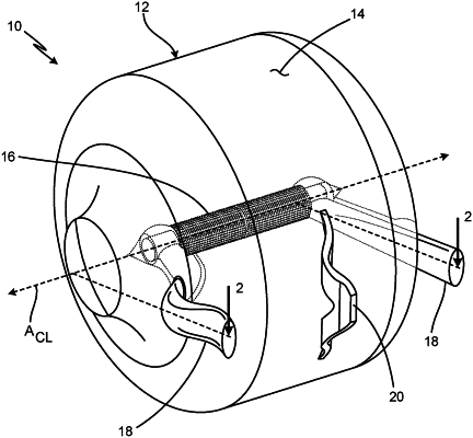
1. A heat exchanger comprising:
a first set of fins that extend radially and that are coaxial with each other, wherein the first set of fins forms a first set of channels;
a second set of fins that extend radially and that are coaxial with each other, wherein:
the second set of fins and the first set of fins form an alternating pattern in a circumferential direction such that each fin of the first set of fins is positioned between two fins of the second set of fins and each fin of the second set of fins is positioned between two fins of the first set of fins; and
the second set of fins forms a second set of channels, wherein channels of the first and second sets of channels are disposed in an alternating pattern in a circumferential direction, wherein the first and second sets of fins are integrally formed together, and wherein a cross-sectional width of a channel in the circumferential direction of at least one of the first set of channels and the second set of channels increases as a radial distance from a centerline axis of the heat exchanger increases;
a curved exterior wall, wherein the first and second sets of fins are contained within the exterior wall;
a first inlet header and a first outlet header, wherein the first inlet header is fluidly connected to and disposed on an upstream end of the first set of fins, and wherein the first outlet header is fluidly connected to and disposed on a downstream end of the first set of fins;
a second inlet header and a second outlet header, wherein the second inlet header is fluidly connected to and disposed on an upstream end of the second set of fins, and wherein the second outlet header is fluidly connected to and disposed on a downstream end of the second set of fins; and
a third inlet header and a third outlet header, wherein the third inlet header is fluidly connected to and disposed on an upstream end of a chamber, and wherein the third outlet header is fluidly connected to and disposed on a downstream end of the chamber.
|