| CPC C03B 17/064 (2013.01) | 10 Claims |

|
1. An apparatus for downwardly drawing a glass ribbon comprising:
a forming vessel comprising:
an upper portion including a pair of outside surfaces that extend parallel to each other, the pair of outside surfaces defining a width of the forming vessel therebetween;
a forming wedge portion including a pair of downwardly inclined forming surfaces converging along a downstream direction to form a bottom edge;
a flow blocking portion that extends alongside the forming wedge;
an edge director comprising:
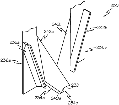
a first flow directing portion formed from an arc portion of a first frustoconical or conical shape that intersects one of the inclined forming surfaces along a first edge of the first flow directing portion and intersects the flow blocking portion along a second edge of the first flow directing portion; and
a second flow directing portion formed from an arc portion of a second frustoconical or conical shape that intersects the other of the inclined forming surfaces along a first edge of the second flow directing portion and intersects the flow blocking portion along a second edge of the second flow directing portion;
wherein an edge director width is no greater than 80 percent of the width of the forming vessel;
wherein the first edges of the first flow directing portion and the second flow directing portion meet at the bottom edge of the forming edge forming an immersion point and an immersion edge; and
wherein the flow blocking portion comprises a channel structure to channel glass toward the first or second flow directing portions, the channel structure extending at an angle on and along a height of the flow blocking portion and being angled toward the immersion edge.
|