| CPC B41F 17/001 (2013.01) [B41M 1/40 (2013.01)] | 15 Claims |

|
1. A printing pad machine having an elongated frame and support assembly comprising:
an engraved print plate having an engraved image thereon and the engraved image is capable of containing and receiving a transferrable ink;
a print fixture plate for supporting a printable product, and having (i) a proximal plate end and (ii) a distal plate end;
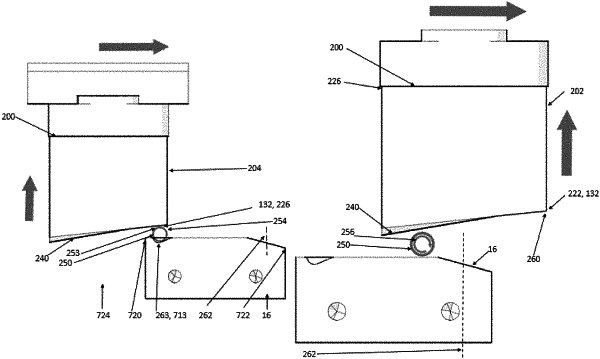
a single angled print pad connected to a base, the single angled print pad has:
a contact wall having a first height,
a lower wall having a second height that is less than the first height,
an angled surface interconnecting the contact wall's distal end and the lower wall's distal end, and
a base wall (a) interconnecting the contact wall's proximal end and the lower wall's proximal end and (b) connectable to the base;
an overhead gantry having a slideably moving support housing capable of moving (i) back and forth between the engraved print plate and the print fixture plate in a first plane, (ii) up and down between the first plane and the engraved print plate when positioned over the engraved print plate, and (iii) up and down between the first plane and the print fixture plate when positioned over the print fixture plate;
a flexion and extension hinge interconnects (a) the base to a slideably moving support housing and (b) the slideably moving support housing to the overhead gantry;
an adjustable and moveable actuator system and power source that
(A) moves the support housing back and forth in the first plane to position the single angled print pad over the engraved print plate,
(B) confirms the base is at least essentially parallel with the engraved print plate or alters the flexion and extension hinge so the base is at least essentially parallel with the engraved print plate;
(C) moves the single angled print pad downward toward the engraved print plate so (i) the contact wall's distal end contacts the engraved print plate prior to the lower wall's distal end and (ii) the angled surface picks up the transferrable ink,
(D) moves the single angled print pad upward toward the first plane;
(E) moves the single angled print pad, in the first plane, toward the print fixture plate,
(F) moves the single angled print pad downward toward the printable product,
(G) alters, between the time frame that the single angled print pad (i) does not contact the engraved print plate during step (D) and (ii) contacts the printable product during step (F), the single angled print pad's configuration through the flexion and extension hinge so the angled surface is at least essentially parallel to the print fixture plate;
(H) moves, depending on the location of the printable product in relation to the single angled print pad, the single angled print pad forward or backward to apply the transferrable ink of an image to the printable product.
|