| CPC A61M 27/006 (2013.01) [A61M 39/22 (2013.01); F16K 99/0023 (2013.01); F16K 99/0042 (2013.01); A61M 2039/226 (2013.01); A61M 2205/3331 (2013.01)] | 18 Claims |

|
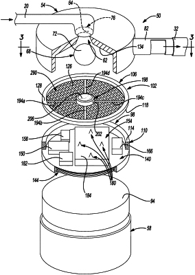
1. A flow and/or pressure regulating assembly for a hydrocephalus shunt system, the regulating assembly comprising:
a reservoir having a reservoir inlet and a reservoir outlet;
a controller;
a valve seat;
a valve member configured to be supported relative to the valve seat to regulate flow into the reservoir through the reservoir inlet; and
an actuator in response to an actuator signal from the controller to move between an active position and an inactive position;
wherein the actuator is selectively positioned in the active position or the inactive position to assist in the valve member regulating the flow into the reservoir;
wherein the actuator comprises:
a first support member;
a second support member; and
an activating system;
wherein the activating system is configured to move the first support member relative to the second support member to raise the second support member or lower the second support member
wherein the first support member is hingedly connected to the second support member;
wherein the second support member is hingedly connected at a fixed position and the first support member is hingedly connected to a pushing arm configured to move the first support member.
|
|
12. A flow and/or pressure regulating assembly for a hydrocephalus shunt system, the regulating assembly comprising:
a valve seat;
a valve member configured to be supported relative to the valve seat to regulate flow into a reservoir;
a support arm member, wherein the support arm member is configured to bias the valve member in a closed position relative to the valve seat;
a substrate positioned on a side of the support arm member away from the valve member; and
a plurality of actuators formed on the substrate and spaced apart along a length of the support arm member, each actuator of the plurality of actuators contacts the support arm member at a different point along the length of the support arm member;
wherein an effective support length of the support arm member determines a biasing force on the valve member and each of the plurality of actuators is configured to be selectively positioned in an active position or an inactive position to select the effective support length;
wherein each of the plurality of actuators is configured to be actuated to contact the support arm member at a plurality of positions along the length of the support arm member to change the effective support length.
|
|
17. A method of configuring a flow and/or pressure regulating assembly for a hydrocephalus shunt system, the method comprising:
positioning a valve member within a reservoir to be biased relative to a valve seat;
supporting and biasing the valve member in a closed position relative to the valve seat with a support arm member;
providing a plurality of actuators on a substrate near the support arm member and spaced apart along a length of the support arm member, each actuator of the plurality of actuators contacts the support arm member at a different point along the length of the support arm member;
configuring each of the plurality of actuators to be selectively positioned in an active position or an inactive position relative to the support arm member to assist in achieving a selected biasing force applied to the valve member; and
selecting an effective support length of the support arm member to achieve the selected biasing force on the valve member, where selecting the effective support length includes configuring each of the plurality of actuators to contact the support arm member at a plurality positions along a length of the support arm member.
|