| CPC A61B 17/320068 (2013.01) [A61B 17/00234 (2013.01); A61B 17/22012 (2013.01); A61B 17/3211 (2013.01); A61B 17/320092 (2013.01); A61B 18/12 (2013.01); A61B 18/1206 (2013.01); A61B 18/1233 (2013.01); A61B 18/14 (2013.01); A61B 18/1442 (2013.01); A61B 18/1445 (2013.01); A61B 17/282 (2013.01); A61B 34/30 (2016.02); A61B 90/361 (2016.02); A61B 2017/0003 (2013.01); A61B 2017/00017 (2013.01); A61B 2017/00022 (2013.01); A61B 2017/00026 (2013.01); A61B 2017/00039 (2013.01); A61B 2017/00061 (2013.01); A61B 2017/00075 (2013.01); A61B 2017/00084 (2013.01); A61B 2017/0084 (2013.01); A61B 2017/00106 (2013.01); A61B 2017/00115 (2013.01); A61B 2017/00137 (2013.01); A61B 2017/00146 (2013.01); A61B 2017/00154 (2013.01); A61B 2017/00199 (2013.01); A61B 2017/00221 (2013.01); A61B 2017/00398 (2013.01); A61B 2017/00464 (2013.01); A61B 2017/00477 (2013.01); A61B 2017/00482 (2013.01); A61B 2017/22014 (2013.01); A61B 2017/2825 (2013.01); A61B 2017/32007 (2017.08); A61B 2017/320073 (2017.08); A61B 2017/320074 (2017.08); A61B 2017/320084 (2013.01); A61B 2017/320094 (2017.08); A61B 2017/320095 (2017.08); A61B 2017/320097 (2017.08); A61B 2018/0063 (2013.01); A61B 2018/00589 (2013.01); A61B 2018/00595 (2013.01); A61B 2018/00601 (2013.01); A61B 2018/00607 (2013.01); A61B 2018/00619 (2013.01); A61B 2018/00648 (2013.01); A61B 2018/00684 (2013.01); A61B 2018/00702 (2013.01); A61B 2018/00791 (2013.01); A61B 2018/00827 (2013.01); A61B 2018/00875 (2013.01); A61B 2018/00886 (2013.01); A61B 2018/00892 (2013.01); A61B 2018/00994 (2013.01); A61B 2018/126 (2013.01); A61B 2018/128 (2013.01); A61B 2018/1253 (2013.01); A61B 2018/1412 (2013.01); A61B 2018/1452 (2013.01); A61B 2034/107 (2016.02); A61B 2090/065 (2016.02); A61B 2090/066 (2016.02); A61B 2090/0808 (2016.02); A61B 2090/0809 (2016.02); A61B 2090/0811 (2016.02); A61B 2217/005 (2013.01); A61B 2218/002 (2013.01); A61B 2218/008 (2013.01)] | 12 Claims |

|
1. A computer-implemented interactive surgical system for controlling an estimated temperature of an ultrasonic blade, the system comprising:
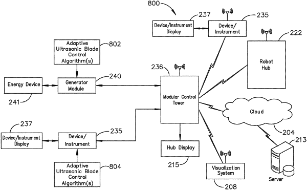
a generator configured to communicate with a modular control tower, the modular control tower in data communication with a modular communication hub, the modular communication hub in data communication with one or more modular devices located in one or more operating theaters of a healthcare facility, the generator comprising a control circuit coupled to a memory, the control circuit configured to:
determine an actual resonant frequency of an ultrasonic electromechanical system comprising an ultrasonic transducer coupled to an ultrasonic blade by an ultrasonic waveguide, wherein the actual resonant frequency is correlated to an actual temperature of the ultrasonic blade;
retrieve from the memory a reference resonant frequency of the ultrasonic electromechanical system, wherein the reference resonant frequency is correlated to a reference temperature of the ultrasonic blade;
infer an inferred temperature of the ultrasonic blade based on a difference between the actual resonant frequency and the reference resonant frequency;
control the estimated temperature of the ultrasonic blade based on the inferred temperature;
generate a temperature estimator and a state space model of the inferred temperature of the ultrasonic blade as a function of the actual resonant frequency of the ultrasonic electromechanical system based on a set of non-linear state space equations;
apply a Kalman filter to improve the temperature estimator and the state space model;
apply a state estimator in a feedback loop of the Kalman filter;
control power applied to the ultrasonic transducer; and
regulate the estimated temperature of the ultrasonic blade,
wherein to determine the actual resonant frequency of the ultrasonic electromechanical system, the control circuit is further configured to determine a phase angle φ between a voltage Vg(t) and a current Ig(t) signal applied to the ultrasonic transducer,
wherein the state space model is defined by:
 wherein:
Fn represents a rate of change of a time (t) dependent natural frequency Fn(t) of the ultrasonic electromechanical system;
T represents a rate of change of the actual temperature of the ultrasonic blade with respect to the time (t) dependent natural frequency Fn(t);
T(t) represents a time (t) dependent actual temperature of the ultrasonic blade;
E(t) represents a time (t) dependent energy;
t represents the time; and
y represents an observability of variables that are measurable and observable including the time dependent natural frequency Fn(t) of the ultrasonic electromechanical system, the time dependent actual temperature T(t) of the ultrasonic blade, observable as the temperature estimator, the time dependent energy E(t) applied to the ultrasonic blade, and time t, and
wherein a state variance of the state estimator of the Kalman filter is defined by:
(σk−)2=σk-1−+σPk2 and
a gain K of the Kalman filter is defined by:
 wherein:
(σk−) is a variance of state k;
(σk-1−) is a variance of the previous state k−1;
(σPk−) is a predicted variance of state k; and
(σm−) is an observed system variance.
|