| CPC A61B 17/151 (2013.01) [A61B 17/1728 (2013.01); A61B 17/1796 (2013.01); A61B 17/80 (2013.01); A61B 90/39 (2016.02)] | 10 Claims |

|
1. A bone plate comprising:
a substantially rigid plate including an elongated body having a proximal end and a distal end and defining a longitudinal body axis;
the plate comprising a bone contacting side, and opposing side, a left sidewall and a right sidewall, all of which extend between the proximal end of the plate and the distal end of the plate and all of which are substantially aligned with the longitudinal body axis;
a proximal elongated slot extending through the plate between the opposing side and the bone contacting side located adjacent to the proximal end of the plate, the proximal elongated slot adapted to receive a bone screw;
a distal elongated slot extending through the plate between the opposing side and the bone contacting side and adjacent to the proximal elongated slot but located distally on the plate relative to the proximal elongated slot, the distal elongated slot adapted to receive a bone screw;
one or more bone screw holes extending through the plate between the opposing side and the bone contacting side and located distally on the plate relative to the distal elongated slot, the one or more screw holes adapted to receive a bone screw;
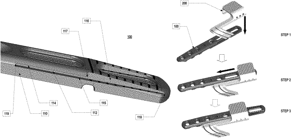
a recess on the opposing side of the plate;
a left track recessed into the left sidewall, the left track extending longitudinally between a track limit point and the proximal end of the plate, the left track being bound by an upper bounding wall, and a lower bounding wall, the lower bounding wall extending for the entire length of the left track while the upper bounding wall extends partially from a distal end of the left track to a location distal to the proximal end of the left track; and
a right track recessed into the right sidewall, the right track extending longitudinally between a track limit point and the proximal end of the plate, the right track being bound by an upper bounding wall, and a lower bounding wall, the lower bounding wall extending for the entire length of the right track while the upper bounding wall extends partially from a distal end of the right track to a location distal to the proximal end of the right track;
wherein portions of the left track and the right track that are bound only by a lower bounding wall provide an overhead entry to the left track and right track accessible from the opposing side of the plate.
|