| CPC A61B 17/0483 (2013.01) [A61B 17/0401 (2013.01); A61B 2017/00743 (2013.01); A61B 2017/0409 (2013.01); A61B 2017/0414 (2013.01); A61B 2017/0417 (2013.01); A61B 2017/0427 (2013.01); A61B 2017/0456 (2013.01); A61B 2017/0464 (2013.01)] | 19 Claims |

|
1. An inserter, comprising:
a hollow elongated shaft extending along a central longitudinal axis and having a proximal end and a distal end with a lumen extending therethrough;
a sharp point at the distal end of the hollow elongated shaft, the sharp point disposed eccentric to the longitudinal axis of the hollow elongated shaft;
a handle at the proximal end of the hollow elongated shaft; and
a drive shaft movably disposed within the lumen of the hollow elongated shaft;
wherein at least one anchor is disposed within the lumen, the at least one anchor attached to a suture, wherein the anchor comprises:
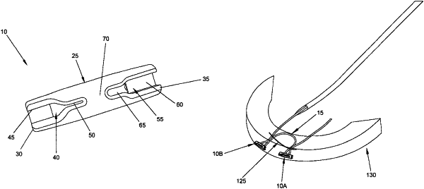
an elongated cylindrical body having a distal end and a proximal end, a longitudinal axis extending between the distal end and the proximal end, and an outer surface offset from the longitudinal axis, the distal end having a distal slot opening on the outer surface of the body and extending from the distal end of the body proximally along the longitudinal axis of the body, and the proximal end having a proximal slot opening on the outer surface of the body and extending from the proximal end of the body distally along the longitudinal axis of the body;
the distal slot comprising a wide section and a narrow section, wherein the wide section has a width configured to slidably accommodate the suture in the wide section and the narrow section has a width configured to bind the suture in the narrow section, and further wherein the wide section is disposed distally of the narrow section.
|