| CPC G01N 3/24 (2013.01) [G01N 33/24 (2013.01); G01N 2203/005 (2013.01); G01N 2203/0025 (2013.01); G01N 2203/0246 (2013.01); G01N 2203/0266 (2013.01)] | 8 Claims |

|
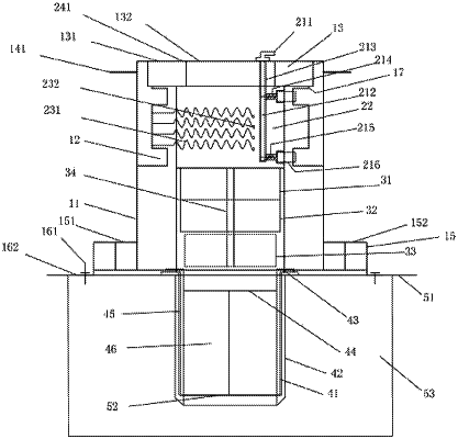
1. An in-situ soil mass shear strength test device, comprising: a casing (11) having a cylindrical body, wherein an upper part of the casing (11) is sleeved and fixed on an upper bearing outer ring (131); a shear core (22), wherein a cylindrical section at an upper part of the shear core (22) is fixed on an upper bearing inner ring (132), and top surfaces of the shear core (22), the casing (11) and an upper bearing (13) are aligned; and a circular force turntable (141), wherein the force turntable (141) is coaxially arranged with the casing (11), and multiple connecting rods (142) are uniformly and fixedly connected therebetween; wherein a lower part of the casing (11) is fixed on a lower bearing inner ring (151), and a lower bearing outer ring (152) is fixed on an anchoring counter-pressure plate (162) under a lower bearing (15); during testing, the anchoring counter-pressure plate (162) is anchored on a surface (51) of a soil mass (53) through anchors (161); at least two columnar protrusions are arranged at a bottom of the shear core (22), and a cavity at a lower portion of the shear core (22) contains, from bottom to top, a rubber plug (33), an electromagnet lower piece (32) and an electromagnet upper piece (31) to apply a pressure on a top surface of a test soil core (46); a connecting straight rod (34) is movably inserted in central through holes of the rubber plug (33), the electromagnet lower piece (32) and the electromagnet upper piece (31); both the connecting straight rod (34) and the electromagnet upper piece (31) are fixed to the shear core (22); adjacent surfaces of the electromagnet upper piece (31) and the electromagnet lower piece (32) have same poles;
the in-situ soil mass shear strength test device further comprises a ratchet mechanism, wherein a ring-like ratchet groove (12) is provided on an internal wall of the casing (11); a right-angled triangle ratchet tooth (216) interacts with the ratchet groove (12), and an acute angle vertex of the ratchet tooth (216) is hinged on the shearing core (22); a ratchet tooth pull rope (215) is fixed between a right-angled vertex of the ratchet tooth (216) and a ratchet tooth reset rod (212); a ratchet tooth spring (214) is sleeved on the ratchet tooth pull rope (215); an outer end of the ratchet tooth spring (214) is fixed on the right-angle vertex of the ratchet tooth (216), and an inner end of the ratchet tooth spring (214) is fixed to a bottom of a cylindrical groove (219) on the shear core (22); the cylindrical groove (219) is arranged radially along the shear core (22); the ratchet tooth reset rod (212) extends into an internal hole (213) of the shearing core from top, and the internal hole (213) is located on an extension line of an axis of the cylindrical groove (219);
multiple force springs (231) are connected between the internal wall of the casing (11) and an external surface of the shear core (22), and when the casing (11) rotates, the force springs (231) are elongated; a dial (241) which quantitatively indicates a torque is fixed on a top surface of the upper bearing outer ring (131), and a reading pointer (242) is fixed on a top surface of the upper bearing inner ring (132);
the in-situ soil mass shear strength test device further comprises a ring knife system to be driven into the soil mass (53) by a force turntable (141) during the testing, wherein an inner ring knife (41) is arranged inside an outer ring knife (42) with a gap therebetween; two vertical shear plates (44), which are perpendicular to each other, are fixed in a cavity of the inner ring knife (41); at least two cylindrical holes for inserting and fixing the columnar protrusions of the shearing core (22) are arranged on a top horizontal edge of the inner ring knife (41).
|