| CPC G01L 25/00 (2013.01) [G01L 1/142 (2013.01); G01L 9/12 (2013.01); G06F 3/044 (2013.01); G06F 3/0418 (2013.01)] | 5 Claims |

|
1. A method for reducing a hysteresis error and a high frequency noise error of capacitive tactile sensors, comprising the following steps:
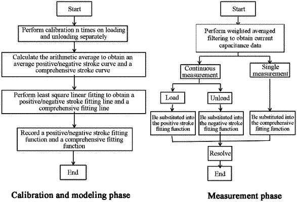
step 1: a calibration, specifically comprising the following steps:
step 1-1: a positive stroke calibration: successively applying m standard loads to a capacitive tactile sensor, wherein the m standard loads gradually increase at a specified step size; forming a loading measurement point each time a standard load is applied; recording a first corresponding standard load value and a first capacitance value at each loading measurement point; and after a loading is completed, fitting first standard load values and first capacitance values of m loading measurement points to form a positive stroke curve;
step 1-2: a negative stroke calibration: successively applying the m standard loads to the capacitive tactile sensor, wherein the m standard loads gradually decrease at the specified step size; forming an unloading measurement point each time the standard load is applied; recording a second corresponding standard load value and a second capacitance value at each unloading measurement point; and after an unloading is completed, fitting second standard load values and second capacitance values of the m unloading measurement points to form a negative stroke curve; and
step 1-3: repeating step 1-1 and step 1-2 n times, wherein n≥3, and n positive stroke curves and n negative stroke curves are formed;
step 2: an averaging, comprising the following steps:
step 2-1: a positive stroke averaging: calculating a first arithmetic average value of n first capacitance values corresponding to the n positive stroke curves formed in step 1 at the each loading measurement point, and recording the first arithmetic average value of each capacitance as a positive stroke average capacitance; obtaining m positive stroke average capacitances at the m loading measurement points; and forming an average positive stroke curve according to the first standard load values of the m loading measurement points and the m positive stroke average capacitances;
step 2-2: a negative stroke averaging: calculating a second arithmetic average value of n second capacitance values corresponding to the n negative stroke curves formed in step 1 at the each unloading measurement point, and recording the second arithmetic average value of each capacitance as a negative stroke average capacitance; obtaining m negative stroke average capacitances at the m unloading measurement points; and forming an average negative stroke curve according to the second standard load values of the m unloading measurement points and the m negative stroke average capacitances;
step 2-3: a comprehensive averaging: calculating a third arithmetic average value of the n positive stroke capacitance values and the n negative stroke capacitance values at a certain standard loading measurement point, and recording the third arithmetic average value as a comprehensive stroke average capacitance; obtaining m comprehensive stroke average capacitances at m standard loading measurement points; and forming a comprehensive stroke curve according to the m standard loads and the m comprehensive stroke average capacitances;
step 3: a fitting modeling: separately performing a least square fitting on the average positive stroke curve, the average negative stroke curve, and the comprehensive stroke curve formed in step 2, to obtain a positive stroke fitting function Fp, a negative stroke fitting function Fn, and a comprehensive fitting function Fave;
step 4: a measurement: using the capacitive tactile sensor calibrated in step 1 to perform an actual measurement, to obtain several measurement capacitance data;
step 5: a noise filtering: performing a weighted average filtering on the measurement capacitance data obtained in step 4, to obtain a filtered capacitance value;
step 6: a stroke direction discrimination: if it is a continuous measurement mode in step 4, comparing the filtered capacitance value at a current time with the filtered capacitance value at a previous time, to determine whether a current measurement mode is a loading stroke or an unloading stroke; or if it is a single measurement mode in step 4, directly performing step 7; and
step 7: a resolving: if a discrimination result in step 6 is the loading stroke, substituting the filtered capacitance value at the current time into the positive stroke fitting function Fp in step 3 to obtain the a force at the current time; if the discrimination result is the unloading stroke, substituting the filtered capacitance value at the current time into the negative stroke fitting function Fn, in step 3 to obtain the force at the current time; or if the discrimination result is the single measurement mode, substituting the filtered capacitance value at the current time into the comprehensive fitting function Fave; in step 3 to obtain the force at the current time.
|