| CPC F02F 1/4285 (2013.01) [F02B 37/025 (2013.01); F02C 6/12 (2013.01); F02C 7/06 (2013.01); F02C 7/36 (2013.01); F02F 7/0002 (2013.01); F05D 2220/40 (2013.01); F05D 2240/50 (2013.01); F05D 2240/60 (2013.01)] | 7 Claims |

|
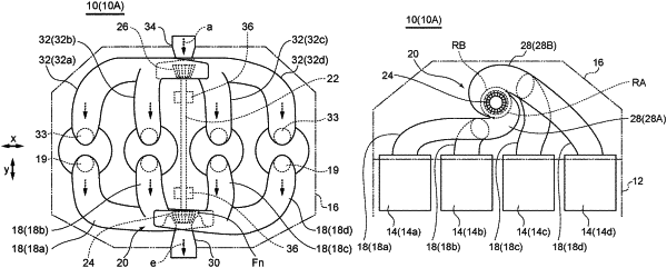
1. An internal combustion engine with a turbocharger, comprising:
a cylinder block internally including a plurality of cylinders;
a cylinder head disposed on top of the cylinder block, and internally including a plurality of exhaust flow passages through which an exhaust air discharged from each of the plurality of cylinders flows; and
the turbocharger including a rotational shaft, a turbine wheel, and a compressor wheel, the turbine wheel being disposed at one end of the rotational shaft, the compressor wheel being disposed at the other end of the rotational shaft,
wherein at least the turbine wheel of the turbocharger is arranged inside the cylinder head, and
wherein the cylinder head internally includes a plurality of scroll passages for introducing the exhaust air flowing through the plurality of exhaust flow passages to the turbine wheel, the plurality of scroll passages including a first scroll passage for introducing the exhaust air from a first range in a circumferential direction of the turbine wheel to the turbine wheel, and a second scroll passage for introducing the exhaust air from a second range, the second range is different from the first range in the circumferential direction of the turbine wheel, to the turbine wheel,
wherein the plurality of cylinders is arranged along a first direction,
wherein the rotational shaft intersects the first direction above an upper end line of the plurality of cylinders and extends along a second direction orthogonal to the first direction, as seen along an axial direction of each of the cylinders,
wherein the rotational shaft is arranged in a center part of the plurality of cylinders in an arrangement direction of the plurality of cylinders,
wherein the plurality of cylinders includes one-side cylinder arranged furthest from the rotational shaft on one side with respect to the rotational shaft in the first direction, and other-side cylinder arranged furthest from the rotational shaft on the other side with respect to the rotational shaft in the first direction,
wherein, as seen along the second direction, the first scroll passage extends along the circumferential direction of the turbine wheel and extends toward the one side with respect to the rotational shaft in the first direction,
wherein, as seen along the second direction, the second scroll passage extends along the same direction as the first scroll passage in the circumferential direction of the turbine wheel and extends toward the other side with respect to the rotational shaft in the first direction, and
wherein the plurality of exhaust flow passages includes a first exhaust flow passage connecting the one-side cylinder and the first scroll passage, and a second exhaust flow passage connecting the other-side cylinder and the second scroll passage.
|