| CPC B60K 17/354 (2013.01) [F16H 37/0813 (2013.01); F16H 37/021 (2013.01); F16H 2702/00 (2013.01); F16H 2702/04 (2013.01)] | 1 Claim |

|
1. A gear transmission comprising:
a speed changing section comprising a speed changing gear for setting a speed stage and a shift gear slidably mounted on a rotation support shaft and operated to engage and disengage with the speed changing gear, the speed changing section configured to speed-change inputted power and to output resultant power via the rotation support shaft; and
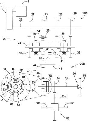
a transmission mechanism configured to output the power of the rotation support shaft to a traveling device, the transmission mechanism having a transmission flexibility portion allowing free rotation of the rotation support shaft by a set rotational angle,
wherein the transmission mechanism comprises:
a rotation transmission shaft operably coupled to the rotation support shaft via a gear coupling mechanism;
a front wheel output shaft coupled to the rotation transmission shaft for outputting power of the rotation transmission shaft to a front wheel as the traveling device; and
a rear wheel differential mechanism coupled to the rotation transmission shaft for outputting power of the rotation transmission shaft to a rear wheel as the traveling device; and
wherein the transmission flexibility portion is provided at a portion of the rotation transmission shaft to which portion the gear coupling mechanism is coupled,
wherein:
the transmission flexibility portion includes:
a transmitted rotation portion disposed at the rotation transmission shaft; and
a transmitting rotation portion configured to transmit power from the gear coupling mechanism to the transmitted rotation portion, and
the transmitted rotation portion includes a transmitting protrusion engaged in a recessed portion of the transmitting rotation portion so as to allow positional displacement between the recessed portion and the transmitting protrusion, and
wherein:
the transmission mechanism further comprises a transmission gear gear-coupled with the rotation support shaft, and
the transmitting rotation portion is disposed on the transmission gear.
|