CPC Definition - Subclass H01Q
This place covers:
an electrical conductor or array of conductors that radiates signal energy (transmitting) or collects signal energy (receiving); it's a transducer between a guided electromagnetic wave e.g. in a coaxial cable, waveguide, stripline and an electromagnetic wave in free space; the reciprocity relation is valid; the antenna is a passive linear reciprocal device That part of a transmitting or receiving system that is designed to radiate or to receive electromagnetic waves.
This place does not cover:
Radiators or antennas for microwave heating |
Examples of places where the subject matter of this place is covered when specially adapted, used for a particular purpose, or incorporated in a larger system:
Radio direction-finding; radio navigation; determining distance or velocity; locating | |
Beacons or beacon systems using radio waves | |
Direction-finders using radio waves | |
Circuits or components for simulating antennas, e.g. dummy antenna | |
Near-field transmission systems using the near field of leaky cables | |
Cells with adaptive channel assignment | |
Cell structures using beam steering | |
Communication route or path selection based on characteristics of available wireless antennas |
Attention is drawn to the following places, which may be of interest for search:
Microwave radiators for near-field therapeutic treatment | |
Apparatus for testing antennas or for measuring antenna characteristics | |
Radiation diagrams of antennas; antenna testing | |
using anechoic chamber | |
Modification of radiation pattern for cancelling noise or interfering signals | |
Means for calibrating or monitoring | |
Optical elements | |
Photonic crystals | |
Recognition and presentation of data; record carriers; handling record carriers | |
Transponder cards without electrical contacts | |
Waveguides | |
Line connectors; current collectors | |
Modulating electromagnetic waves in radiation field of antenna | |
Impedance networks | |
coupling circuits between transmission lines and antennas | |
impedance-matching networks | |
Hand-held transceivers | |
with reducing RF exposure | |
Radio transmission systems | |
Diversity systems | |
at transmitting station | |
at receiving station | |
Relay systems | |
Capacity expanding techniques | |
Monitoring, testing | |
Selecting | |
Printed circuits; Casings or constructional details of electric apparatus; manufacture | |
screening against electric or magnetic fields |
This place covers:
Structural details or features of antennas not dependent on electric operation and applicable to more than one type of antenna. However, structural details or features described with reference to an antenna of a particular type are classified in the group or sub-group appropriate to that type. This implies that any class under H01Q 1/00 should normally be accompanied by another class specifying the antenna type and/or working principle.
This place does not cover:
Arrangements for varying orientation of directional pattern |
This place covers:
Power handling capability means efficiency. Also effects due to high-power use, e.g. multipaction, (passive) intermodulation, as far as it relates to antennas, are to be classified here.
Illustrative example of subject-matter classified in this group:
Attention is drawn to the following places, which may be of interest for search:
Cooling |
This place covers:
Also covered by this group: reduction of mechanical deformations of an antenna, mast, etc.
Illustrative example of subject-matter classified in this group:
Attention is drawn to the following places, which may be of interest for search:
Damping of vibrations in general |
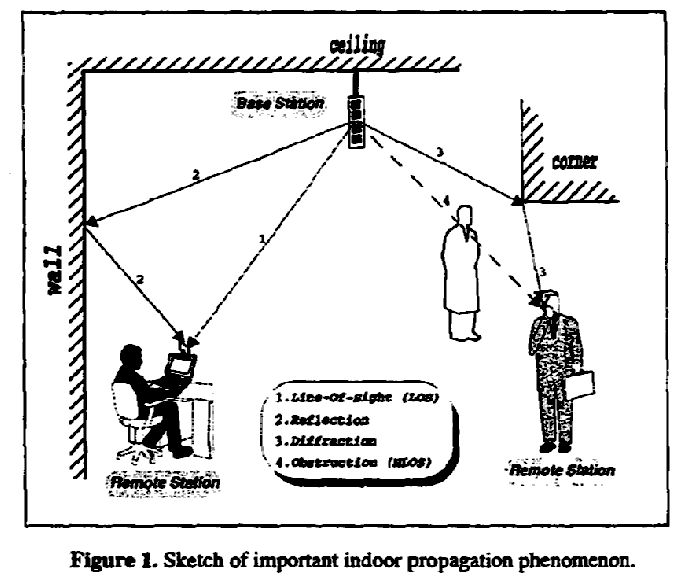
This place covers:
Indoor coverage with distributed antennas. 'Indoor' is to be interpreted in a broad sense, e.g. inside an airplane, room, building.
Illustrative example of subject-matter classified in this group:
This place covers:
Heating for removing snow or ice, for example used to blow droplets of water of the radome of a horn radiator in an earth station antenna. Cooling of T/R modules (see also H01Q 21/0025 Modular arrays).
Illustrative example of subject-matter classified in this group:
Attention is drawn to the following places, which may be of interest for search:
Radomes |
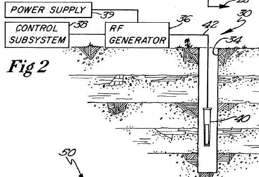
This place covers:
In a borehole, tunnel, underground or underwater.
Illustrative example of subject-matter classified in this group:
This place covers:
Originally used for lamps on masts; now also used for a LED on an antenna of a mobile phone. See the class F21S 8/00 as lighting devices for signalling; lamps on antennas or powerlines; antenna markers.
Illustrative example of subject-matter classified in this group:
This place covers:
For example:
Illustrative example of subject-matter classified in this group:
This place does not cover:
Collapsible loop antennas | |
Collapsible H-antennas or Yagi antennas |
Attention is drawn to the following places, which may be of interest for search:
Collapsible supports | |
Collapsible helical aerials | |
Collapsible reflecting surfaces |
Not used for the extractable antennas as used on mobile phones, nor for the clamshell phones with integrated antennas.
This place covers:
For example:
Illustrative example of subject-matter classified in this group:
This place covers:
For example:
Illustrative example of subject-matter classified in this group:
Attention is drawn to the following places, which may be of interest for search:
Balloon supported antennas |
This place covers:
Using (normally) a hinge.
Illustrative example of subject-matter classified in this group:
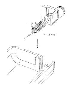
This place covers:
For example:
Traditional whip antenna with a mounting coil for a vehicle, rubber duck antenna (monopole coil wrapped in rubber cover).
Illustrative example of subject-matter classified in this group:
This place covers:
Tape measure used as an antenna with variable length; antennas used on a vehicle that can be (electrically) extended by means of a tape-measure like conductor, push-pull wire, etc.
Illustrative example of subject-matter classified in this group:
This place covers:
For example:
Illustrative example of subject-matter classified in this group:
Attention is drawn to the following places, which may be of interest for search:
Using clamps or clips | |
The stud, pin or spigot having two resilient parts on its opposite ends in order to connect two element |
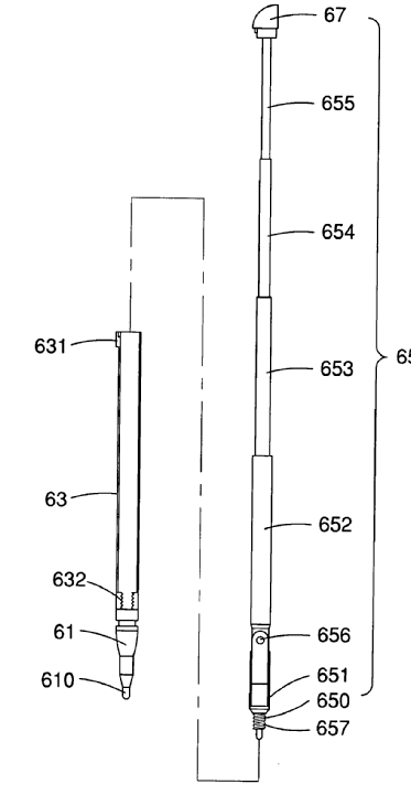
This place covers:
Thin hollow metallic tubes/pipes that can be pushed into one another; telescoping tubing (former active group for telescopic car or mobile antennas).
Illustrative example of subject-matter classified in this group:
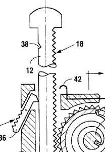
This place covers:
Extension/retraction by motor; BNC/bajonet type of releasable connecting arrangements.
Illustrative example of subject-matter classified in this group:
This place covers:
For example:
Illustrative example of subject-matter classified in this group:
This place covers:
Any support related to an antenna; lower groups have turned into mobile telecoms usage.
Illustrative example of subject-matter classified in this group:
Attention is drawn to the following places, which may be of interest for search:
For the purpose of scanning | |
Mounting structure for reflecting surfaces | |
Towers, masts, or poles | |
Supporting conductors in general |
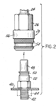
This place covers:
Details of coupling fastening devices by engagement/disengagement.
Illustrative example of subject-matter classified in this group:
Attention is drawn to the following places, which may be of interest for search:
Details of coupling devices operated by engagement or disengagement of coupling parts |
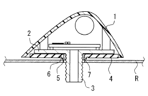
This place covers:
For example: through the vehicle body of automobiles. Mounting through the roof of another object, e.g. vehicle, house, housing.
Illustrative example of subject-matter classified in this group:
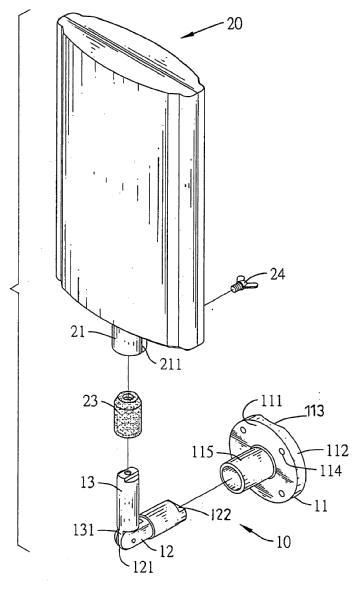
This place covers:
Wall mounted, also onto house roofs or tile roofs. If the wall is penetrated, it should be classified in H01Q 1/1214.
Illustrative example of subject-matter classified in this group:
This place covers:
Boom is to be interpreted as a supporting tubular pipe; cross-section of this pipe can be circular, rectangular, etc.
Illustrative example of subject-matter classified in this group:
Attention is drawn to the following places, which may be of interest for search:
Coupling of tubular pipes |
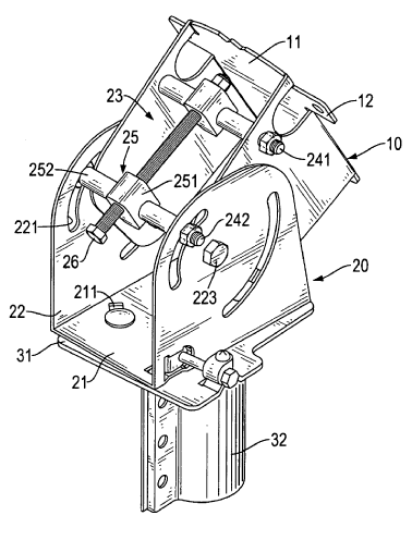
This place covers:
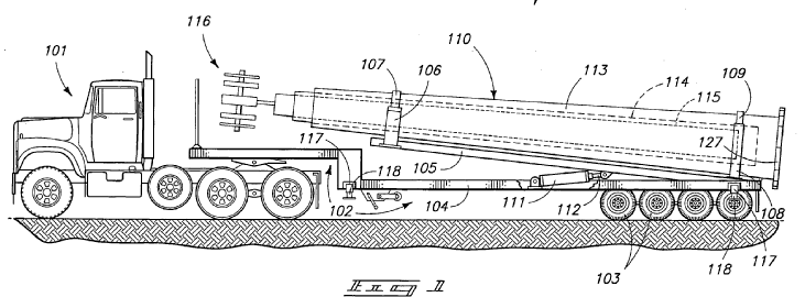
Tripods; vehicles for telescopic masts.
Illustrative example of subject-matter classified in this group:
Attention is drawn to the following places, which may be of interest for search:
Where the road or rail vehicle is only used as transportation means |
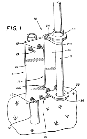
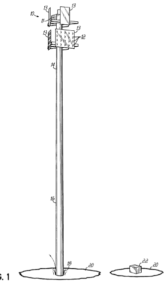
This place covers:
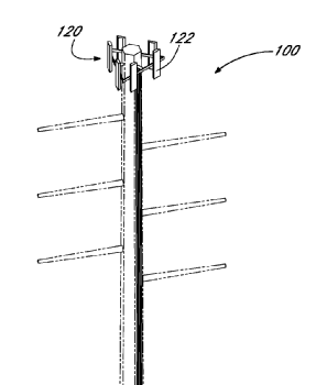
Tower, mast, pylon, pole, post: a self-supporting mast as lattice, or a concrete mast or guyed mast with guy cables for anchoring.
Illustrative example of subject-matter classified in this group:
Attention is drawn to the following places, which may be of interest for search:
Structures made of specified materials, of metal | |
Pre-stressed structures |
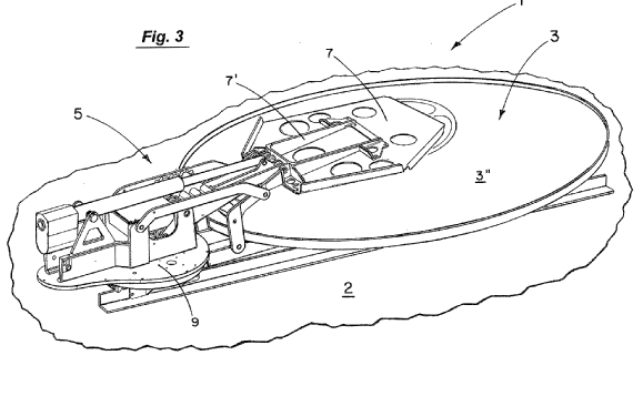
This place covers:
Antenna aiming; pointing the antenna to a fixed target by mechanical movement; sometimes also called tracking, i.e. means motion given to the major lobe of an antenna with the intention that a selected moving target, e.g. satellite, be contained within the major lobe. Collimation means adjusting accurately the line of sight, 'making parallel' However, scanning (a repetitive motion given to the major lobe of an antenna) in H01Q 3/10.
Illustrative example of subject-matter classified in this group:
Attention is drawn to the following places, which may be of interest for search:
Stabilising | |
Remotely controlled positioning |
This place covers:
The strength of the received signal is monitored, as used as a parameter for steering the positioning means; normally feed back processing is used.
Illustrative example of subject-matter classified in this group:
This place covers:
Not frequently used; large overlap with the classes H01Q 3/02 and groups thereunder.
Illustrative example of subject-matter classified in this group:
This place covers:
Glass antenna; window-; window pane-; on-vehicle glass antenna.
Illustrative example of subject-matter classified in this group:
US class: 343/713. It appears these kinds of applications are classified by the JPO under H01Q 1/32.
This place covers:
Illustrative example of subject-matter classified in this group:
Attention is drawn to the following places, which may be of interest for search:
Heating arrangements specially adapted for transparent or reflecting areas, e.g. for demisting or de-icing windows, mirrors or vehicle windshields |
This place covers:
Can be capacitive feeding through the complete glass layer, or partly through the glass layer, e.g. from within the layer to one outside thereof.
Illustrative example of subject-matter classified in this group:
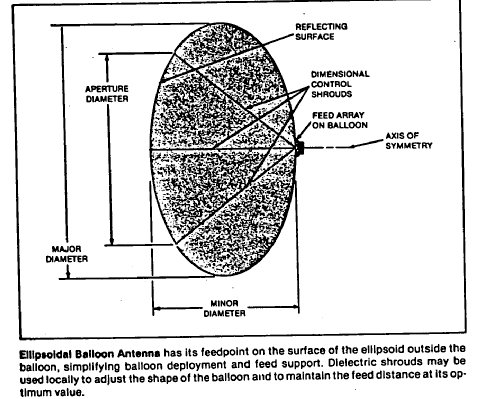
This place covers:
Not frequently used; overlap with H01Q 1/082: the distinction is that in this class the balloon is only the support, whereas in H01Q 1/082 the balloon is the antenna.
Illustrative example of subject-matter classified in this group:
This place covers:
Mechanical details for the so-called curtain antennas used in HF broadcast.
Illustrative examples of subject-matter classified in this group:
This place covers:
Illustrative example of subject-matter classified in this group:
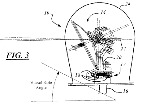
This place covers:
The unstable platform can be a ship, or a tower which is bending due to wind forces. Often a gimbal is used.
Illustrative example of subject-matter classified in this group:
Attention is drawn to the following places, which may be of interest for search:
Reducing wind-induced forces |
This place covers:
Any depointing due to the moving platform is corrected for using electronic means.
Illustrative example of subject-matter classified in this group:
Attention is drawn to the following places, which may be of interest for search:
Electronic scanning |
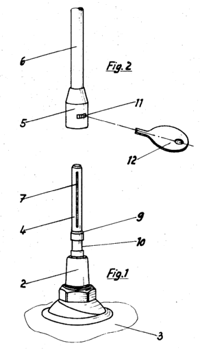
This place covers:
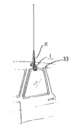
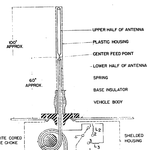
Mechanical details of fixtures; normally used in conjunction with a monopole-like radiator (stems from old car-antennas with a resilient base, e.g. coil).
Illustrative example of subject-matter classified in this group:
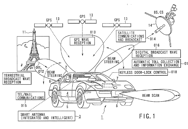
This place covers:
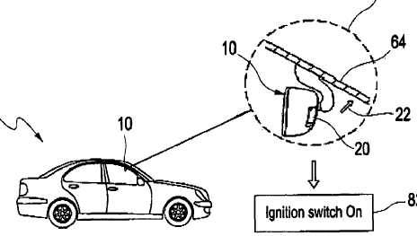
The antenna or antennas are mounted on something else; this something else is an item with a dedicated use: integration aspects of the antenna and the item.
Illustrative example of subject-matter classified in this group:
Attention is drawn to the following places, which may be of interest for search:
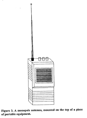
Portable transceivers |
This place covers:
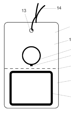
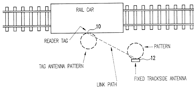
Antennas for a system of interrogator / reader which sends a unique identification (ID) to a tag which receives and sends back its stored information.
Illustrative example of subject-matter classified in this group:
This place does not cover:
Methods or arrangements for sensing record carriers, e.g. for reading patterns | |
Record carrier for use with machines and with al least a part designed to carry digital markings |
This place covers:
Antennas for interrogation reader (stationary, portable or hand-held) depending on operating frequency such as e.g. loop or dipole antennas; also multi-frequency, multiple antennas; antenna arrays.
This class is normally accompanied with a class relating to the antenna type, e.g. slot, dipole, coil, etc.
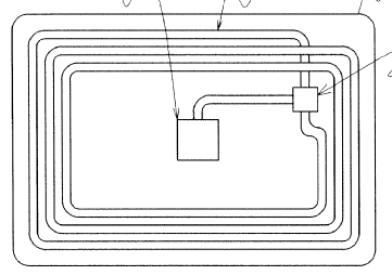
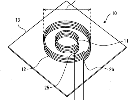
This place covers:
Antenna types depending on operating frequencies. Inductively coupled as multilayer coils, wrapped around ferrite cores, or radiatively coupled as dipoles, folded dipoles/monopoles, short loops, bow-tie, patch antennas
Illustrative example of subject-matter classified in this group:
This class is normally accompanied with a class relating to the antenna type, e.g. slot, dipole, coil, etc.
This place covers:
Illustrative example of subject-matter classified in this group:
Attention is drawn to the following places, which may be of interest for search:
Remote reading of utility meters | |
Transmission of measured values using a radio link in general |
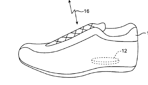
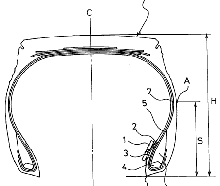
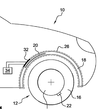
This place covers:
For monitoring pressure, wear, etc.
Illustrative example of subject-matter classified in this group:
Attention is drawn to the following places, which may be of interest for search:
Tyres in general |
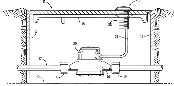
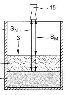
This place covers:
Normally a radar principle including time-of-flight is used to determine the distance between the radiating antenna the liquid or other material inside a container. This is to be used for details on the radiating antenna, not on other aspects for the measurement system (see G01F 23/284).
Illustrative example of subject-matter classified in this group:
Attention is drawn to the following places, which may be of interest for search:
Level measuring with electromagnetic waves in general |
This place covers:
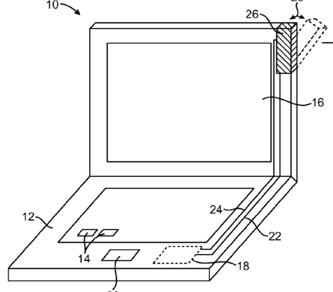
Antennas for computer equipment as laptops, notebooks, pdas, tablets, desktops or workstations.
Illustrative example of subject-matter classified in this group:
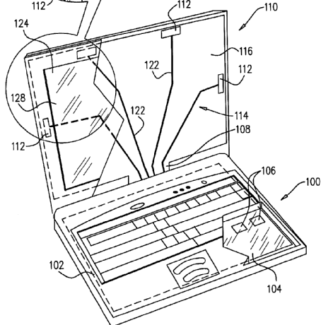
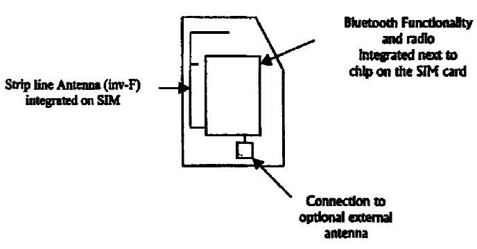
This place covers:
Also antennas mounted in(side) a hinge are considered here.
Illustrative example of subject-matter classified in this group:
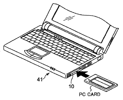
This place covers:
Typically the expansion card is removable; this reflects more the use of the antenna.
Illustrative example of subject-matter classified in this group:
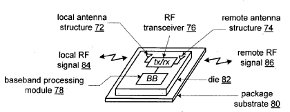
This place covers:
A small-size antenna which has an antenna element buried in a dielectric chip or stacked on the surface of a dielectric chip, (Murata appears to be the major applicant here).
Illustrative example of subject-matter classified in this group:
Attention is drawn to the following places, which may be of interest for search:
Chip carriers for flat cards H01L 23/49855.
This place covers:
Antennas for a wireless system of access points as base stations and of clients with laptops, notebooks, PDA's, desktops or workstations.
Illustrative example of subject-matter classified in this group:
This place does not cover:
Receiving set used in mobile communications | |
WLAN in general |
Attention is drawn to the following places, which may be of interest for search:
Specially adapted for indoor communication |
This place covers:
Documents where antennas are in a transmitting/receiving set, i.e. a transceiver. " "Receiving" here means actually receiving and/or transmitting.
Illustrative example of subject-matter classified in this group:
Attention is drawn to the following places, which may be of interest for search:
Portable transceivers | |
Hand-held transceivers | |
Portable telephone sets, e.g. cordless phones, mobile phones or bar type handsets |
This place covers:
GSM: Global System for Mobile Communication, also 3G and other telecommunications systems.
Illustrative example of subject-matter classified in this group:
This place does not cover:
With frequency mixer, e.g. for direct satellite reception or Doppler radar | |
Provided with an AC/DC converting device, e.g. rectennas |
This place covers:
Hand-held here excludes wireless phone for domestic use. In mobile (read: cellular) telephones.
Illustrative example of subject-matter classified in this group:
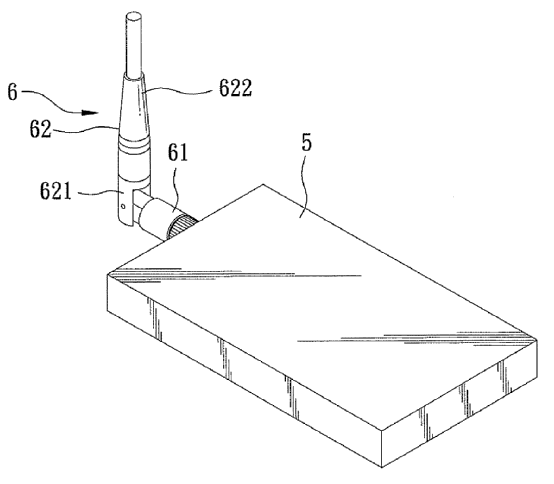
This place covers:
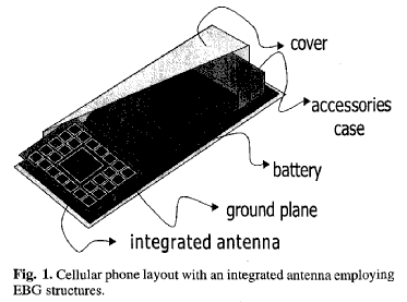
Stored/located/contained within the housing. Also when integrated within the shell of the phone housing.
Illustrative example of subject-matter classified in this group:
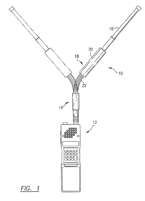
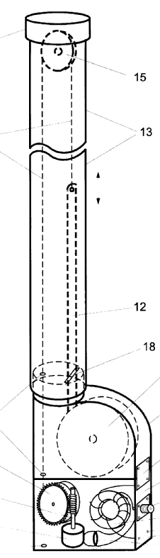
This place covers:
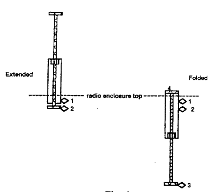
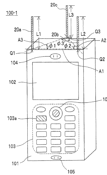
Normally antenna is within the housing, but part of it can be extracted (extendable; extractable; pulled out; stored, pushed in, contained; passive, retract+). The device should be claimed/disclosed; isolated antennas in H01Q 1/08 or H01Q 1/10 (and subgroups).
Illustrative example of subject-matter classified in this group:
Antennas per se are classified in H01Q 1/10 and subgroups.
This place covers:
Health protection, RF exposure. Overlap in H04B: "protect user against rf exposure". This class is about measures that influence the shape of the pattern, with the aim of reducing RF exposure / absorption by the user.
Illustrative example of subject-matter classified in this group:
Attention is drawn to the following places, which may be of interest for search:
Arrangements for reducing RF exposure to the user, e.g. by changing the shape of the transceiver while in use |
Power control after proximity detection (for example), should be in H04B.
This place covers:
To be interpreted as base stations in generalised cells (macro / micro / pico).
Illustrative example of subject-matter classified in this group:
In patent documents the following words are often used:
Cell station; hub station; cell site; cellular cell site; radio base station; homebase; central site, fixed site.
This place covers:
As LNB (Low noise block converter) or LNC (Low Noise Converter) or LNA (Low Noise Amplifier) as feeder of reflector antennas.
Illustrative example of subject-matter classified in this group:
Attention is drawn to the following places, which may be of interest for search:
Active antennas | |
Located in a hollow waveguide | |
Adaptations for transmission via a GHz frequency band, e.g. via satellite |
This place covers:
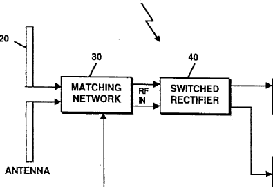
Rectifying antenna for microwave power transmission and conversion; antenna elements and rectifiers (diodes) are directly connected to produce a DC output; energy harvesting.
Illustrative example of subject-matter classified in this group:
Attention is drawn to the following places, which may be of interest for search:
Systems using reflection of radio waves, e.g. primary radar systems; Analogous systems |
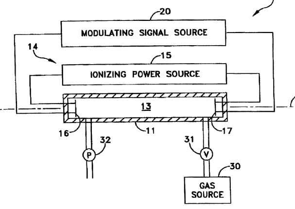
This place covers:
For example plasmas used for exciting waves; ionised gas columns excited by coil antenna at base.
Illustrative example of subject-matter classified in this group:
This place covers:
Illustrative example of subject-matter classified in this group:
This place does not cover:
Attention is drawn to the following places, which may be of interest for search:
Portable transceivers |
This place covers:
Mostly wristwatch-type-, clock-, timepiece antennas; collars; necklaces.
Illustrative example of subject-matter classified in this group:
Attention is drawn to the following places, which may be of interest for search:
Bracelets; Wrist-watch straps; Fastenings for bracelets or wrist-watch straps | |
Antennas attached to or as a component of clocks or watches | |
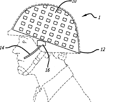
Transceivers carried on the body, e.g. in helmets |
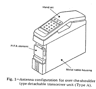
This place covers:
Military applications; use of these helmets by motor cycle drivers, soldiers.
Illustrative example of subject-matter classified in this group:
This place covers:
Illustrative example of subject-matter classified in this group:
(trains, cars are excluded)
This place covers:
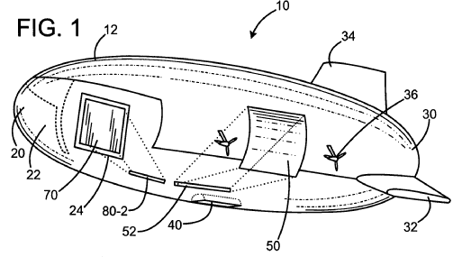
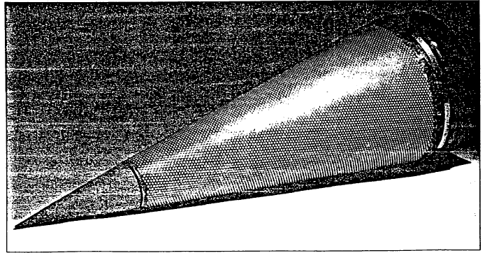
Antennas mounted in the nose of an airplane behind a radome.
Illustrative example of subject-matter classified in this group:
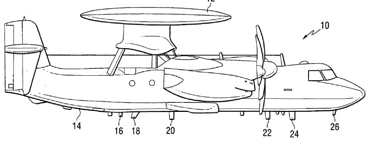
This place covers:
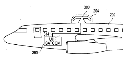
Antenna inside a radom projecting from the fuselage/housing of the vehicle.
Illustrative example of subject-matter classified in this group:
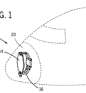
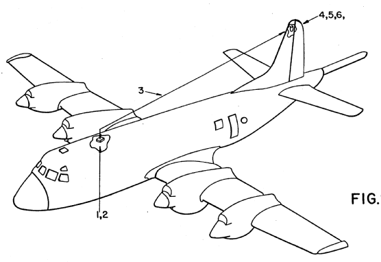
This place covers:
Form of a monopole antenna that is blade-shaped for strength and low aerodynamic drag. E.g. shape of a blade or fin protruding from the surface of the aircraft affecting the aircraft aerodynamics; e.g. monopole made by flat sheet.
Illustrative example of subject-matter classified in this group:
This place covers:
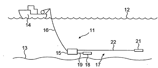
Wire antennas mounted on the vehicle; fuselage / housing used as support. Trailing antennas are NOT classified here.
Illustrative example of subject-matter classified in this group:
This place does not cover:
Means for trailing |
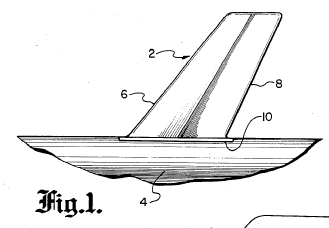
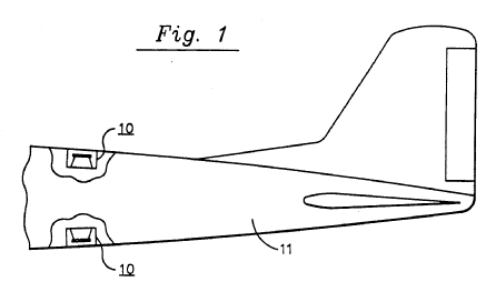
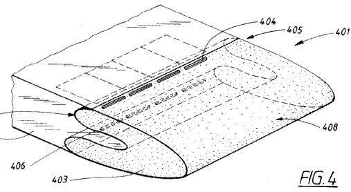
This place covers:
An antenna constructed into the surface of a mechanism, or of a vehicle, without affecting the shape of that surface. Contrast with a conformal antenna: An antenna (array) that conforms to a surface whose shape is determined by considerations other than electromagnetic; for example, aerodynamic or hydrodynamic.
Illustrative example of subject-matter classified in this group:
This place covers:
Only specifies the location where the antennas are flush mounted.
Illustrative example of subject-matter classified in this group:
This place covers:
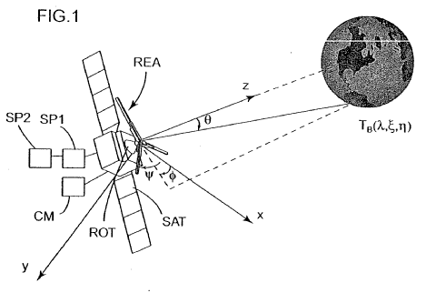
Antennas mounted in or on a satellite or space based station in aerospace, e.g. communication satellite as geostationary or low or medium earth orbiting (LEO or MEO).
Illustrative example of subject-matter classified in this group:
Attention is drawn to the following places, which may be of interest for search:
Cosmonautics; vehicles or equipment therefor | |
Space-based or airborne stations | H04B 7/185 and subgroups |
This place covers:
Antenna being trailed by aircraft, missiles, ships, satellites or balloons.
Illustrative example of subject-matter classified in this group:
This place covers:
Illustrative example of subject-matter classified in this group:
NOT the windscreen antennas.
This place covers:
Directed at the use of the antennas.
Illustrative example of subject-matter classified in this group:
In patent documents, the following abbreviations are often used:
LCD | Liquid Crystal Display |
This place covers:
Illustrative example of subject-matter classified in this group:
This place covers:
Illustrative example of subject-matter classified in this group:
Attention is drawn to the following places, which may be of interest for search:
Traffic control systems for road vehicles |
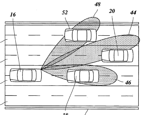
This place covers:
Safety and security aspects.
Illustrative example of subject-matter classified in this group:
Attention is drawn to the following places, which may be of interest for search:
Between land vehicles; between land vehicles and fixed obstacle |
This place covers:
Illustrative example of subject-matter classified in this group:
Attention is drawn to the following places, which may be of interest for search:
The record carrier being capable of non-contact communication |
This place covers:
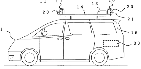
Directed at the location of the antenna on the vehicle.
Illustrative example of subject-matter classified in this group:
This place covers:
Illustrative example of subject-matter classified in this group:
This place covers:
Internal AND external mirrors.
Illustrative example of subject-matter classified in this group:
Attention is drawn to the following places, which may be of interest for search:
Rear-view mirror arrangements |
This place covers:
Illustrative example of subject-matter classified in this group:
This place covers:
Illustrative example of subject-matter classified in this group:
This place does not cover:
Mounted on windscreens |
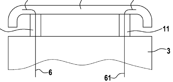
This place covers:
For example:
Roof rack; inside cavities within the vehicle.
Illustrative example of subject-matter classified in this group:
This place covers:
Illustrative example of subject-matter classified in this group:
This place does not cover:
For subaqueous use |
Attention is drawn to the following places, which may be of interest for search:
Retractable loop antennas |
This place covers:
Directed at specific shapes of the radiator.
Illustrative example of subject-matter classified in this group:
This place does not cover:
Attention is drawn to the following places, which may be of interest for search:
Device acting selectively as reflecting surface, as diffracting or as refracting device e.g. frequency filtering or angular spatial filtering devices |
This place covers:
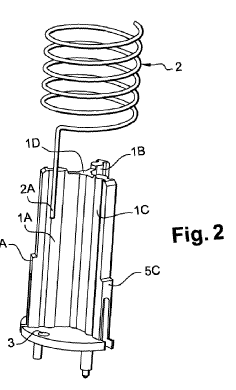
Definitions: An antenna whose configuration is that of a helix (the diameter, pitch, and number of turns in relation to the wavelength provide control of the polarization state and directivity) Here: helical antennas in the normal mode that means radiation broadside to the helix with linear polarization if helix diameter is less than lambda but length is comparable to lambda; i.e. helical monopole (coiling the antenna along its length).
H01Q 11/08+: helical antennas in axial/radial mode and circular polarization as monofilar, bifilar or quadrifilar (circumference in order of lambda and axial length several times larger than lambda).
Illustrative example of subject-matter classified in this group:
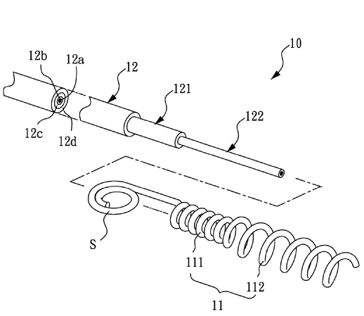
Attention is drawn to the following places, which may be of interest for search:
Helical aerials | H01Q 11/08 and subgroups |
This place covers:
Directed at specific/special materials.
This place covers:
Illustrative example of subject-matter classified in this group:
Attention is drawn to the following places, which may be of interest for search:
Using applied electromagnetic fields, e.g. high frequency or microwave energy |
This place covers:
Illustrative example of subject-matter classified in this group:
This place covers:
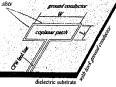
Sub-group of H01Q 1/36 whereby special structural forms of radiating elements are mounted on an insulating support.
Printed circuit antenna, an antenna of some desired shape bonded onto a dielectric substrate with various insulating materials, like dielectrics; ceramics, ferrites, ferroelectric composites.
Illustrative example of subject-matter classified in this group:
This place does not cover:
Patch antennas | |
Microstrip dipole antennas | |
Microstrip slot antennas | |
Transmission line microstrip antennas | |
Manufacturing reflecting surfaces using insulating material for supporting the reflecting surface |
Attention is drawn to the following places, which may be of interest for search:
Conductors in general |
In this place, the following terms or expressions are used with the meaning indicated:
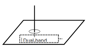
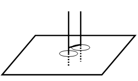
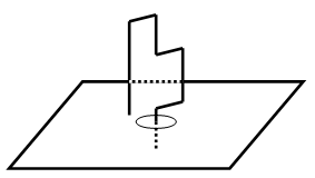
Chiral composites | embedding miniature helices in a non-chiral host medium; the names comes from the Greek "kheir" which means "hand" |
This place covers:
Protective cover like as radome and better matching to epsilon air.
Illustrative example of subject-matter classified in this group:
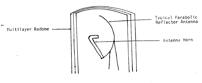
This place covers:
Elements are INSIDE radome.
Illustrative example of subject-matter classified in this group:
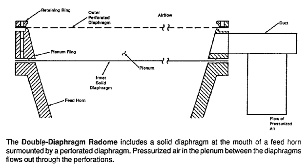
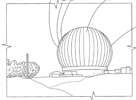
This place covers:
A cover, usually intended for protecting an antenna from the effects of its physical environment without degrading its electrical performance.
Illustrative example of subject-matter classified in this group:
In this place, the following terms or expressions are used with the meaning indicated:
Radome | Radar dome |
Irdome | !nftared dome |
This place covers:
Normally choice of material, thicknesses of layers, etc.
Illustrative example of subject-matter classified in this group:
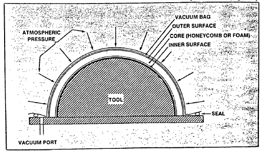
This place covers:
Normally multilayer or sandwich construction.
Illustrative example of subject-matter classified in this group:
This place does not cover:
Details of, or arrangements associated with, aerials, housings not intimately mechanically associated with radiating elements, e.g. radome, comprising a metallic grid |
This place covers:
Normally used using a moulding/molding process and expansion, e.g. polystyrene shells used for protection against weather influences.
Illustrative example of subject-matter classified in this group:
This place covers:
Metallic grid e.g. for heating; as polarizer or frequency selective surface (FSS).
Illustrative example of subject-matter classified in this group:
Attention is drawn to the following places, which may be of interest for search:
Devices acting selectively as reflecting surface, as diffracting or as refracting device, e.g. frequency filtering or angular spatial filtering devices |
This place covers:
Illustrative example of subject-matter classified in this group:
This place covers:
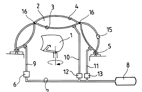
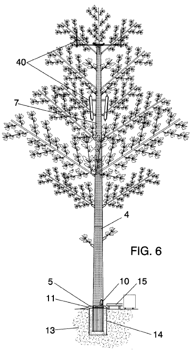
Artificial trees; disguising antenna in other objects; camouflage; nicer, (a)esthetic appearance for reflectors; patterning / coloring of antennas; devices with integrated perfume dispensers.
Illustrative example of subject-matter classified in this group:
This place covers:
For example:
Power distribution lines used for a lf radar application.
Illustrative example of subject-matter classified in this group:
Attention is drawn to the following places, which may be of interest for search:
Circuits for signal transmission via power distribution lines |
This place covers:
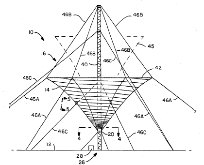
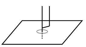
Counterpoise: A system of conductors, elevated above and insulated from the ground, forming a lower system of conductors of an antenna.
Illustrative example of subject-matter classified in this group:
Attention is drawn to the following places, which may be of interest for search:
Earthing pins |
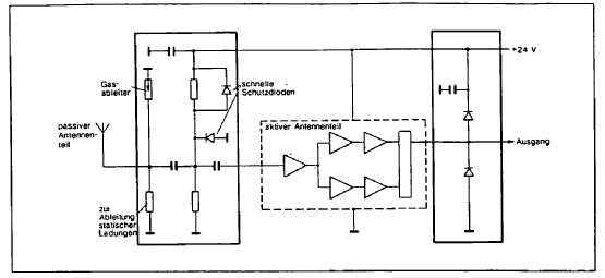
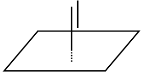
This place covers:
Only when integrated with antenna. The devices as such are in H01T.
Illustrative example of subject-matter classified in this group:
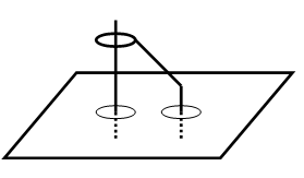
This place covers:
Increasing isolation between antennas.
Reducing the irradiation of objects.
Illustrative example of subject-matter classified in this group:
This place does not cover:
Absorbing means |
This place covers:
Antennas are next to each other, but have no relation to another: antennas on the same GSM mast, but dedicated to the same service.
Illustrative example of subject-matter classified in this group:
This place covers:
Antennas next to each other, and belong to the same array, i.e. Sharing a feeding system.
Illustrative example of subject-matter classified in this group:
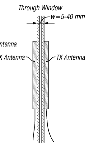
This place covers:
Solutions for overload / saturation at RX antenna: one antenna transmits, and at the same time, the other neighbouring antenna receives.
Illustrative example of subject-matter classified in this group:
Attention is drawn to the following places, which may be of interest for search:
Feed-through nulling for radar |
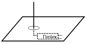
This place covers:
For example:
Grounded wall between a radiator and something else; fences.
Illustrative example of subject-matter classified in this group:
Attention is drawn to the following places, which may be of interest for search:
Anechoic chambers | |
Shielding of instruments | |
Shielding of CRT | |
Shielding of electrical apparatus or components |
This place covers:
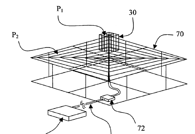
Reduing the influence of currents induced by the antenna onto, e.g. A support; increasing the decoupling of a ground-plane supported antenna, where the ground plane is not a counterpoise. ideally influence should be nothing, e.g. antenna on space craft.
Illustrative example of subject-matter classified in this group:
This place does not cover:
In a parabolic reflector antenna |
This place covers:
Changing or varying the orientation that is beam steering as changing the direction of the major lobe.
Related is beam scanning that is a repetitive motion given to the major lobe.
Changing or varying the shape that is beam forming.
Motion of the major lobe to have moving target within the lobe that is beam tracking.
Realized either:
- by mechanically moving the antenna or the feed or
- by electronically altering the aperture excitation with amplitude and phase.
This place does not cover:
Means for positioning |
This place covers:
Remote control aspects as such.
Illustrative example of subject-matter classified in this group:
Attention is drawn to the following places, which may be of interest for search:
Remote control in general |
This place covers:
The variations are mechanical variations, e.g. Deformable sub-reflectors in dual reflector antenna systems.
Illustrative example of subject-matter classified in this group:
This place covers:
The whole antenna moves, i.e. one needs.
Rotary joints, couplers between fixed TIR and rotating antenna. Rotary joints belong to H01P.
Illustrative example of subject-matter classified in this group:
This place covers:
Either azimuth, elevation or another axis of rotation, e.g. Polar axis for leo orbit satellites.
Illustrative example of subject-matter classified in this group:
This place covers:
Illustrative example of subject-matter classified in this group:
This place covers:
Normally variation of two (orthogonal) angles, e.g. Azimuth and elevation, polar and cross-polar angles.
Illustrative example of subject-matter classified in this group:
This place covers:
The direction of maximum radiation generates a cone whose vertex angle is in the order of the antenna half-power beamwidth.
Illustrative example of subject-matter classified in this group:
This place covers:
The movement is relative, one element moves w.r.t. another one, e.g. feed w.r.t. lens, sub-reflector w.r.t. feed. See also lower classes for specific cases of relative movement.
Illustrative example of subject-matter classified in this group:
Attention is drawn to the following places, which may be of interest for search:
Positioning |
This place covers:
Refracting device, like lens.
Diffracting device, like grating.
Illustrative example of subject-matter classified in this group:
This place covers:
Primary active element, like feed, radiating element.
Reflecting device, like sub reflector or main reflector.
Illustrative example of subject-matter classified in this group:
This place covers:
Mechanically moving the feed of the antenna, that is steerable-beam antenna.
Feed-motion, off-axis fed, that is lateral displacement of the feed.
Illustrative example of subject-matter classified in this group:
This place covers:
Reflector tilt; subreflector scanning.
Illustrative example of subject-matter classified in this group:
This place covers:
Type of electronic scanning, i.e. scanning an antenna beam by electronic or electric means without moving parts, inertialess scanning.
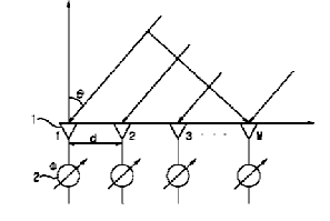
Frequency scanning is defined as that the direction of the radiated beam is controlled by changing the operating frequency. It is based on the fact that the phase delay through a length of transmission line changes with frequency; no phase shifters.
Frequency hopping means that the frequency of the transmitter abruptly changes (or hops) in accordance with a pseudo-random code sequence; the receiver tracks these changes.
With a phased array without phase shifters, frequency hopping will inevitably result in beam scanning.
Illustrative example of subject-matter classified in this group:
This place covers:
Scanning of a radiating beam by selecting a particular fixed beam from an available set of fixed beams.
Due to the switching, there exists only a single beam at a time. The non-selected elements are simply not used. This concept is distinctively different from having a multiple beam array antenna with a beam former for which only a specific beam port is selected. In this specific case all the active elements will radiate/receive at all times.
For example, if the direction of main radiation of two antenna elements is different, selecting one or the other element will change the direction of the beam.
Illustrative example of subject-matter classified in this group:
Attention is drawn to the following places, which may be of interest for search:
At receiving station, e.g. space diversity | H04B 7/08 and subgroups for diversity systems |
This place covers:
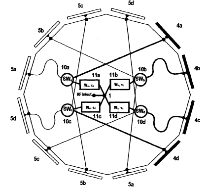
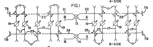
Circumferential scanning means that the beams scan around the circumference e.g. with a cylindrical array, an array on a cylinder with transfer switches (double-pole, double or four throw switches).
Illustrative example of subject-matter classified in this group:
This place covers:
The switching in fact causes the phase center of the active element to change, e.g. lateral displacement. As a consequence, also the produced beam changes direction.
Illustrative example of subject-matter classified in this group:
This place covers:
On-off switching of elements or parts of a single element.
Illustrative example of subject-matter classified in this group:
This place covers:
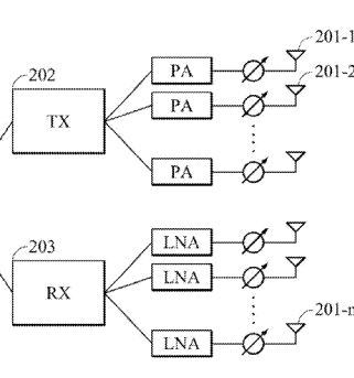
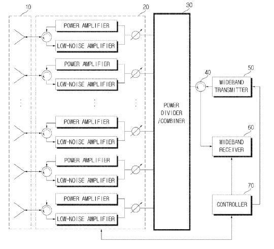
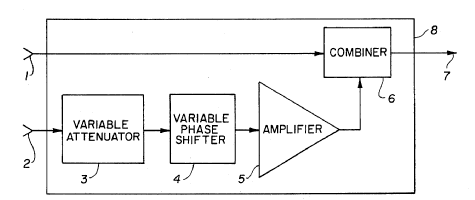
Varying the phase or amplitude:
- beam can be scanned by using phase shifters to change the excitation phases of its array elements;
- and forming a desired radiation pattern by amplitude control via amplifiers/attenuators.
Varying the distribution of energy across aperture:
- amplitude distribution (uniform or non-uniform) over a aperture, near or on an antenna, on which it is convenient to make assumptions over the field values at external points e.g. applying amplitude taper for reducing sidelobes as Taylor or Dolph-Chebyshew distributions.
Illustrative example of subject-matter classified in this group:
This place does not cover:
Arrangements for changing or varying the orientation or the shape of the directional pattern of the waves radiated from an antenna or antenna system using mechanical relative movement between primary active elements and secondary devices of antennas or antenna systems | |
Arrangements for varying the orientation in accordance with variation of frequency of radiated wave | |
Arrangements for varying the orientation by switching energy from one active radiating element to another, e.g. for beam switching |
Attention is drawn to the following places, which may be of interest for search:
Network planning using cell structures using beam steering |
In this place, the following terms or expressions are used with the meaning indicated:
Beam forming | weighting and summing the elements signals |
Weighting | phase and amplitude applied to the signals; changing the weighting of one element to the other changes the pattern in direction and beamwidth/ beamform |
Analog beamforming (RF beamforming) | phase and/or amplitude control takes place in the RF domain |
Digital beamforming | phase and/or amplitude control takes place inside a beamforming computer / processor, after having sampled the RF signals using an A/D convertor.In a digital beamforming array, the received signals are detected and digitized at the element level; the digitized signals are then processed in a digital computer to form a desired beam on transmit and/or receive; processing of the digitized signals in time and amplitude according to a software program. |
In patent documents, the following abbreviations are often used:
ESA | electronically scanned array |
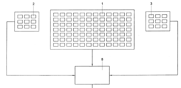
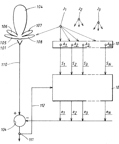
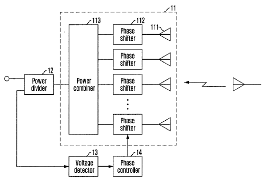
This place covers:
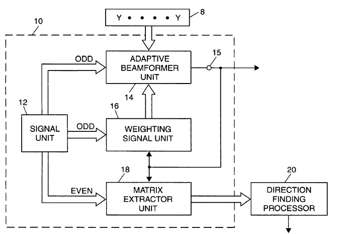
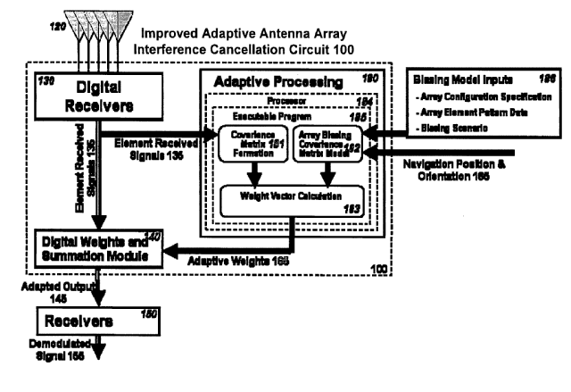
Adaptivity: automatic signal-dependent weight adjustment to reduce unwanted signals and/or emphasize the desired signal or an antenna system having circuit elements associated with its radiating elements such that one or more of the antenna properties are controlled by the received signal.
Different Weight-determining Algorithms in the Adaptive Control Processor.
Applebaum-Howell circuit.
Illustrative example of subject-matter classified in this group:
Attention is drawn to the following places, which may be of interest for search:
In this place, the following terms or expressions are used with the meaning indicated:
LMS | Least-Mean-Square algorithm |
MUSIC | Multiple Signal Classification |
ESPRIT | Estimation of Signal Parameters via Rotational Invariance Techniques |
DOA | Direction of Arrival |
This place covers:
Illustrative example of subject-matter classified in this group:
In this place, the following terms or expressions are used with the meaning indicated:
Null steering | to control, usually electronically, the direction at which a directional null appears in the radiation pattern or directing the peak of the directivity to the direction of arrival or the location of a signal source and by directing a null point of the directivity to the direction of an incoming disturbance wave |
This place covers:
Illustrative example of subject-matter classified in this group:
This place covers:
Illustrative example of subject-matter classified in this group:
This place covers:
Sidelobe canceller, sidelobe blanker: destructive interference is used for blanking a null in a pattern by subtraction of signals having identical amplitude and phase: this causes a distinct null in the pattern.
Illustrative example of subject-matter classified in this group:
This place covers:
Illustrative example of subject-matter classified in this group:
This place covers:
Adjusting terminating reactances, e.g. Varicap diodes.
Illustrative example of subject-matter classified in this group:
This place covers:
Perform beam steering in an automatic fashion by retransmitting an incoming selfphased signal in a phase conjugated manner. The received signal is then retransmitted in the direction it was originated from. Active devices can be added to enhance the return signal (that is, active retrodirective antenna system); as retro-reflector or retro-reflective transponder; Van Atta array.
Attention is drawn to the following places, which may be of interest for search:
Wherein continuous-type signals are transmitted |
This place covers:
A receiving antenna system that introduces a phase distribution among the array elements so as to maximize the received signal, regardless of the direction of incidence; Contrast with: Retrodirective.
This place covers:
Phased array in/at the focal point of a lens or parabolic/hyperbolic dish.
Illustrative example of subject-matter classified in this group:
This place covers:
This gives the possibility of shaping the beam that is incident upon the focussing device, as well as its angle of incidence.
Examples:
- rotating obstacles in front of a conical horn;
- aperture shaping: the aperture of a feed horn or of a focused reflector surface is modified.
Illustrative example of subject-matter classified in this group:
This place does not cover:
Switching | |
Phased-array feeds |
This place covers:
Testing means diagnosis of faults by integral monitors; with built-in performance monitoring and measurement of aperture distribution; near-field measurements with a probe antenna; built-in test equipment BITE.
Calibration means to standardize by determining the deviation from standard so as to ascertain the proper correction factors, i.e. diagnosis of errors in terms of amplitude and/or phase.
Illustrative example of subject-matter classified in this group:
Attention is drawn to the following places, which may be of interest for search:
Anything dealing with the calibration of phased arrays is classified here, e.g. single carrier, multi-carrier systems, measuring radiation diagrams of aerials |
This place covers:
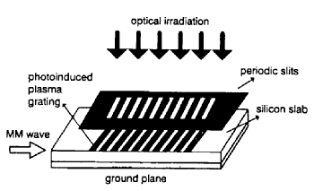
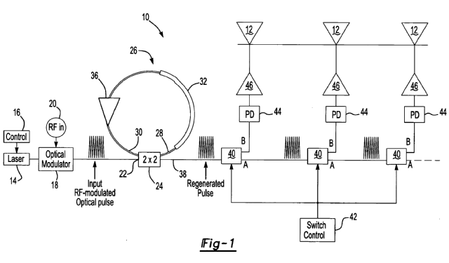
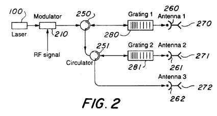
Optical control means beam scanning by the use of photoelectric conversion i.e. optical to microwave conversion and reverse with lasers, photodiodes and fibers as true time delay elements; photonic time shifter; electric-optical conversion elements.
Illustrative example of subject-matter classified in this group:
Attention is drawn to the following places, which may be of interest for search:
Optical fibre networks |
This place covers:
Other method beside beam steering/scanning with phase shifters using delay lines which introduce a frequency independent time delay; e.g. switchable delay lines; Blass matrix.
Illustrative example of subject-matter classified in this group:
This place covers:
An input electrical signal is launched as acoustic signal by an input transducer. The acoustic signal undergoes a finite delay as it propagates over the medium and then reconverted to electrical signal. Surface Acoustic Wave (SAW) or Magnetostatic Wave (MSW) with YIG material as ferrimagnetic material.
Illustrative example of subject-matter classified in this group:
This place covers:
For example: time delays in sub-array, phase shifters in each element.
The time delay becomes important in wideband applications where 2*pi phase shift do not suffice.
See also: R.C. Hansen, Phased array antennas, section 6.2.
Illustrative example of subject-matter classified in this group:
This place does not cover:
Using acoustic or magnetostatic wave devices |
This place covers:
Varying the amplitude for shaping the antenna pattern as beamwidth and sidelobes; shaped beams, varying the amplitude distribution of the radiating aperture e.g. by amplitude taper:
- with power dividers, e.g. as directional coupler; hybrid ring; magic T, branch-line coupler;
- with attenuators,
- with amplifiers.
Illustrative example of subject-matter classified in this group:
This place covers:
Varying the distribution of the phase over any path, surface or radiation pattern for steering, scanning the beam.
Phase shifters can be broadly classified as mechanical or electronic, depending on whether the phase control is achieved through mechanical or electronic tuning.
Illustrative example of subject-matter classified in this group:
This place does not cover:
Array of radiating elements provided with a feedback control over the element weights, adaptive arrays | |
Phased-array fed focussing structure | |
Time delay steered arrays | |
Varying the electric or magnetic characteristics of reflecting, refracting, or diffracting devices associated with the radiating element |
This place covers:
Mechanical phase shifters are generally constructed in coaxial line or metallic waveguides. The insertion phase is varied by means of mechanical tuning, such as variation in the physical length or rotation-displacement of a dielectric slab inside the waveguide.
Illustrative example of subject-matter classified in this group:
This place covers:
Electronic phase shifters as:
- ferrite phase shifter and
- semiconductor device phase shifter that use semiconductor junction devices as electronic control element.
Illustrative example of subject-matter classified in this group:
This place does not cover:
Active lenses or reflecting arrays |
This place covers:
With continuous variation (analog phase shifter).
In discrete step (digital): too coarse resolution will lead to discretisation lobes.
Ferrite phase shifters:
- enclosed in waveguide;
- using a microstrip configuration; ferrimagnetic material; Faraday rotator phase shifter; either non reciprocal or reciprocal.
Semiconductor device phase shifters:
- with PIN-diodes;
- Varactor diodes, Schottky diodes;
- FET switches.
Illustrative example of subject-matter classified in this group:
Attention is drawn to the following places, which may be of interest for search:
Combined with time delay devices | |
Phase shifter as such should be dealt with in |
This place covers:
Digital means in steps; e.g. as 3 bit phase shifter(180°,90°,45°):
- with hybrid;
- with circulator;
- with loaded line;
- with switched line.
Illustrative example of subject-matter classified in this group:
This place covers:
Illustrative example of subject-matter classified in this group:
This place covers:
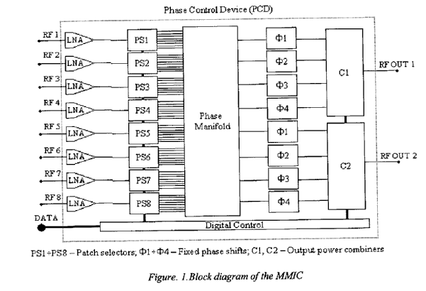
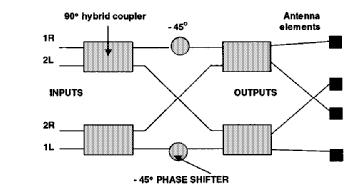
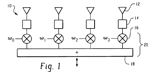
Circuit configuration whereby signal inputs are connected with antenna elements via a matrix with phase shifters and hybrid couplers; Beam Forming Matrix / Network (BFM,BFN). The inputs of the matrix are referred to beam ports, since the signal of this port corresponds to a beam direction. The BFN therefore works as a kind of Fourier transformer.
For example:
Butler -Matrix: Network with number of inputs and outputs; multibeam; beam scanning by sequentially feeding the elements with the phase increment provided by the matrix. The phase gradient over the outputs is dependent on the beam port chosen.
Blass-Matrix: a number of travelling wave feed lines are connected to a linear array; at each crossover point a small will be coupled and the path difference between the input and each element control the beam direction.
Illustrative example of subject-matter classified in this group:
This place covers:
Beam forming is carried out on Intermediate Frequency (l.F.). l.F. is formed when the R.F. signal coming from the antenna elements is mixed with local oscillator to convert the R.F. down to a more convenient frequency, where, for example, accurate phase shifts are easier to be performed.
Illustrative example of subject-matter classified in this group:
This place does not cover:
Optically controlled phased array |
This place covers:
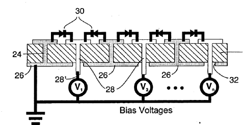
- With ferroelectric materials: have the property of variable dielectric constant with applied DC bias voltage; ferroelectric scanning.
- With ferrite using magnetic phase control by changes the effective permeability by magnetic bias.
Illustrative example of subject-matter classified in this group:
This place covers:
Typically material parameters are varied to achieve the desired effect. The antenna is a leaky antenna.
Illustrative example of subject-matter classified in this group:
This place does not cover:
Frequency scanning | |
Non-resonant leaky-waveguide or transmission-line aerials |
This place covers:
For example: one active element and a number of passive elements, reactively loaded and adjustable. Irrespective of the antenna types: here only the principle is classified.
Illustrative example of subject-matter classified in this group:
Attention is drawn to the following places, which may be of interest for search:
The primary active element being end-fed and elongated |
This place covers:
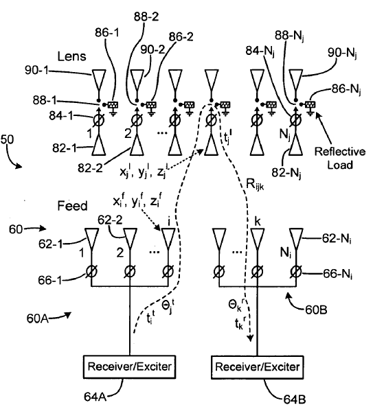
Reflective array: An antenna consisting of a feed and an array of reflecting elements arranged on a surface and adjusted so that the reflected waves from the individual elements combine to produce a prescribed secondary pattern. The reflecting elements can be waveguides containing electrical phase shifters and terminated by short circuits.
Active lens: array of active units (receive-amplify-transmit), that is transponders, in which also phase shifts can be introduced. The array behaves as a lens, and high power can be generated.
Active lens is therefore of the transmission type, whereas a reflecting array is of the reflection type.
Illustrative examples of subject-matter classified in this group:
This place covers:
An antenna designed to operate simultaneously, without modification, in any of a number of pre-set frequency bands.
Remark: It is sometimes difficult to draw a clear line between some of the groups, but here are some clear examples representing the underlying ideas.
Dual-band imp-match: H01Q 5/335
Two feed points: H01Q 5/35
Different paths: H01Q 5/364
Branching: H01Q 5/371
Parasitic: H01Q 5/378
Imbricated, interleaved: H01Q 5/40
Special feed arrangement: H01Q 5/50
Common feeder: H01Q 21/30
This place does not cover:
Combinations of separate active antenna units operating in different wavebands and connected to a common feeder system |
Attention is drawn to the following places, which may be of interest for search:
Ground plane features per se | |
The changing per se of electrical (for example by switching) or physical length of the antenna | |
Receivers or transmitters adapted for more than one waveband |
Antennas with (inherent) broadband characteristics are classified in the antenna type, e.g. folded or loaded or extended surface monopole antennas with broadband are classified in the relevant antenna type groups.
This place covers:
Multiband aspects for resonant antennas (lambda/4 or lambda/2) as e.g. vertical monopole or horizontal dipole antennas.
Single resonant multiband dipole- or monopole antennas.
Resonant antennas with trap circuits or stub elements.
Illustrative example of subject-matter classified in this group:
This place covers:
Collinear means a linear arrangement of radiating elements with their axis lying in a straight line (vertical or horizontal), e.g. multi-band trap centre-fed dipole.
Illustrative example of subject-matter classified in this group:
This place covers:
Antennas with specific applications related to two or more different wavebands, where focus is on the application and not on how the achievement of the different wavebands is done.
This place covers:
Arrangements of antennas with operation on both RF and non-RF wavebands.
Attention is drawn to the following places, which may be of interest for search:
IR, Optics | |
Integrated light sensitive semiconductor devices |
Attention is drawn to the following places, which may be of interest for search:
Non-sinusoidal waves. |
This place covers:
Antenna arrangement operating on two or more wavebands, where certain properties are achieved over these bands, such as constant polarisation, beam width, etc.
This place covers:
Antennas with special features making the antenna operable over two or more different frequency bands.
Antennas considered have a single fed radiating elements, connected radiating elements, or a combination of a fed radiating element and a non-directly fed element (parasitic element).
Attention is drawn to the following places, which may be of interest for search:
Imbricated or interleaved structures |
This place covers:
Antennas having frequency dependent circuits in order to create multiple resonances, for example by trap circuits blocking parts of the antenna at certain frequencies.
This place covers:
Frequency dependent circuits at the (single) feed, and which are responsible for the multiple wavebands.
The circuit typically has one input and one output.
This place does not cover:
Different modes due to frequency dependent circuits |
This place covers:
Illustrative example of subject-matter classified in this group:
This place covers:
Antennas having different current paths, for example:
This place covers:
Antennas, where the different current paths are also branching, for example:
This place covers:
The arrangement of a fed antenna with a parasitic element in order to create different wavebands.
Attention is drawn to the following places, which may be of interest for search:
Parasitic elements for shaping the beam |
This place covers:
Antenna arrangement of fed radiating elements, where there is a structural and/or electromagnetic relationship between the elements.
Antenna arrangement where two different types of antennas (dipole and monopole, slot and patch, etc.) are partly overlapping.
Illustrative examples of subject-matter classified in this group:
Attention is drawn to the following places, which may be of interest for search:
Separate independent antennas. | |
Antennas with common feed. |
This place covers:
- reflecting device, e.g. parabolic reflector;
- diffracting device e.g. grids;
- refracting device e.g. lens.
This place covers:
For example double coaxial horn; horn in horn; nested horn. Typically, the feeds have the same phase centre.
This place covers:
For example vertical or horizontal stacked Yagi-Uda antennas
This place covers:
Antennas having special feeding/matching arrangements at or before the feeding for directing the signal from the antenna on at least two paths, for example diplexer circuitry.
Illustrative example of subject-matter classified in this group:
This place covers:
An antenna whose configuration is that of a loop, bent into the shape of closed curve.
Two types:
- Small loops
Circumference of the loop is small compared to lambda with constant current distribution (same value at any point) - magnetic antenna (more H-field) - max. sensitivity in the plane; nulls are perpendicular to the plane of the loop - circular (ring) with a number of windings as a solenoidal coil on a frame: multiturn loop; Alford loop antenna (see H01Q 7/08).
- Large loops (resonant loops)
The loop circumference is comparable to lambda with sinusoidal current distribution (half- or one wavelength loop); -more E-field (resonant loops; dual to dipole antenna) - max. sensitivity perpendicular to the plane - circular (ring); square (Quad, that is four sides lambdal4); delta, diamond shapes.
This place covers:
Illustrative example of subject-matter classified in this group:
Attention is drawn to the following places, which may be of interest for search:
Tuning resonant circuits |
This place covers:
There are mechanical measures foreseen to collapse the aerial.
Illustrative example of subject-matter classified in this group:
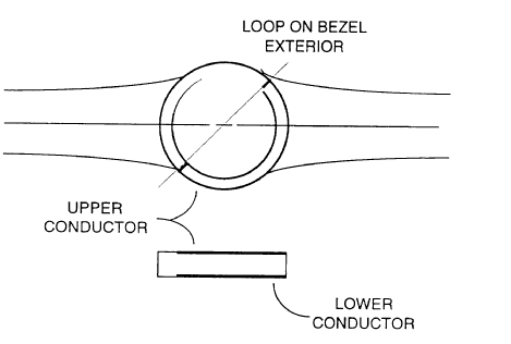
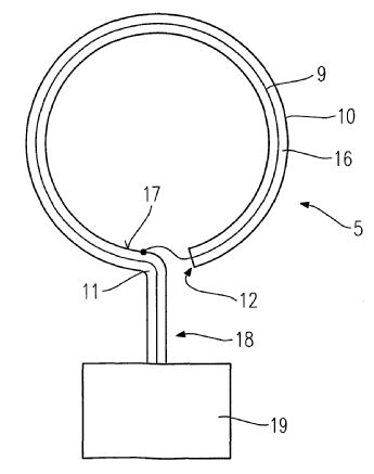
This place covers:
For improving the directivity the loop antenna is drawn into a metal tube with a gap. The gap constitutes a potential source which generates a current at the exterior side of the tube. The current generates a magnetic field around the external side of the tube (screened by the metal tubes).
Illustrative example of subject-matter classified in this group:
Application for article surveillance (G08B 13/2402, G08B 13/2402).
This place does not cover:
In patent documents, the following words/expressions are often used as synonyms:
- shielding, electrostatic shielding
This place covers:
The voltage at the terminals of a small loop antenna can be increased by filling the loop with a core of permeable material. The effect of the core is to increase the magnetic flux through the area of the loop.
Choice of materials with different permeability.
Illustrative example of subject-matter classified in this group:
This place does not cover:
Collapsible aerials; Retractable aerials |
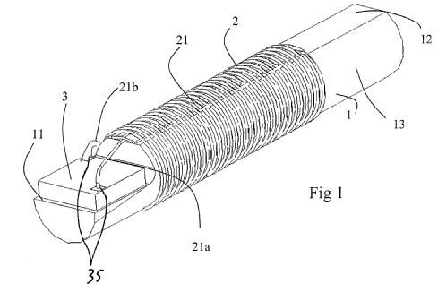
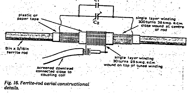
This place covers:
A loop receiving antenna with a ferrite rod core used for increasing its radiation efficiency.
Illustrative example of subject-matter classified in this group:
In this place, the following terms or expressions are used with the meaning indicated:
Ferrite | high permeability and high resistance; are high permeable isolators; e.g. mangan- or nickel ferrite |
This place covers:
An integral number of lambda/2 -standing waves of current or voltage; self-resonant e.g. lambda/2-dipole; lambda/4 monopole; lambda/2 X lambda/2 -square patch. Also electrically small antennas whose dimensions are such that it can be contained within a sphere whose diameter is small compared to a wavelength at the frequency of operation.
Attention is drawn to the following places, which may be of interest for search:
Loop antennas | |
Waveguide horns or mouths; Slot antennas | |
Combinations of active elements with secondary devices to give desired directional characteristic | |
Combinations of two or more active elements |
This place covers:
Originally intended for pulsed operation; now slowly moving to UWB type of operation.
Illustrative example of subject-matter classified in this group:
This place covers:
Used for pulsed signals; transient signals; reduction of ringing effect after extremely short pulses.
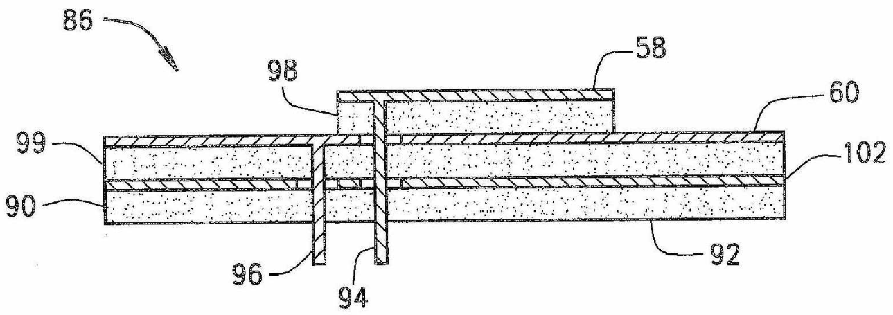
Illustrative example of subject-matter classified in this group:
This place covers:
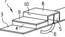
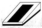
Microstrip device with two parallel conducting layers, a ground plane and and a resonant plate, separated by a thin dielectric substrate and a feeder coupled to the resonant plate.
Rectangular patch; cavity- backed patch; inverted patch i.e. dielectric on top.
Illustrative example of subject-matter classified in this group:
See: XP000965987, XP001175135, XP00680870, XP00026.
H01Q 9/065 Microstrip dipole antennas (a resonator made of a narrow conductor strip ecxited in the middle).
H01P microstrip transmission lines.
JPO classifies in H01Q 13/08 ("Radiating ends of two-conductor microwave transmission lines e.g. of coaxial lines, of microstrip lines") resp. in H01Q 13/18 for cavity backed patches.
Reasons; accord. Transmission line model, that is half-wave open-ended transmission line resonator or cavity model with edges as radiating slots.
Content:
Documents that address generally to parameters that determine the characteristics of the patch antenna like frequency (only bandwidth), radiation pattern like beamwidth by modifying shape, dielectric material, size of ground plane , overlays/ superstrates, thickness, feed position.
Shapes:
Square, rectangular, circular(disc), triangular, elliptical, bow-tie , fractal shaped (Sierpinski); H- or E-shaped , with slits or slots, but annular ring patch (H01Q 9/0464); non-planar, stepped or wedge-shaped (H01Q 9/0471).
Material:
Dielectric constants, ceramics, ferrite, air, multilayer, photonic bandgap or electromagnetic bandgap (PBG or EBG) materials.
Feed:
Standard probe/coaxial or stripline fed but particular feeding means in H01Q 9/045; electromagnetically coupled in H01Q 9/0457.
In patent documents, the following words/expressions are often used as synonyms:
- "patch", "microstrip patch", "microstrip patch", "microstrip antenna", "microstrip disc", "microstrip", "resonator", "MSA" , "planar antenna" and "patch microstrip"
This place covers:
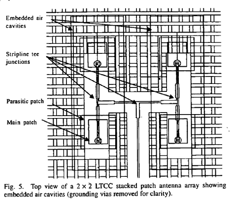
Stacked: Two or more electromagnetically coupled patches are placed on top of one another to increase bandwidth or operating on different frequencies.
Illustrative examples of subject-matter classified in this group:
See: XP00686400,XP000457518
Folded: Folding the patch to reduce its surface cross section resp. to increase its physical length
See: XP1192752, XP6010688, US2003107518, US2002175865
If planar parasitic elements are placed also as side elements then H01Q 19/005 too.
All documents where stacked patches are used.
In patent documents, the following words/expressions are often used as synonyms:
- "stacked patch radiators", "driven and parasitic patch", "upper or top and lower or bottom patch" and "multilayered with upper and lower patches folded"
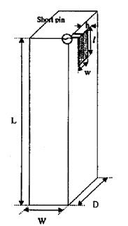
This place covers:
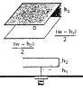
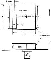
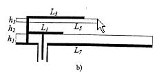
An inverted F antenna is essentially a shorted quarter wavelength long patch. Shorting pins/posts or vertical wall inserted where the surface currents are at a minimum maintain the antenna resonance at the same frequency as a full-size patch, thus size reduction, small size.
Planar inverted L-antenna (PILA) Planar inverted F-antenna (PIFA).
Illustrative example of subject-matter classified in this group:
See: XP1112734, XP963857.
Inverted- L and inverted -F-antennas as wire (not-planar) are in H01Q 9/42 (monopole with folded element).
In this place, the following terms or expressions are used with the meaning indicated:
PILA | Planar Inverted-L Antenna |
PIFA | Planar Inverted-F Antenna |
In patent documents, the following words/expressions are often used as synonyms:
- "hort-circuited" and "planar inverted"
This place covers:
Single-fed circularly polarised (CP) patch antenna: two orthogonal modes are generated by perturbations or modifications to the standard patch geometry; that leads to circular polarisation radiation in the far field; without external network.
Illustrative example of subject-matter classified in this group:
- diagonal-fed nearly square; corner-fed;
- truncated-corners;
- square with diagonal slot, slit or cutout;
- pentagon or triangular patch;
- with stubs extending from the edges or notches inserted at the edge; with loading.
See: XP740145
Circular polarised patch antennas using a single feed, single- or singly-fed.
In this place, the following terms or expressions are used with the meaning indicated:
CP | circular polarised |
RHCP | right hand circular polarized |
LHCP | left hand |
SFCP | singly-fed or one-point feed ,or singly fed |
In patent documents, the following words/expressions are often used as synonyms:
- "RHCP", "right hand circular polarised" and "left hand polarised"
This place covers:
Circular polarised patch with dual feed at two orthogonal points with equal amplitude and 90° phase difference.
Illustrative example of subject-matter classified in this group:
Input signal is split with 90° degree hybrid or Wilkinson power divider in two signals and coupled directly or capacitively coupled two feed points.
See: XP1058724, XP279307.
Keyword for dual polarisation, i.e. polarisation-dual (H01Q) (will/to be converted into Indexing Code /CPC symbol).
In this place, the following terms or expressions are used with the meaning indicated:
CP | fed circular polarised |
This place covers:
Particular tuning means refers here to patch antennas where the resonance frequency or bandwidth may be adjusted/controlled by tuning elements/circuits like switch devices, diodes, varactors, reactive loading, stubs, strips, capacitors, permeability of ferrites, ferroelectric materials, etc.
Illustrative example of subject-matter classified in this group:

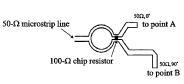
With tuning stub(28); with pin diodes(230,240); with stub line (41);reactive loaded.
See: US2002075190, XP680870.
Comprises patch antennas with controllable tuning elements.
In this place, the following terms or expressions are used with the meaning indicated:
Tunable reactive loading | controllable element which reactance (capacitance or inductance) can be changed |
In patent documents, the following words/expressions are often used as synonyms:
- " tuning / adjusting / controlling resonant frequency or bandwidth" and "variably frequency"
This place covers:
All feedings means which are particular, not standard like coaxial probe-fed or direct coplanar transmission line fed (H01Q 9/0407).
Particular direct coupling:
transmission line with matching circuit and coax probe feed
Illustrative example of subject-matter classified in this group:
Inset-fed; edge- fed; coplanar waveguide fed (CPW).
See:XP336955, XP273716, XP1058725, US4724443
This place does not cover:
Feeding means for circular polarisation |
This group contains documents with particular direct coupling; electromagnetical coupling is in H01Q 9/0457.
In patent documents, the following words/expressions are often used as synonyms:
- " conventional direct contacting feeding", "probe-fed, coaxial, direct probe fed, directly fed" and "coplanar transmission line fed; stripline edge fed, line fed"
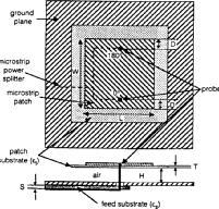
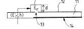
This place covers:
All patch antennas without direct connection of the feed line to the patch, i.e. with non-contacting feeding structures as electromagnetic coupling like:
- proximity, capacitive coupling or
- aperture (slot) coupling
Illustrative example of subject-matter classified in this group:
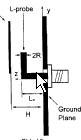

Proximity stripline coupled; L-probe proximity coupled; aperture coupled; CPW (Coplanar Waveguide) coupled.
See: XP1046273, XP895921, XP294631, XP1006617, XP230628, XP1158250.
In this place, the following terms or expressions are used with the meaning indicated:
EMC, EM coupled | electromagnetically coupled -capacitively coupled; proximity coupled, gap coupled, coplanar side coupled - aperture coupled via slot, also via crossed slot, slot-coupled with various shapes |
CPW coupled | coplanar waveguide coupled |
In patent documents, the following words/expressions are often used as synonyms:
- "electromagnetic", "proximity" and "capacitive coupling"
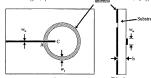
This place covers:
All patch antennas whereby the patch radiator is in the form of an annular ring which shows small size and larger bandwidth as compared to conventional rectangular or circular patches.
Illustrative example of subject-matter classified in this group:
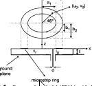
Annular ring proximity/electromagnetically coupled; direct coupled annular elliptical ring.
See: XP1201836, XP951884.
Microstrip-fed slot-ring in H01Q 13/106.
In patent documents, the following words/expressions are often used as synonyms:
- "l microstrip ring", "Annular ring microstrip antenna (ARMSA)", "annular ring patch" and "ring-shaped, annular patch"
This place covers:
Special shaped patch antennas whereby the patch:
- is non-planar e.g. curved; spherical; three dimensional shape;
- stepped or
- wedge shaped i.e. mounted on wedge-shaped dielectric; slanted; sloping patch).
Illustrative example of subject-matter classified in this group:

Non-planar; stepped; wedge shaped; cylindrical.
See: XP680870, EP1026774, US6879290, US2003210190, US200289455, EP806810.
Comprises also patches wraparound cylindrical surfaces; also patches with shaped ground planes.
In patent documents, the following words/expressions are often used as synonyms:
- "l microstrip ring", "annular ring microstrip antenna (ARMSA)" , "staircase" and "slope"
This place covers:
Patches with means for reducing spurious modes which cause cross polarization i.e. the unwanted other polarization e.g. the orthogonal linear or circular polarization caused by a second mode resp. by orthogonal currents on the patch.
Illustrative example of subject-matter classified in this group:
Patch with plurality of parallel conductive strips; with dual-probe fed (balanced feed) or two shorting pins.
This place covers:
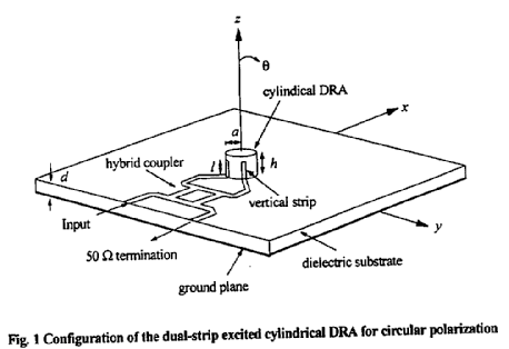
Consists of a volume of a dielectric material disposed on or close to a grounded substrate, with energy transferred by way of monopole probes inserted into the dielectric or by way of aperture feeds provided in the ground substrate. In a dielectric resonator antenna (DRA) it is the dielectric material that radiates when excited by the feed.
The resonant characteristics depend upon the shape and size of the volume of dielectric, the material >>1, the shape , size and position of the feeds thereto and also on the shape, size and position of the ground plane.
Illustrative example of subject-matter classified in this group:
See: US6198450, WO2004017461.
Quite similar modifications as for patch antennas in respect to feeding (probe-fed or slot/ aperture fed), increasing of bandwidth and tuning of resonant frequency.
USPTO classifies in H01Q 1/38 (/IC).
A dielectric loaded antenna (DLA) is a patch antenna in which the conductive radiating element is encased in a dielectric material for modifying the resonance characteristics.
In this place, the following terms or expressions are used with the meaning indicated:
DRA | dielectric resonator antenna; |
HDA | high dielectric antenna |
This place covers:
Using two feed points, or using coupled modes.
Illustrative example of subject-matter classified in this group:
This place covers:
A microstrip antenna of rectangular shape with its width much smaller than its length. A resonator made with a narrow conductor strip, i.e. making L resonant and W very thin.
Illustrative example of subject-matter classified in this group:
This place does not cover:
Patch antennas |
In patent documents, the word/expression in the first column is often used instead of the word/expression in the second column, which is used in the classification scheme of this place:
strip dipole | "printed dipole", "monopole strip" and "microstrip antenna with dipole resonator" |
This place covers:
Originally used for top-set TV antenna with adjustable angle between telescopic dipole arms.
Illustrative example of subject-matter classified in this group:
Inactive.
Inactive.
This place covers:
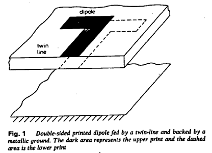
A dipole consist of two collinear and contiguous metallic rods or tubes with the feed between or of two conical conductors, typical hollow, or of strips or triangles printed on a thin dielectric substrate: maximum radiation everywhere at right angles, zero along the length.
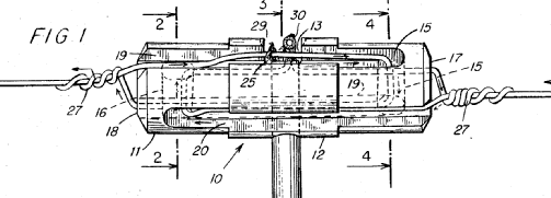
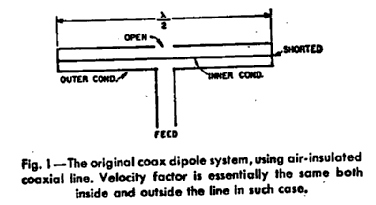
Sleeve-dipole antenna: An antenna surrounded in its central portion by a coaxial conducting sleeve.
Illustrative example of subject-matter classified in this group:
This place does not cover:
with a plurality of divergent straight elements, e.g. V-dipole, X-antenna; with a plurality of elements having mutually inclined substantially straight portions |
This place covers:
Typically used for pattern which is omnidirectional in azimuth.
Illustrative example of subject-matter classified in this group:
This place covers:
Collinear, taht is axis lying in a straight line.
Illustrative example of subject-matter classified in this group:
This place does not cover:
Conical, cylindrical, cage, strip, gauze, or like elements having an extended radiating surface; Elements comprising two conical surfaces having collinear axes and adjacent apices and fed by two-conductor transmission lines |
This place covers:
Cylindrical dipole: dipole with cylindrical arms.
Illustrative example of subject-matter classified in this group:
This place covers:
This actually pertains to how the currents on the dipole are excited.
Illustrative example of subject-matter classified in this group:
This place covers:
An antenna composed of two or more parallel, closely-spaced dipole antennas connected together at their ends with one of the dipole antennas fed at its center and the others short-circuited at their centers.
Illustrative example of subject-matter classified in this group:
This place does not cover:
Resonant loop antennas |
This place covers:
Only pertains to the shape of the dipole.
Illustrative example of subject-matter classified in this group:
This place covers:
An antenna consisting of one or more conducting wires or tapes arranged as a spiral.
Illustrative example of subject-matter classified in this group:
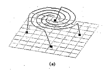
Spiral antennas are usually classified according to the shape of the surface to which they conform (for example. conical or planar spirals). and according to the mathematical form (for example. equiangular or archimedean).
This place covers:
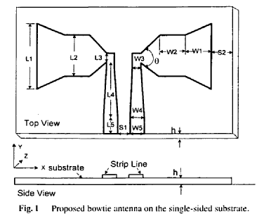
Basically any dipole geometry for which the dipole arms have a specific shape: bow-tie, bicone.
Illustrative example of subject-matter classified in this group:
This place does not cover:
Waveguide horns or mouths; slot antennas |
This place covers:
Dipole printed on a dielectric substrate; printed -, dielectric dipole.
Illustrative example of subject-matter classified in this group:
This place does not cover:
Patch antennas | |
Microstrip dipole antennas |
This place covers:
An antenna, constructed above an imaging plane, that produces a radiation pattern approximating that of an electric dipole in the half-space above the imaging plane. The monopole requires a ground plane or counterpoise which may be the equipment enclosure. The monopole is a dipole with half of its length replaced by an "image created by an infinite (or very large) ground plane; also with base or centre loading.
Coaxial monopole antenna: An antenna comprised of an extension to the inner conductor of a coaxial line and a radiating sleeve that in effect is formed by folding back the outer conductor of the coaxial line; sleeve-monopole/sleeve stub antenna.
Illustrative example of subject-matter classified in this group:
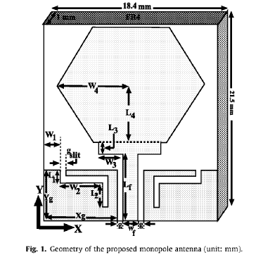
This place does not cover:
with feed to end of elongated active element, e.g. unipole |
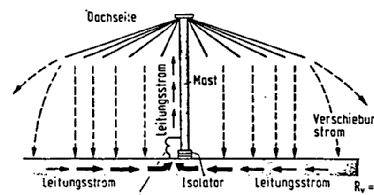
This place covers:
Mechanical rigidity required.
Illustrative example of subject-matter classified in this group:
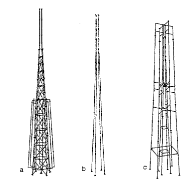
This place covers:
A vertical monopole with an additional metallic structure at the top intended to increase the effective height of the antenna and to change its input impedance.
Illustrative example of subject-matter classified in this group:
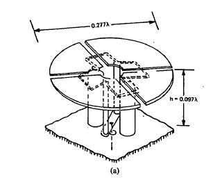
In patent documents, the following words/expressions are often used as synonyms:
- "flat-top antenna", "end capacitor", "top-loaded vertical antenna" and "umbrella antenna"
This place covers:
As series-fed or shunt-fed vertical antenna whereby the antenna is insulated from ground and whose feed line connects between ground and the lower end of the antenna or the antenna is connected directly to ground and whose feed line connects between ground and a point suitably positioned above.
Illustrative example of subject-matter classified in this group:
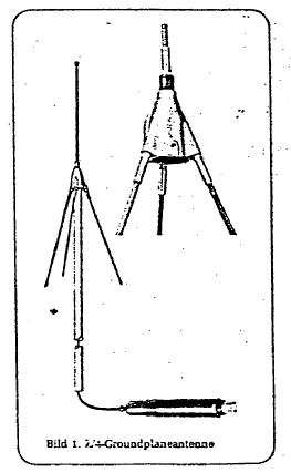
This place does not cover:
with counterpoise comprising elongated elements coplanar with the active element |
This place covers:
Basically any monopole geometry for which the radiator has a specific shape: conical, planar-triangular, etc.
Illustrative example of subject-matter classified in this group:
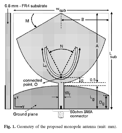
This place covers:
A monopole antenna formed from half of a folded dipole with the unfed element(s) directly connected to the imaging plane.
Inverted- L antenna: a short monopole as vertical element and a wire horizontal element (quarter wavelength) attached at the end of the monopole.
Inverted -F antenna: a small I-L element is attached at the end of the vertical element of the ILA.
Illustrative example of subject-matter classified in this group:
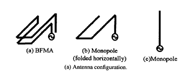
This place covers:
Turkish sabre shape.
Illustrative example of subject-matter classified in this group:
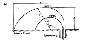
This place covers:
Illustrative example of subject-matter classified in this group:
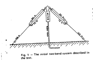
Remark:
If the straight elements have different length, see also H01Q 21/30, since multiband operation is obtained in this way when fed at the same point (see reference below).
This place does not cover:
Combinations of two or more active elements | |
Turnstile antennas |
This place covers:
Illustrative example of subject-matter classified in this group:
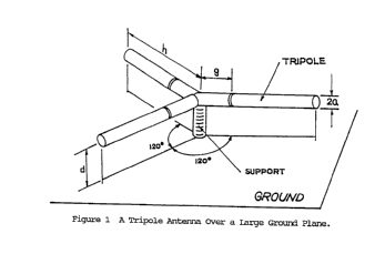
See also H01Q 21/30 if the elements are joined to the same feed point.
This place covers:
An antenna consisting of one or more wires whose length is large in respect to the wavelength (long-wire antennas). Two types:
- non-resonant (non-periodic; terminated) and
- resonant antennas with standing waves.
Long-wire antenna: A wire antenna that, by virtue of its considerable length in comparison with the operating wavelength, provides a directional pattern.
This place does not cover:
Leaky waveguides antennas, slot antennas |
Attention is drawn to the following places, which may be of interest for search:
Combinations of active elements with secondary devices to give desired directional characteristic | |
Antenna arrays or systems |
This place covers:
Travelling-wave antennas means antennas whose excitation has a quasiuniform progressive phase, as the result of a single feeding wave traversing its length in one direction only. Terminated in a resistance.
Illustrative example of subject-matter classified in this group:
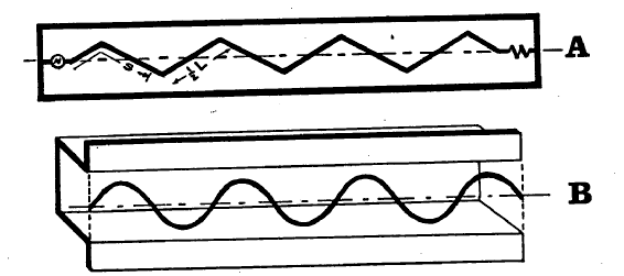
This place does not cover:
Yagi antennas |
This place covers:
As fishbone antenna: an end-fire, travelling wave antenna.
Illustrative example of subject-matter classified in this group:
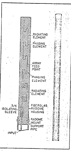
This place does not cover:
rhombic antennas, V-antennas | |
Helical antennas | |
Log-periodic antennas |
This place covers:
Rhombic antenna: composed of long wire radiators arranged in such a manner that they form the sides of a rhombus.
V-antenna: A V-shaped arrangement of two conductors, balanced fed at the apex, with induced angle, length and apex height above the earth chosen so as to give the desired directive properties to the radiation pattern.
Illustrative example of subject-matter classified in this group:
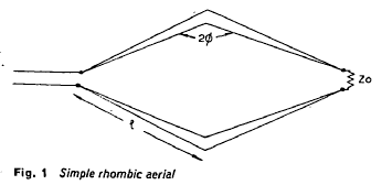
This place covers:
An antenna consisting of a single conductor or multiple conductors wound into a helical shape, whereby the helix circumference is of the order of one wavelength; radiating in axial mode i.e. along the helix axis.
- monofilar, unifilar or
- bifilar, quadrifilar , octofilar or multifilar also in backfire configuration
Illustrative example of subject-matter classified in this group:
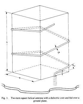
This place covers:
Windings are on a (part of a) cone; tapered geometries.
Illustrative example of subject-matter classified in this group:
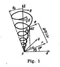
This place covers:
Illustrative example of subject-matter classified in this group:
This place covers:
A class of antennas having the structural geometry such that its impedance and radiation characteristics repeat periodically as the logarithm of the frequency.
Illustrative example of subject-matter classified in this group:
This place does not cover:
periodic aerials, e.g. length or spacing of elements according to a given law |
This place covers:
Illustrative example of subject-matter classified in this group:
This place covers:
When the long-wire antenna is open at its end standing waves can be formed when the length is a multiple of the wavelength.
Illustrative example of subject-matter classified in this group:
This place covers:
Illustrative example of subject-matter classified in this group:
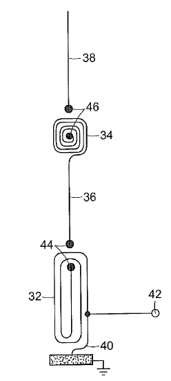
This place does not cover:
V-antennas |
This place covers:
Illustrative example of subject-matter classified in this group:
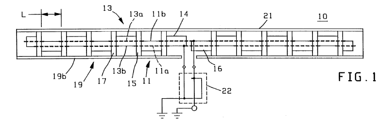
This place covers:
Illustrative example of subject-matter classified in this group:
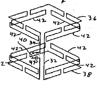
This place covers:
A V-shaped arrangement of two horizontally arranged long-wire antenna.
In essence, it is a centre-fed dipole for which the arms are collinear; this has an effect on the impedance seen at the feedpoint.
Illustrative example of subject-matter classified in this group:
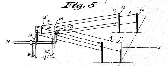
This place covers:
Horn radiator: a waveguide section in which the cross section increases towards an open end that is the aperture.
Slot antenna: a radiating element formed by a slot in a conducting surface.
Leaky wave antenna: an antenna that couples power in small increments per unit length, either continuously or discretely, from a traveling wave structure to free space.
Attention is drawn to the following places, which may be of interest for search:
Multimode aerials |
This place covers:
An antenna consisting of a waveguide section in which the cross sectional area increases towards an open end that is the aperture.
Illustrative example of subject-matter classified in this group:
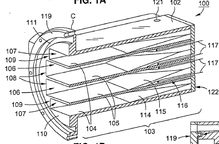
This place covers:
A hybrid-mode horn antenna produced by cutting narrow transverse grooves of specified depth in the interior walls of the horn.
Illustrative example of subject-matter classified in this group:
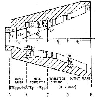
This place does not cover:
Manufacturing details | |
Waveguide mouth antenna with corrugated flange |
This place covers:
Depth of the corrugations is not constant: e.g. for dual frequency operation, the depth still is a quarter wave at the respective frequencies.
Illustrative example of subject-matter classified in this group:
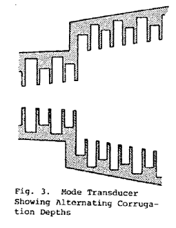
This place covers:
Rectangular, pyramidal, elliptical.
Illustrative example of subject-matter classified in this group:
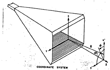
This place does not cover:
of non-circular cross-section |
This place covers:
Normally slots are disposed in the wall of a waveguide. Flanges are attached in order to increase directivity.
Illustrative example of subject-matter classified in this group:
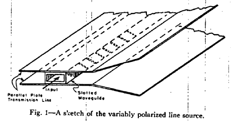
This place does not cover:
Biconical horns |
This place covers:
Converters from linear polarisation to circular and vice versa; linear to linear (polarisation rotator), or from linear to elliptical.
Illustrative example of subject-matter classified in this group:
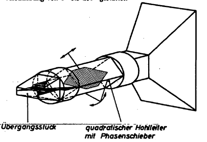
This place does not cover:
radiating a circularly polarised wave | |
takes precedence; polarisation converters | |
in a waveguide |
This place covers:
Multiple modes are used either for matching, or for cross-polarisation reduction, or any other aim.
Illustrative example of subject-matter classified in this group:
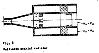
This place does not cover:
Horns using higher mode of propagation | |
multiple beam |
In patent documents, the following words/expressions are often used as synonyms:
- "hybrid mode", "dual mode", "potter horn" and "dompound horn antenna"
This place covers:
Receiving or transmitting orthogonal polarised signals; polarisation filter which separates orthogonal polarisations within the same band; OMT.
Illustrative example of subject-matter classified in this group:
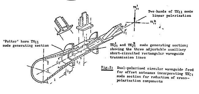
This place does not cover:
Orthomode transducers |
Attention is drawn to the following places, which may be of interest for search:
With combining or separating polarisations |
This place covers:
Chokes are either for VSWR reduction, or for sidelobe reduction.
Illustrative example of subject-matter classified in this group:
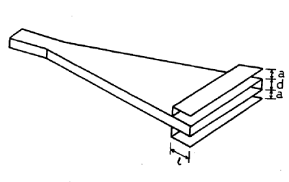
This place covers:
Ridges in pyramidal horns to expand frequency range of operation; ridge-loaded.
Illustrative example of subject-matter classified in this group:
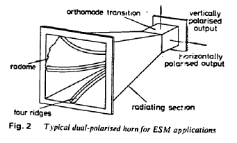
This place does not cover:
slot-line radiating ends |
This place covers:
Any manufacturing process related to horns is to be classified here.
Illustrative example of subject-matter classified in this group:
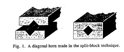
This place covers:
Any manufacturing process related to corrugated horns is to be classified here.
Illustrative example of subject-matter classified in this group:
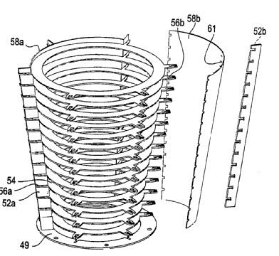
This place covers:
An antenna consisting of two conical horns having a common axis and vertex.
Illustrative example of subject-matter classified in this group:
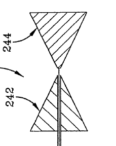
This place does not cover:
biconical dipoles comprising two conical surfaces having collinear axes and adjacent apices and fed by a two-conductor transmission line |
This place covers:
An open waveguide with round or square opening.
Illustrative example of subject-matter classified in this group:
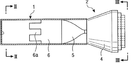
This place does not cover:
Waveguide mouths (horns |
This place covers:
Chokes for either for VSWR reduction, or for sidelobe reduction.
Illustrative example of subject-matter classified in this group:
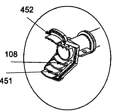
This place covers:
Open-ended coaxial line: current minimum and voltage maximum at the end; standing waves by superposition of running and reflected wave TEM-mode coaxial line as feeding a radiating annular slot.
Microstrip line, open-ended or with short -circuited edge.
Illustrative example of subject-matter classified in this group:
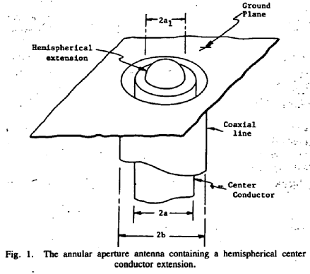
A microstrip-line as open-ended or with a short-circuited edge becomes a microstrip antenna when its length is half-wave resp. quarter-wave and its width less than a wavelength, then it behaves as a half wave open-ended transmission line resonator with radiating edges.
JPO classifies this antenna type here; however we classify said type as a resonant structure in H01Q 9/0407 and subgroups.
This place covers:
In the form of tapered or flared slot antenna: Are a type of travelling-wave antenna where a travelling wave propagates along the surface of the antenna taper with a phase velocity less than the speed of light. Under this condition, endf ire radiation results.
Illustrative example of subject-matter classified in this group:
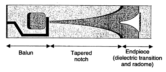
In patent documents, the following abbreviations are often used:
TSA | tapered slot antenna |
In patent documents, the following words/expressions are often used with the meaning indicated:
"Vivaldi antenna" | "endfire slotline". |
This place covers:
A radiating element formed by a slot in a conducting surface; in its simplest form as thin rectangular slot having a length of lam bda/2 or lambda cut in an extended thin flat sheet of metal excited by a voltage source to the opposite edges of the slot; complementary to dipole.
Slot, usually a half-wavelength long, is cut from a large (relative to the slot length) metal plate. The center conductor of a coaxial cable is connected to one side of the slot, the outside conductor is connected to the other side of the slot; the feed-point can be off-center to provide 50- Ohm impedance.
Illustrative example of subject-matter classified in this group:
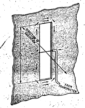
See: XP010608951.
Normally speaking, a slot is a cut for which the wavelength is around half a wavelength, due to the boundary conditions of the electric field.
A notch typically has an open end, and this causes that its minimum length is around a quarter wavelength.
In the field, slit is used to denominate both types of radiators (slot and notch).
In patent documents, the following words/expressions are often used with the meaning indicated:
"votch- or slit antenna" | "annular - or ring slot antenna". |
This place covers:
Basically impedance loading is used for tuning the antenna; here it can be a reactive load (L/C) or a resistive one (R), contrary to the definition of the class.
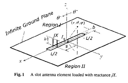
Attention is drawn to the following places, which may be of interest for search:
with variable reactance for tuning the antenna |
This place covers:
Slot in conducting surface bonded to a thin grounded dielectric substrate.
Illustrative example of subject-matter classified in this group:
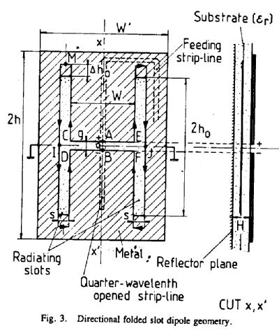
This place does not cover:
Microstrip slot antennas (patch antenna elements) |
The geometries can be the following: narrow slot/slit, circular slot, annular -, ring- ,slot-ring antenna; spiral, bow-tie; folded slot antenna.
This place covers:
A cylindrical waveguide with a continuous slot in its wall; the geometry can be such it is not continuous, but curved or wave, in order to change the excitation law along the longitudinal extent of the waveguide.
Examples: as narrow slot/slit, circular slot, annular -, ring- ,slot-ring antenna; spiral, bow-tie; folded slot antenna.
Illustrative example of subject-matter classified in this group:
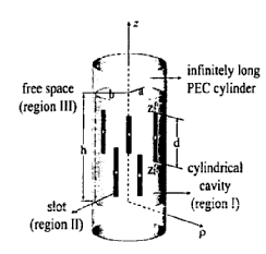
This place covers:
Illustrative example of subject-matter classified in this group:
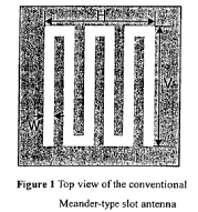
This place covers:
Illustrative example of subject-matter classified in this group:
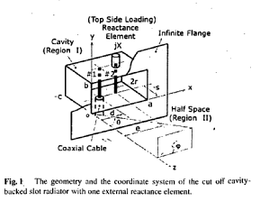
This place does not cover:
ongitudinally slotted cylinder |
This place covers:
An antenna that couples power in small increments per unit length, either continuously or discretely, from a travelling wave structure to free space; a guiding structure that leaks power all along its length; typically 20 times lambda; remaining power in matched load.
Illustrative example of subject-matter classified in this group:
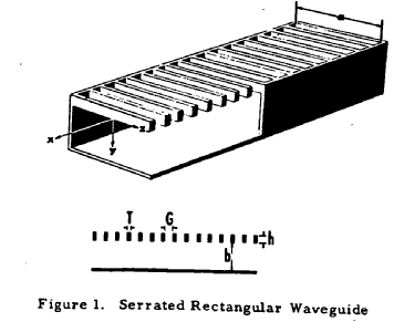
Attention is drawn to the following places, which may be of interest for search:
varying the phase velocity | |
Near-field transmission systems using the near field of leaky cables |
This place covers:
The radiation happens via periodic slits/slots or holes in the outer conductor; variation of slot length, width and inclination angle.
Illustrative example of subject-matter classified in this group:
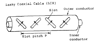
Attention is drawn to the following places, which may be of interest for search:
For concentric or coaxial cables | |
Near-field transmission systems using the near field of leaky cables |
Radiating coaxial cable.
This place covers:
A microstrip transmission line is normally non radiating but can be made to radiate:
- by a series of patch antennas connected by a microstrip line;
- by a series of radiators, resonant or not, coupled by proximity to the microstrip line;
- bending the strip conductor ( meandered periodically, sinusoidal, trapezoidal, zigzag).
Illustrative example of subject-matter classified in this group:
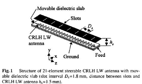
In patent documents, the following words/expressions are often used with the meaning indicated:
"microstrip travelling wave" | "microstrip leaky wave". |
This place covers:
Leaky waveguide with long or narrow slits/slots or holes.
Illustrative example of subject-matter classified in this group:
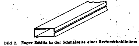
This place does not cover:
Longitudinal slot in boundary wall of waveguide or transmission line |
This place covers:
An antenna that employs a shaped dielectric rod as the electrically significant part of a radiating element. excited by a circular or rectangular waveguide; a surface wave travels along the rod till the end where it radiates into space.
The polyrod antenna is a notable example of the dielectric rod when constructed of polystyrene. Ferrod made of ferrite material.
Illustrative example of subject-matter classified in this group:
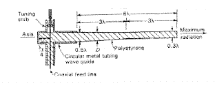
This place does not cover:
constituted by a dielectric or ferromagnetic rod or pipe |
This place covers:
A surface wave radiates only at discontinuities, i.e. these discontinuities are therefore a requirement.
Illustrative example of subject-matter classified in this group:
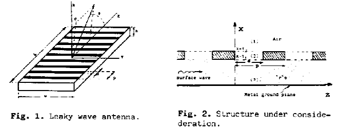
This place covers:
Periodic modulation of the guiding structure: e.g. periodic metal strips Guiding structure: dielectric waveguide or dielectric image guide.
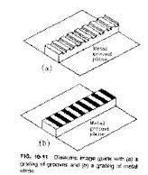
Discontinuities by:
- grating by periodic array of grooves or b) grating of periodic array of metal strips;
- continuous transverse stub;
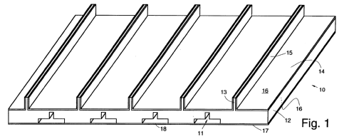
- non-radiative dielectric guide/waveguide (NRD) as antenna as leaky NRD.
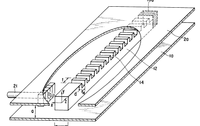
Attention is drawn to the following places, which may be of interest for search:
Elements, conductive elements forming artificial dielectric |
This place covers:
Lenses, reflectors and polarising devices per se or in combination with a classification in H01Q 19/00 and subgroups, H01Q 21/00 and subgroups or H01Q 25/00 and subgroups if aspects of the lens, reflector etc. per se are also relevant.
This place covers:
This class and subclasses emphasize the frequency dependence on impedance and other properties of the device.
This place does not cover:
Devices acting selectively as reflecting surface, as diffracting or as refracting device, e.g. frequency filtering or angular spatial filtering devices |
This place covers:
Perforated plates, where the apertures can have any generalised shape.
Illustrative example of subject-matter classified in this group:
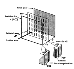
This place covers:
Normally switches or variable impedance are used for the tuning or reconfiguration.
Illustrative example of subject-matter classified in this group:
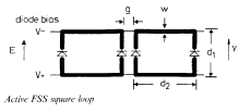
This place covers:
Multiple layers of (different) FSS's are present.
Illustrative example of subject-matter classified in this group:
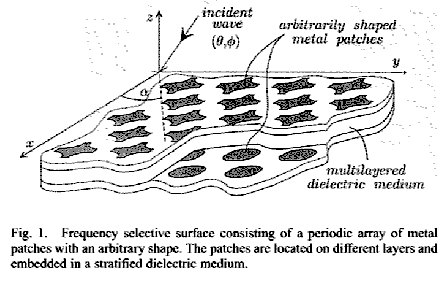
This place covers:
As used in beam waveguides.
Illustrative example of subject-matter classified in this group:
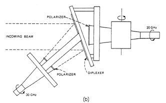
This place does not cover:
used for beam splitting or combining, e.g. acting as a quasi-optical multiplexer |
This place covers:
This class emphasizes the materials used: chiral materials, superconducting materials, etc.
Illustrative example of subject-matter classified in this group:
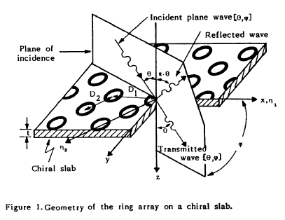
This place covers:
For example randomised FSS cells based on genetic algorithms.
Illustrative example of subject-matter classified in this group:
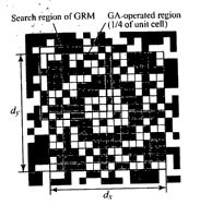
This place covers:
Illustrative example of subject-matter classified in this group:
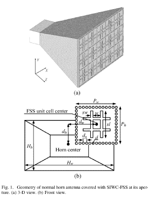
This place covers:
Emphasizes on band gap materials, in any application.
Illustrative example of subject-matter classified in this group:
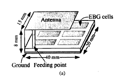
This place covers:
Emphasis is on reconfigurability and tunability.
Illustrative example of subject-matter classified in this group:
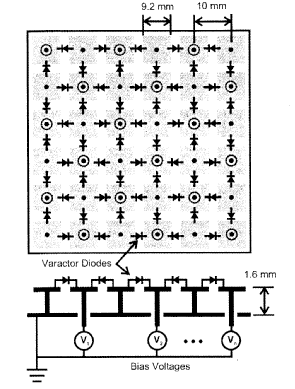
This place covers:
Either corrugations in a single direction, or in two orthogonal directions; may be filled with dielectric material.
Illustrative example of subject-matter classified in this group:
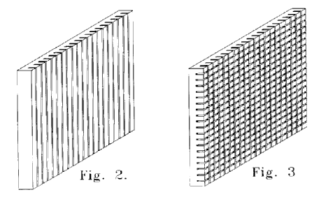
This place covers:
Or similar structures to these mushroom elements: triangular/square/circular shapes.
Illustrative example of subject-matter classified in this group:
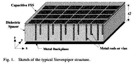
This place covers:
These materials do not exists in nature, but they are artificial, and strongly frequency dependent.
Illustrative example of subject-matter classified in this group:
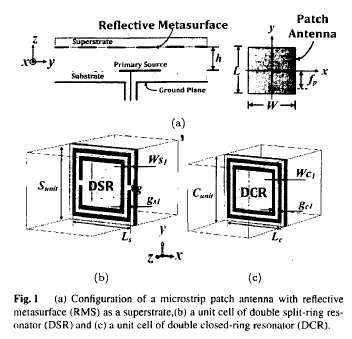
This place covers:
ANY fractal shape (sierpinski/peano/ ...).
Illustrative example of subject-matter classified in this group:
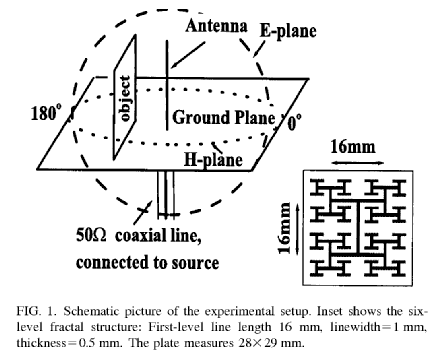
This place covers:
Lens, electromagnetic. A three-dimensional structure, through which electromagnetic waves can pass, possessing an index of refraction that may be a function of position and a shape that is chosen so as to control the exiting aperture illumination to transform a spherical wavefront.
- lens constructed of dielectrics;
- of metallic or artificial dielectrics.
Examples: Wire -grid lens, that is constructed of wire grids, in which the effective index of refraction (path delay) is locally controlled by the dimensions and the spacing of the wire grid; zoned lenses, that is various portions (zones or steps) form a discontinuous surface such that a desired phase distribution of the aperture illumination is achieved.
Illustrative example of subject-matter classified in this group:
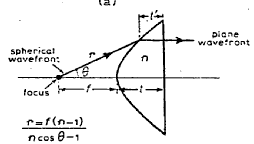
This place covers:
Metal-plate lens using parallel metal plates, spaced a fraction of a wavelength apart; also use of parallel wires.
Illustrative examples of subject-matter classified in this group:
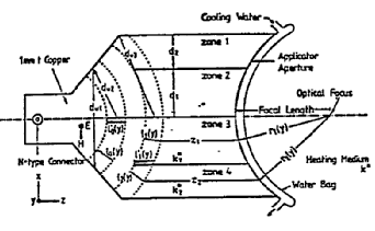
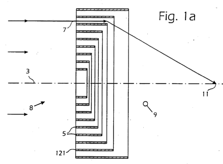
This place covers:
Consisting of an array of waveguide tubes or transmission lines in which focusing is achieved by means of phase correction introduced by the tube or line length or the tube section profile.
Illustrative example of subject-matter classified in this group:
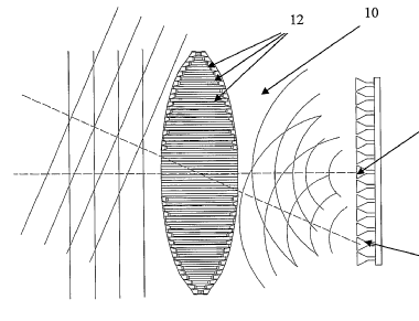
Waveguide-lens, Bootlace lens antenna consists of an input array connected to an output array by transmission lines; Rotman lens.
This place covers:
Conventional dielectric lenses: Materials: made of thermoplastics, styropor, Rexolite, teflon, styrofoam, foamed glas, polystyrene, plexiglas.
Luneberg lens: A lens with a circular cross section having an index of refraction varying only in the radial direction (e.g. two or more concentric spheres).
Illustrative example of subject-matter classified in this group:
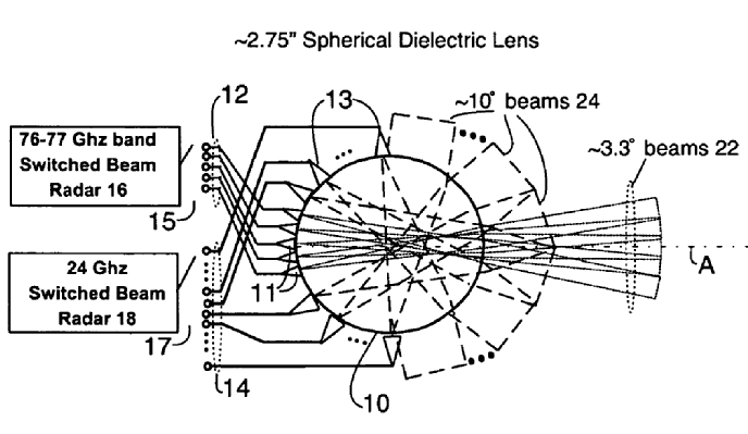
This place covers:
Artificial dielectric by distribution of conducting or non-conducting elements in a medium of relatively low dielectric constant: lightweight in respect to solid dielectric lenses.
Illustrative example of subject-matter classified in this group:
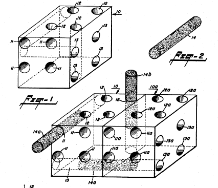
Attention is drawn to the following places, which may be of interest for search:
leaky-waveguide antennas |
This place covers:
For example: dielectric microwave lens or prism with polarisation filter located on one side of the lens.
Illustrative example of subject-matter classified in this group:
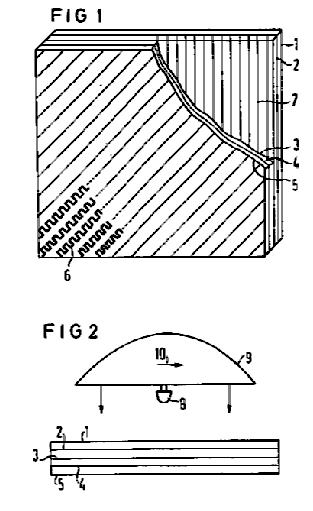
This place does not cover:
functioning also as polarisation filter |
This place covers:
Basically anything that reflects, i.e. the reflectors proper.
Illustrative example of subject-matter classified in this group:
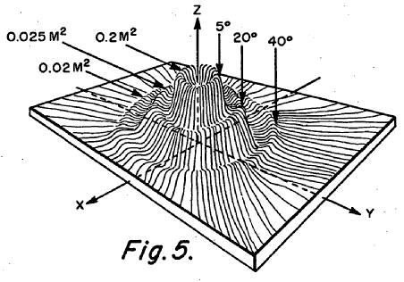
This place does not cover:
electromagnetic shields |
Attention is drawn to the following places, which may be of interest for search:
Radar-reflecting targets in general |
This place covers:
Any manufacturing method goes here.
Illustrative example of subject-matter classified in this group:
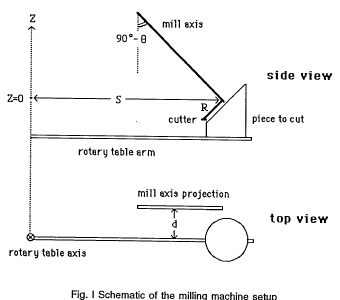
This place covers:
Insulating material fulfills the role of support or backing structure.
Illustrative example of subject-matter classified in this group:
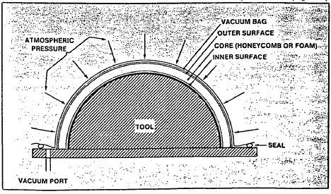
This place covers:
Illustrative example of subject-matter classified in this group:
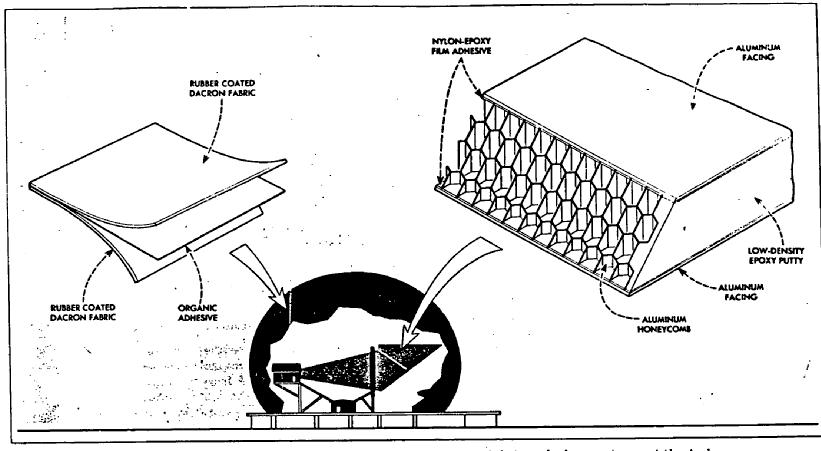
This place covers:
Consists of thousands of fine wire clippings, paper backed metal foils or carbon fibers; the chaff acts as dipoles that reflect a wide range of radar frequencies.
Illustrative example of subject-matter classified in this group:
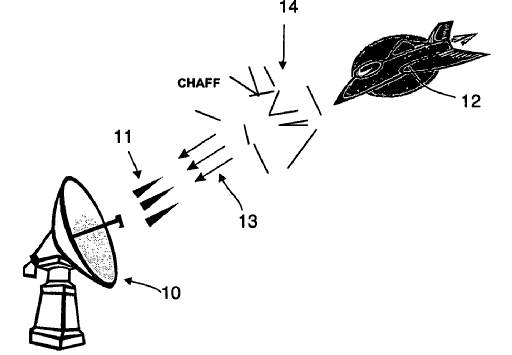
This place does not cover:
missiles of the signal type provided with means for disseminating radar-reflecting chaff |
This place covers:
Shaped reflector, reconfigurable, reflector surface control, deformable reflector surface; zoned or stepped reflector.
Illustrative example of subject-matter classified in this group:
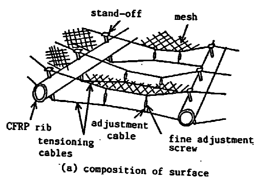
This place does not cover:
for scanning | |
aerials or aerial systems providing multiple beamwidths |
This place covers:
For example a reflect-array where the individual elements are subject to weighting in amplitude and phase.
Illustrative example of subject-matter classified in this group:
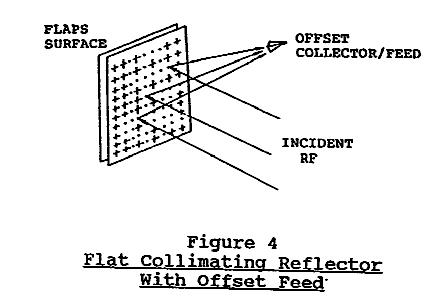
This place does not cover:
with means for varying the reflecting properties |
This place covers:
Paraboloidal, hyperboloidal, ellipsoidal.
Illustrative example of subject-matter classified in this group:
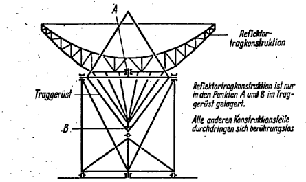
This place covers:
For example using separate panels and hinges.
Illustrative example of subject-matter classified in this group:
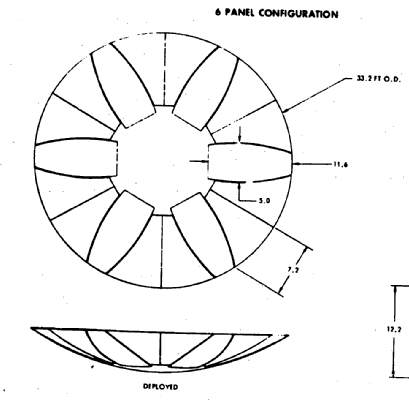
Attention is drawn to the following places, which may be of interest for search:
In patent documents the following words are often used:
Unfurlable/ furlable; deployable; foldable; erectable, fold/unfold.
This place covers:
Illustrative example of subject-matter classified in this group:
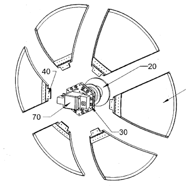
This place covers:
Normally an inflatable carrier is used, which ruggedizes, e.g. vulcanisation in outer space.
Illustrative example of subject-matter classified in this group:
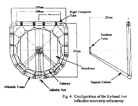
This place covers:
For example earth station antenna need to be made with panels, as otherwise they are too big.
Illustrative example of subject-matter classified in this group:
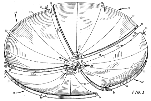
This place does not cover:
composed of a plurality of rigid panels |
This place covers:
Illustrative example of subject-matter classified in this group:
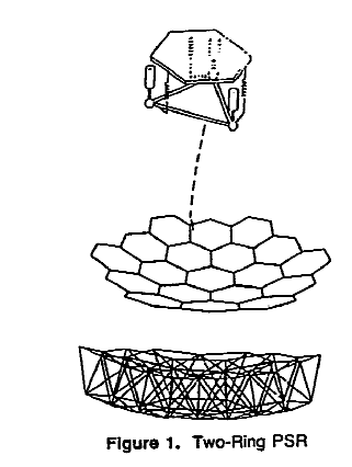
This place covers:
The gap causes scattering, and this needs to be prevented; normally conducting tape is used to cover the gap.
Illustrative example of subject-matter classified in this group:
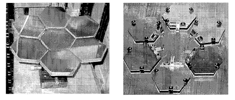
This place covers:
Metallic mesh as a fabric with a supporting structure, e.g. truss structure shaped by a cable network: umbrella reflector.
Illustrative example of subject-matter classified in this group:
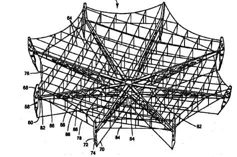
In patent documents, the following words/expressions are often used as synonyms:
- "mesh net", "pliant metal gauze", "cloth-like material" and "pliant reflective material"
This place covers:
A reflecting object consisting of two or three mutually intersecting conducting flat surfaces.
Type of a retroreflector (large echoes); used as emergency signalling device; passive marker; linear polarisation rest unchanged but the sense of circular polarisation is changed after reflection.
Also used as a reference target for radar calibration.
Illustrative example of subject-matter classified in this group:
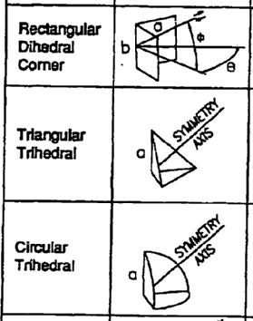
This place does not cover:
comprising plurality of mutually inclined plane surfaces, e.g. corner reflector |
This place covers:
For example inflatable corner reflector.
Illustrative example of subject-matter classified in this group:
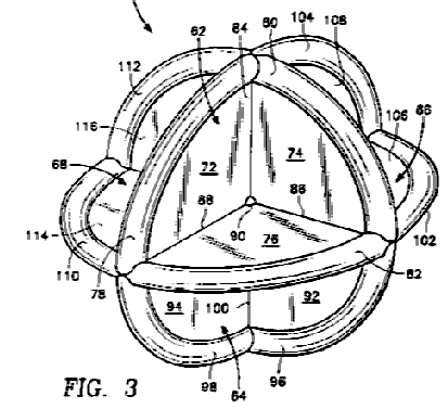
This place covers:
Additional function as a polarisation sensitive reflector.
For example double gridded reflector.
Illustrative example of subject-matter classified in this group:
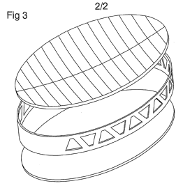
Attention is drawn to the following places, which may be of interest for search:
in combination with polarising devices |
In this place, the following terms or expressions are used with the meaning indicated:
PSS | Polarisation Sensitive Surface |
This place covers:
For example: lens reflector: (part of) a lens mounted on a reflecting surface.
Illustrative example of subject-matter classified in this group:
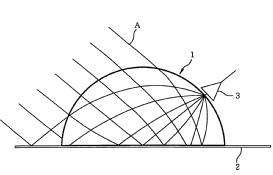
This place covers:
For converting from one into another polarisation, e.g. meanderline polariser.
Illustrative example of subject-matter classified in this group:
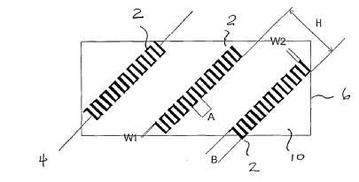
This place does not cover:
devices functioning simultaneously both as polarisation filters and as refracting or diffracting devices or as reflectors |
In patent documents, the following words/expressions are often used as synonyms:
- "polarizer", "polarisator", "polarisation transformer" and "polarisation converter"
This place covers:
For transforming one polarisation into another one (and back): reciprocity.
Illustrative example of subject-matter classified in this group:
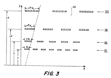
In patent documents, the following words/expressions are often used as synonyms:
- "polarizer", "polarisator", "polarisation transformer" and "polarisation converter"
This place covers:
For example: meanderline converters, or dielectric quarter wave plate inside waveguide, under 45 degrees.
Illustrative example of subject-matter classified in this group:
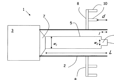
This place does not cover:
guided wave |
This place covers:
For example: polarisation rotator, Faraday rotator.
Illustrative example of subject-matter classified in this group:
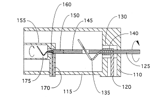
This place does not cover:
guided wave |
This place covers:
A polarisation sensitive device consisting of unidirectional planar gratings which rotate the state of polarisation.
Illustrative examples of subject-matter classified in this group:
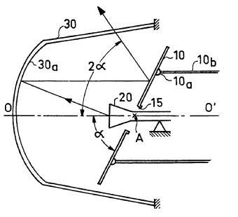
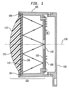
This place does not cover:
combination with a polarisation filter in dual reflector antennas |
This place covers:
There are absorptive and reflective absorbers. In the absorptive absorbers RF energy is transferred into heat, whereas in the reflective absorbers the incident wave directs the RF energy away from the subject to be protected.
Illustrative example of subject-matter classified in this group:
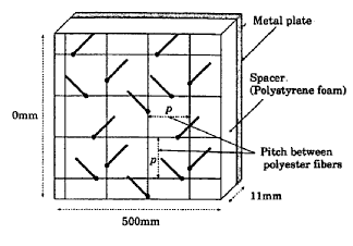
Anechoic chambers are in G01R 29/105.
This place covers:
For example rim loading for a reflector antenna to lower sidelobes.
Illustrative example of subject-matter classified in this group:
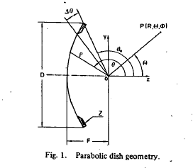
This place covers:
For example chiral type material.
Illustrative example of subject-matter classified in this group:
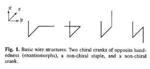
This place covers:
Focuses on the material properties in order to improve the losses.
Illustrative example of subject-matter classified in this group:
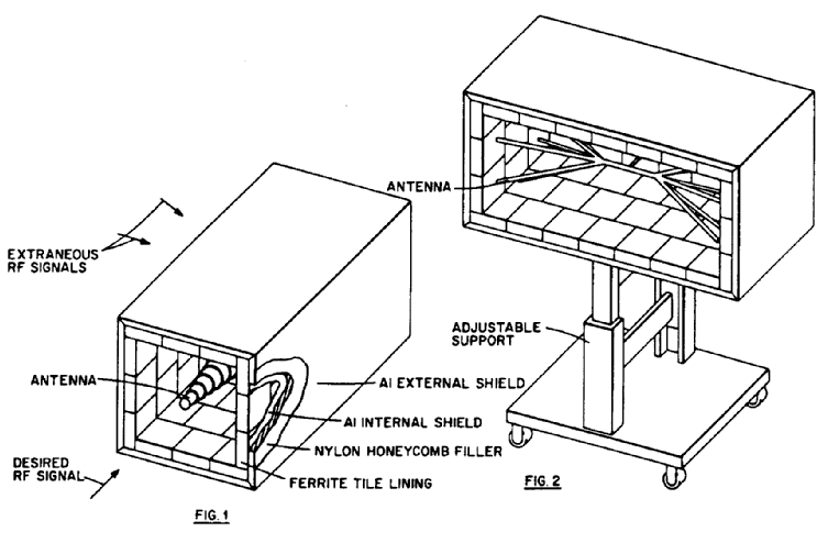
This place does not cover:
flake-like | |
using non-directional dissipative particles, e.g. ferrite powders |
This place covers:
Also combination of optical camouflage, IR camouflage and RF absorbing material.
Illustrative example of subject-matter classified in this group:
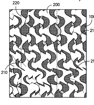
This place covers:
Typically one studies the effect of something, e.g. geometrical arrangement, chemical composition, on the properties of the absorber; largely experimental.
Illustrative example of subject-matter classified in this group:
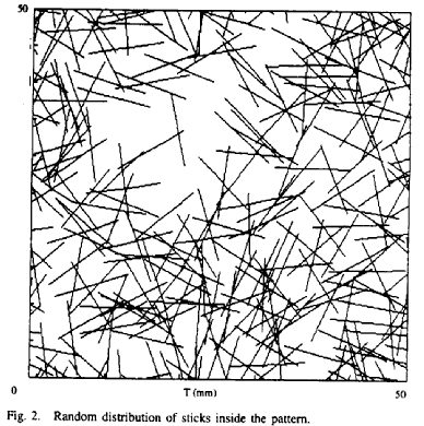
This place covers:
Focusing on the geometrical shapes of the absorbers, e.g. wedge, tile, pyramid, truncated pyramid.
Illustrative examples of subject-matter classified in this group:
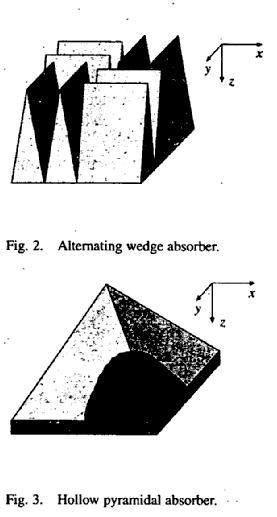
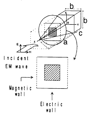
This place does not cover:
with a particular shape |
This place covers:
As Lens antennas and Reflector antennas, i.e. a primary radiator with a lens or reflector as secondary radiators.
This place does not cover:
Combination of horns with slotted waveguide array |
This place covers:
Parasitic element is a radiating element that is not connected to the feed lines of an antenna but affects the radiation pattern.
Only relates to patch antennas.
Illustrative examples of subject-matter classified in this group:
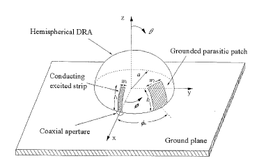
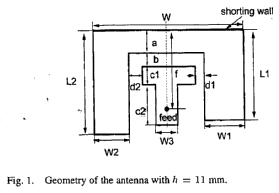
This place covers:
Illustrative example of subject-matter classified in this group:
This place does not cover:
fastening of an element on a boom |
Inactive.
This place covers:
Grating lobes, that is undesired sidelobes in the radiation pattern; e.g. edge scattering, scattering at struts, etc.
Illustrative example of subject-matter classified in this group:
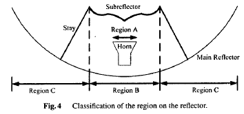
This place covers:
Rim loading, rim shaping.
Illustrative example of subject-matter classified in this group:
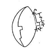
This place covers:
Shaping of struts; covering of struts with absorbing material.
Illustrative example of subject-matter classified in this group:
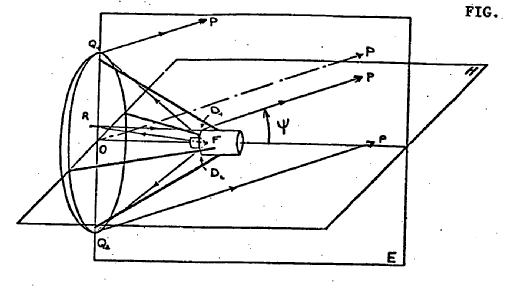
This place covers:
Changing the shape of (sub) reflectors that are responsible for backscattered energy that causes VSWR degradation.
Illustrative example of subject-matter classified in this group:
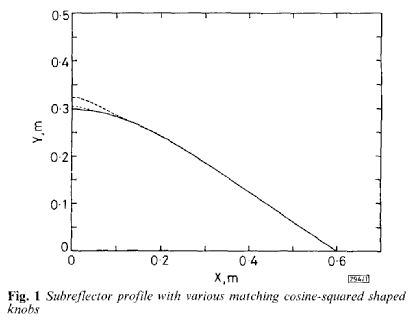
This place covers:
Changing the aperture illumination used for generating the secondary pattern.
In the transmit mode of a reflector antenna, the power from the feed that is not intercepted by the reflecting elements.
Illustrative example of subject-matter classified in this group:
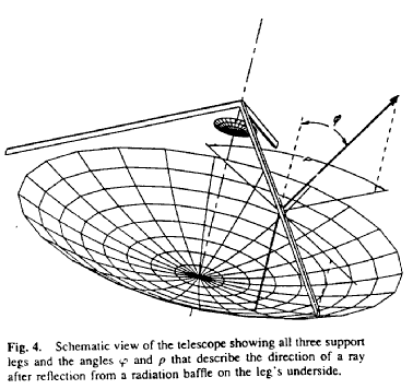
This place covers:
A condition resulting from objects lying in the path of rays arriving at or departing from the aperture of an antenna.
The shadowing causes increase in sidelobe levels.
Illustrative example of subject-matter classified in this group:
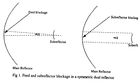
This place does not cover:
offset feeding |
This place covers:
The polarisation orthogonal to a reference polarisation, that is co-polarisation; polarisation purity; cross-polarisation suppression.
Illustrative examples of subject-matter classified in this group:
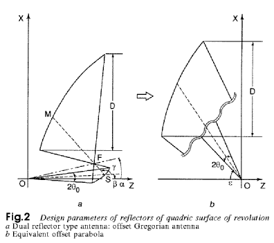
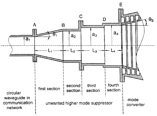
This place covers:
Mechanical details thereof.
Illustrative example of subject-matter classified in this group:
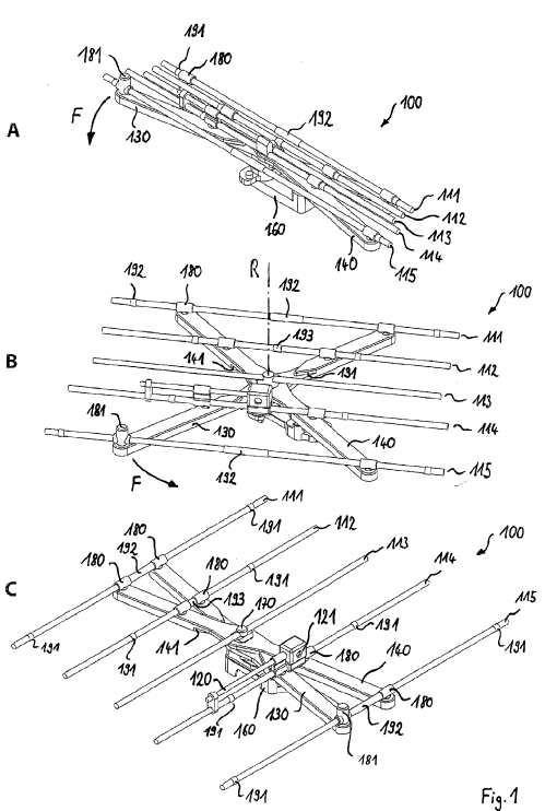
This place covers:
Lens antenna. An antenna consisting of an electromagnetic lens and a feed that illuminates it.
Illustrative example of subject-matter classified in this group:
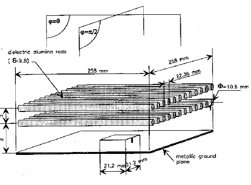
This place does not cover:
using refracting or diffracting devices, e.g. lens |
This place covers:
For transforming an incident wavefront into another wavefront, e.g. spherical into plane.
Illustrative examples of subject-matter classified in this group:
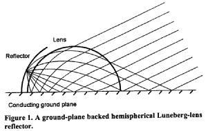
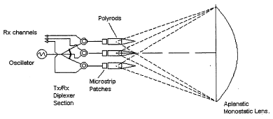
This place covers:
Fresnel lens antenna. An antenna consisting of a feed and a lens, usually planar, that transmits the radiated power from the feed through the central zone and alternate Fresnel zones of the illuminating field on the lens.
Illustrative example of subject-matter classified in this group:
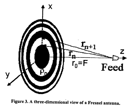
Planar lens antenna; Fresnel zone plate antenna (FZP, FZPA).
This place covers:
Quasi-optical wave of generating an antenna beam, based on constructive interference. Operates as kind of grating.
Illustrative example of subject-matter classified in this group:
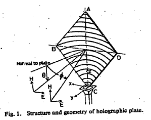
This place covers:
For example: dielectrically filled horns.
Illustrative example of subject-matter classified in this group:
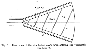
This place does not cover:
corrugated horns | |
producing a circular polarisation |
This place covers:
Coated/embedded monopole.
Illustrative examples of subject-matter classified in this group:
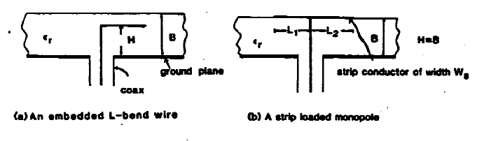
This place covers:
An antenna consisting of one or more reflecting surfaces and a radiating (receiving) feed system.
Reflector antenna, dish antenna.
This place covers:
A reflector formed by rotating s segment of plane curve about a nonintersecting coplanar line.
Example: torus antenna.
Illustrative example of subject-matter classified in this group:
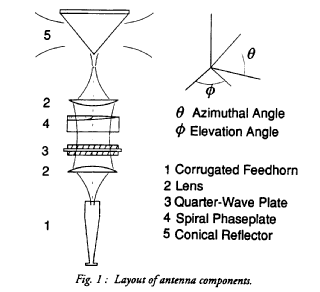
This place does not cover:
biconical horns |
This place covers:
An antenna consisting of a very directive feed located close to ground level and oriented so that its beam illuminates an elevated reflector that is oriented so as to produce a horizontal beam.
Illustrative example of subject-matter classified in this group:
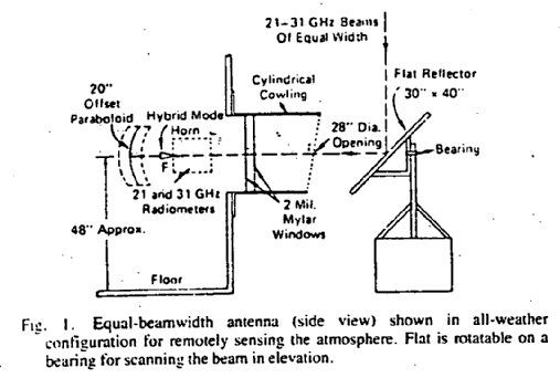
This place does not cover:
periscopic fed Cassegrain antennas | |
passive relays |
This place covers:
Corner reflector antenna, that is an antenna consisting of a feed and a corner reflector.
Illustrative example of subject-matter classified in this group:
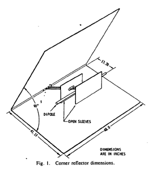
This place covers:
Any dipole with any planar reflecting surface.
Illustrative example of subject-matter classified in this group:
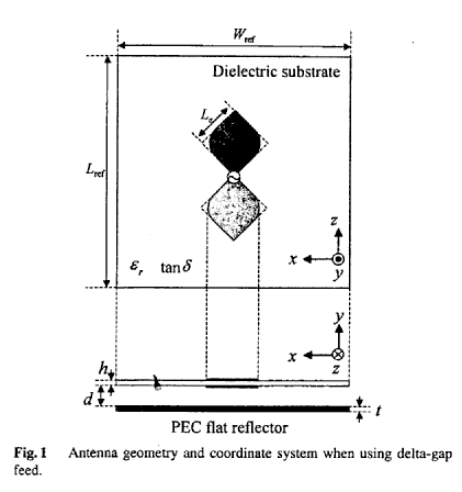
This place does not cover:
takes precedence; strip line | |
Combination of a dipole with a plane reflecting surface |
This place covers:
A feed with a dish.
Illustrative example of subject-matter classified in this group:
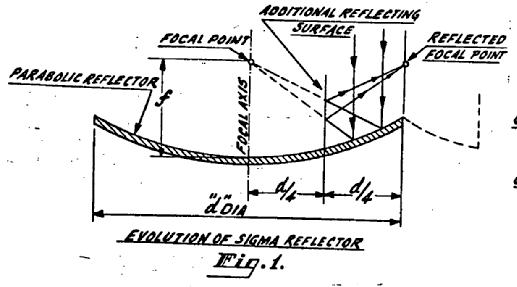
This place does not cover:
wherein the surfaces are concave |
In patent documents the following words are often used:
Parabolic, paraboloidal, paraboloid.
This place covers:
Illustrative example of subject-matter classified in this group:
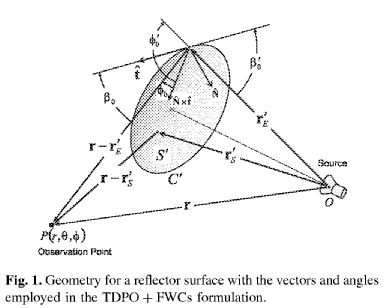
This place does not cover:
the primary radiating source being a single radiating element, e.g. a dipole, a slot, a waveguide termination |
In patent documents the following words are often used:
Prime focus feed; center-feed, centre-fed; front feed; front-fed.
This place covers:
An antenna consisting of a portion of a paraboloidal reflector fed with an offset horn that physically intersects the reflector, part of the wall of the horn being removed to form the antenna aperture.
The horn is usually either pyramidal or conical, with an axis perpendicular to that of the paraboloid.
Advantage: aperture blockage by the feed is reduced.
Illustrative example of subject-matter classified in this group:
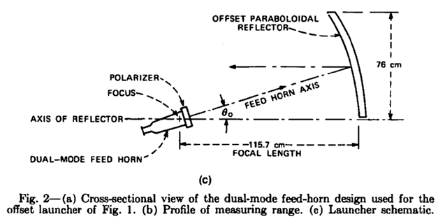
This place covers:
Splash plate feeds can have various profiles, optimised for VSWR.
Illustrative example of subject-matter classified in this group:
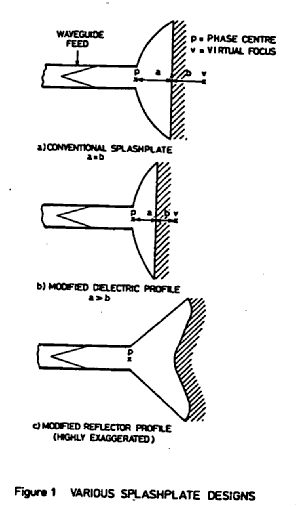
This place covers:
Should be interpreted as dual-polarised.
Illustrative example of subject-matter classified in this group:
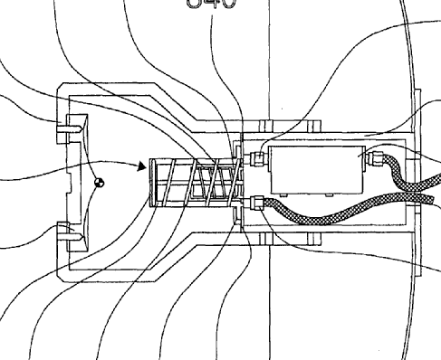
This place covers:
Cheese: a reflector antenna having a cylindrical reflector enclosed by two parallel conducting plates perpendicular to the cylinder, spaced more than one wavelength apart.
Contrast with Pillbox: a reflector antenna having a cylindrical reflector enclosed by two parallel conducting plates perpendicular to the cylinder, spaced less than one wavelength apart.
Illustrative example of subject-matter classified in this group:
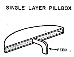
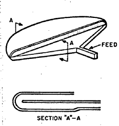
This place covers:
A continuous distribution of sources of electromagnetic radiation, lying along a line segment.
Illustrative example of subject-matter classified in this group:
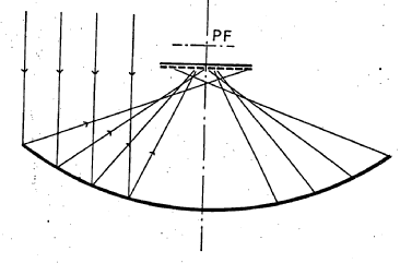
This place covers:
Reflector fed by a number of antenna elements.
Illustrative example of subject-matter classified in this group:
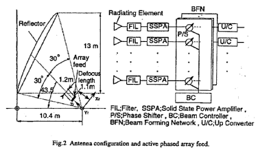
This place does not cover:
the primary radiating source comprising two or more radiating elements |
In patent documents, the following words/expressions are often used as synonyms:
- "array-fed", "array feed", "feed array", "feed cluster", "multifeed reflector" and "duofeed"
This place covers:
Cylindrical reflector (curved in one dimension) illuminated by a line source of finite extent.
Illustrative example of subject-matter classified in this group:
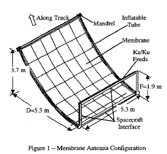
This place covers:
Illustrative example of subject-matter classified in this group:
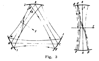
This place does not cover:
producing pencil beam by two cylindrical reflectors with their focal lines orthogonally disposed |
Attention is drawn to the following places, which may be of interest for search:
surfaces of convex toroidal shape | |
using a deflecting plane mirror | |
splash plate feeds |
This place covers:
Illustrative example of subject-matter classified in this group:
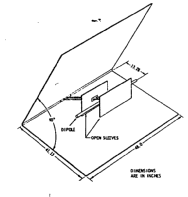
Inactive.
This place covers:
Classical dual reflector systems.
Cassegrain reflector antenna with a convex subreflector; Gregorian reflector antenna with a concave subreflector.
Illustrative example of subject-matter classified in this group:
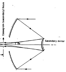
This place covers:
Quasi-optical collimators.
Illustrative example of subject-matter classified in this group:
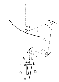
This place covers:
Dual-offset Cassegrain or Gregorian systems.
Illustrative example of subject-matter classified in this group:
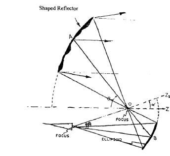
This place covers:
The sub-reflector is connected to the feeder system; mechanical considerations.
Illustrative example of subject-matter classified in this group:
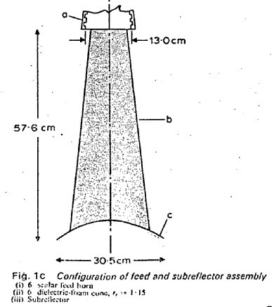
This place does not cover:
with feed supported subreflector (splash plate feeds) |
This place covers:
For example: polarisation sensitive main reflector in a twist reflector system.
Illustrative example of subject-matter classified in this group:
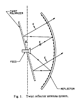
This place covers:
An antenna whose radiation pattern consists of a single main lobe with narrow principal half-power beamwidths and sidelobes having relatively low levels.
Illustrative example of subject-matter classified in this group:
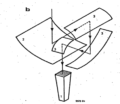
This place covers:
It is either a reflector or a director.
Illustrative example of subject-matter classified in this group:
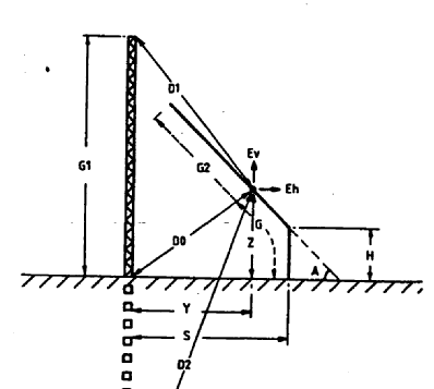
Group is inactive.
This place covers:
Illustrative example of subject-matter classified in this group:
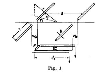
This place covers:
Monopole with either a reflector or a director in the form of a monopole.
Illustrative example of subject-matter classified in this group:
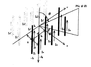
Group is inactive.
This place covers:
This is inherently a yagi-principle: the parasitic elements should have a similar shape as the excited element.
Illustrative example of subject-matter classified in this group:
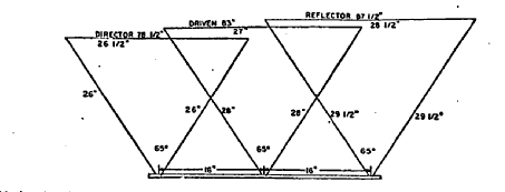
This place does not cover:
using a secondary device in the form of two or more substantially straight conductive elements (log-periodic aerials) | |
constituting a reflecting surface |
This place covers:
A linear end-fire array consisting of a driven element, a reflector element, and one or more director elements.
Illustrative example of subject-matter classified in this group:
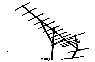
In this place, the following terms or expressions are used with the meaning indicated:
Driven element | radiating element coupled directly to the feed line of an antenna |
Director element | a parasitic element located forward of the driven element |
Reflector element | a parasitic element located in a direction other than forward. |
In patent documents, the following words/expressions are often used as synonyms:
- "Yagi-antenna" and "Yagi-Uda antenna"
This place covers:
For example monopole yagis and ESPAR.
Illustrative examples of subject-matter classified in this group:
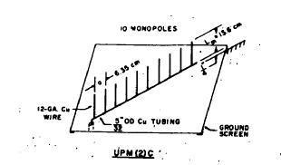
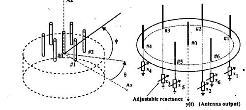
This place covers:
An antenna comprised of a number of identical radiating elements in a regular arrangement and excited to obtain a prescribed radiation pattern.
This place does not cover:
Producing a beam the orientation or the shape of the directional pattern of which can be changed or varied |
Attention is drawn to the following places, which may be of interest for search:
Combination of imbricated antennas or arrays operating on different wavebands | |
Electrically-long antennas |
In patent documents, the following words/expressions are often used as synonyms:
array antenna | antenna array |
This place covers:
Sub-arrays: In large arrays, the elements may be divided into a plurality of subarrays. The division into sub-arrays have a number of advantages, e.g. reduced number of phase shifters, but a more complex feed layout.
This place covers:
The power is distributed using a radial waveguide.
Illustrative example of subject-matter classified in this group:
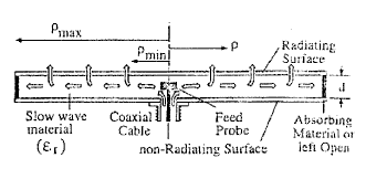
In this place, the following terms or expressions are used with the meaning indicated:
RLSA | Radial line Slot Antenna |
This place covers:
The power is distributed via space to receiving elements, which in turn (re)transmit: e.g. active lens, see also H01Q 3/46.
Illustrative examples of subject-matter classified in this group:
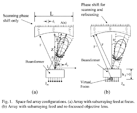
This place covers:
Any T/R module is classified here; the modules can be arrays themselves, e.g. subarrays.
Illustrative example of subject-matter classified in this group:
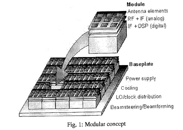
Attention is drawn to the following places, which may be of interest for search:
Constructional details for solid-state radar subsystems | |
By semiconductor devices | |
Transmit/receive switching |
This place covers:
The power is distributed using a parallel plate waveguide.
Illustrative example of subject-matter classified in this group:
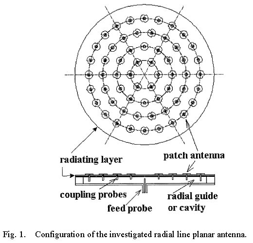
This place does not cover:
multibeam arrays |
This place covers:
The power is distributed using a linear waveguide of a particular cross-section.
Illustrative example of subject-matter classified in this group:
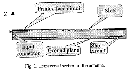
Travelling wave feed.
This place covers:
The distributing waveguide contains slots.
Illustrative example of subject-matter classified in this group:
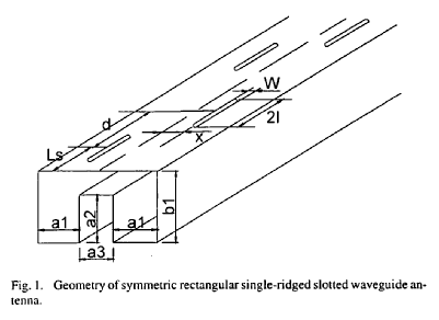
This place does not cover:
combination with horns |
This place covers:
Multiple waveguide are formed into an array.
Illustrative example of subject-matter classified in this group:
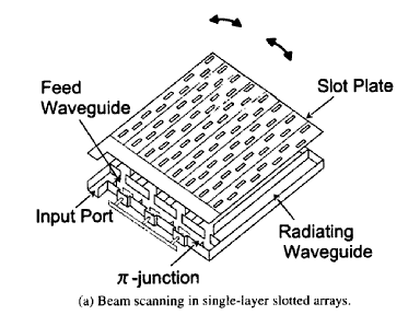
This place covers:
The individual arrays are disposed on a cone or a cylinder.
Illustrative example of subject-matter classified in this group:
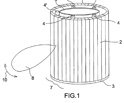
This place covers:
Illustrative example of subject-matter classified in this group:
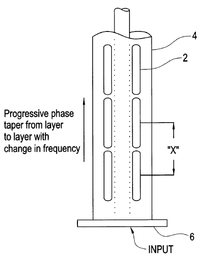
Inactive.
This place covers:
Power distribution by linear dielectric waveguide.
Illustrative example of subject-matter classified in this group:
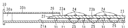
This place covers:
Power distribution using stripline, includes microstrips, suspended stripline, etc.
Illustrative example of subject-matter classified in this group:
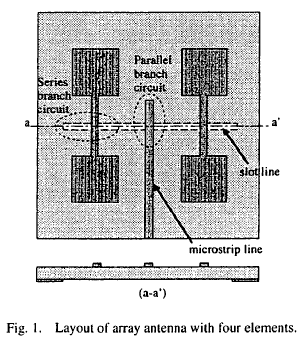
This place does not cover:
Stripline fed arrays |
This place covers:
Here suspended stripline.
The ground plane is not connected directly on the substrate but separated by air space.
Illustrative example of subject-matter classified in this group:
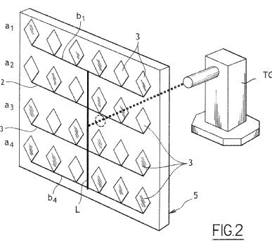
This place covers:
Tile construction: the radiating elements, active devices are in parallel layers, which is also the direction in which the array is made.
Brick construction: the interconnections are straightforward / perpendicular to the plane of the array.
Illustrative example of subject-matter classified in this group:
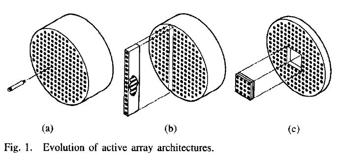
(a) isolated T/R modules, (b) brick architecture, (c) tile architecture.
This place does not cover:
manufacturing waveguides |
In this place, the following terms or expressions are used with the meaning indicated:
Flip chip bonding method | metal bumps are formed on the surface of a chip, then the chip is faced down onto metal pads of a substrate/printed circuit board and by soldering/pressing/ thermosonic or ultrasonic bumps and pads are connected (see H01L 21/00, H01L 23/00, H01L 25/00 ) |
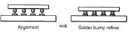
This place covers:
Using monolithic techniques to produce the array: upcoming technology ceramic cofiring technologies.
Illustrative example of subject-matter classified in this group:
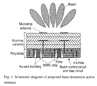
This place covers:
This class only specifies the array geometry, not how they are fed, or whether the array is a phased array
Attention is drawn to the following places, which may be of interest for search:
varying the relative phase or relative amplitude of energisation between two or more active radiating elements; varying the distribution of energy across a radiating aperture | H01Q 3/26 and subgroups |
This place covers:
Two-dimensional array.
Illustrative example of subject-matter classified in this group:
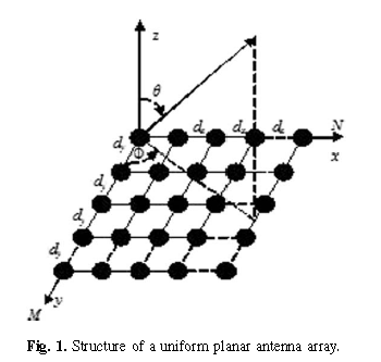
This place covers:
2D dipole array.
Illustrative example of subject-matter classified in this group:
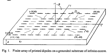
This place does not cover:
using dipole aerials |
This place covers:
2D slot/horn array, includes vivaldi elements.
Illustrative example of subject-matter classified in this group:
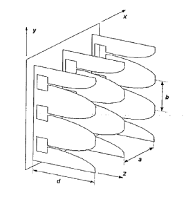
This place does not cover:
slotted waveguides arrays |
This place covers:
2D array of patches.
Illustrative example of subject-matter classified in this group:
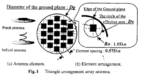
This place covers:
Specific end-fire type of elements, e.g. rod antennas, helical antennas.
Illustrative example of subject-matter classified in this group:
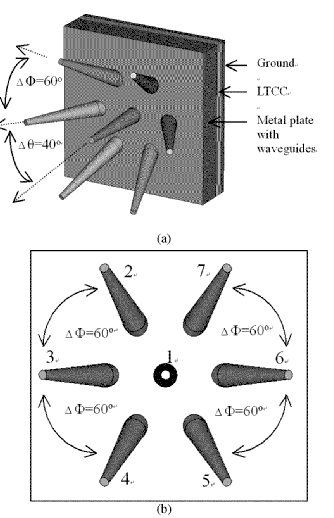
This place covers:
Arrays of travelling wave or leaky wave units.
Illustrative example of subject-matter classified in this group:
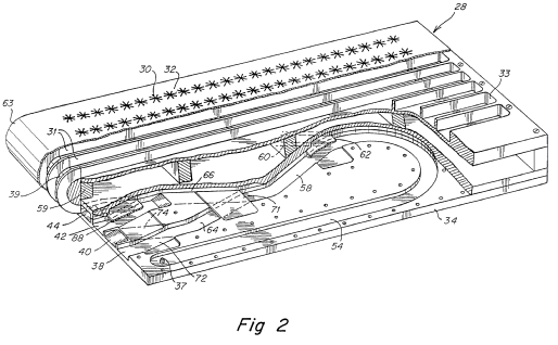
This place does not cover:
using parallel coplanar travelling wave or leaky wave aerial units |
This place covers:
A one-dimensional array of elements whose corresponding points lie along a straight line.
Illustrative example of subject-matter classified in this group:
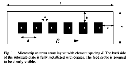
This place does not cover:
the units being spaced along or adjacent to a rectilinear path |
In patent documents, the following words/expressions are often used as synonyms:
- "linear array antenna" and "uniform linear array"
This place covers:
A linear array of radiating elements, usually dipoles, with their axis lying in a straight line.
Illustrative example of subject-matter classified in this group:
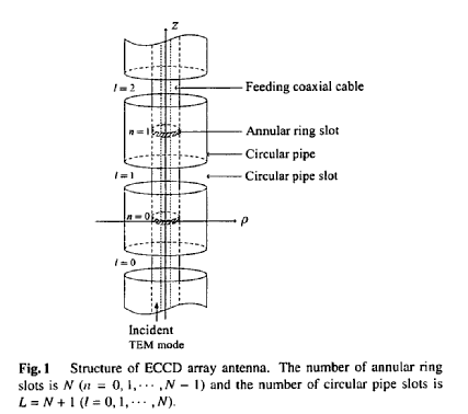
This place covers:
Illustrative example of subject-matter classified in this group:
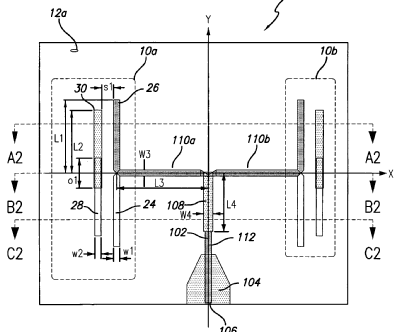
This place does not cover:
Non-resonant antennas, e.g. travelling-wave antennas | |
Travelling-wave antennas comprising transmission line loaded with transverse elements, e.g. "fishbone" antenna | |
Yagi antennas |
This place covers:
A pair of vertical antennas separated by a distance of one-half wavelength or less, and connected in phase opposition to produce a radiation pattern having the shape of the figure eight in all planes containing the centers of the two antennas.
Two vertical elements fed by 180° apart and mounted so that the system may be rotated; used for direction finding.
Illustrative example of subject-matter classified in this group:
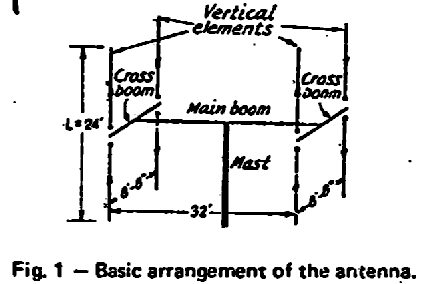
This place covers:
Illustrative example of subject-matter classified in this group:
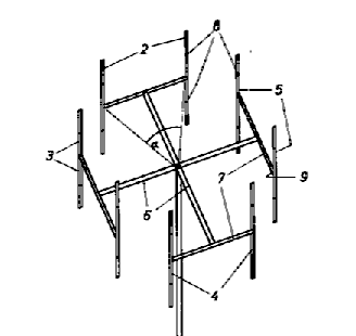
Inactive group.
This place covers:
An array of elements whose corresponding points lay on a circle, or a part thereof, e.g. an arc.
Illustrative example of subject-matter classified in this group:
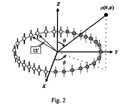
This place does not cover:
slotted waveguide arrays | |
circularly or helically slotted waveguides |
In patent documents, the following words/expressions are often used as synonyms:
- " ring arrays" circular arrays", "conical array", "cylindrical array" and "spherical array"
This place covers:
Radiating in all directions simultaneously.
Illustrative examples of subject-matter classified in this group:
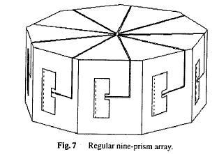
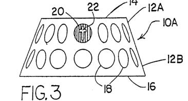
This place does not cover:
turnstile aerials |
This place covers:
An antenna that is designed to have a prescribed pattern shape differing significantly from the obtained from a uniform-phase aperture of the same size. not-equally or non-equally amplitude or phase; shaped-beam antenna.
Also arrays where the elements are not located in a regular arrangement but e.g. randomly or thinned ; not-equally spaced.
Space-tapered or density-tapered array, that is an array antenna whose radiation pattern is shaped by varying the density of driven radiating elements over the array surface.
Illustrative examples of subject-matter classified in this group:
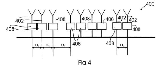
This place covers:
Zooming antennas, or near-field focusing antennas. Inactive group.
Illustrative examples of subject-matter classified in this group:
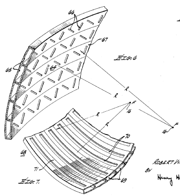
This place covers:
The ability to radiate different polarisations.
Illustrative examples of subject-matter classified in this group:
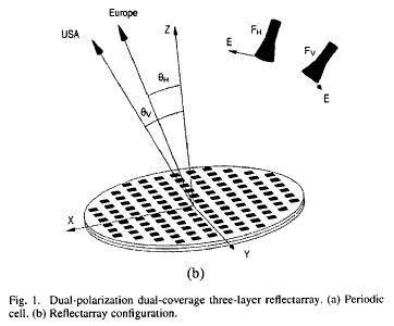
This place does not cover:
circularly polarised patch antennas | |
circularly polarised horns | |
cross-polarised horns | |
polarisation converters | |
cross-polarised rear feeds | |
crossed polarisation dual antenna |
This place covers:
Variable polarisation, adaptive polarisation.
Illustrative examples of subject-matter classified in this group:
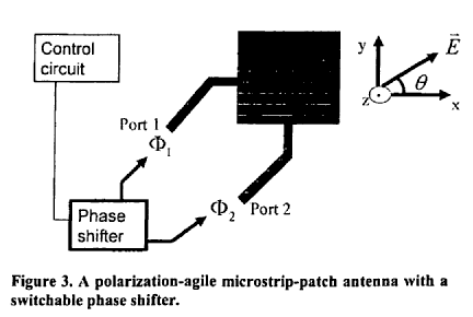
This place does not cover:
polarising devices | |
tracking by comparing linear polarisation compounds | |
reducing depolarisation effects | |
polarisation diversity |
This place covers:
An antenna composed of two dipole antennas, perpendicular to each other, with their axes intersecting at their midpoints. Usually, the currents on the two dipole antennas are equal and in phase quadrature.
Illustrative example of subject-matter classified in this group:
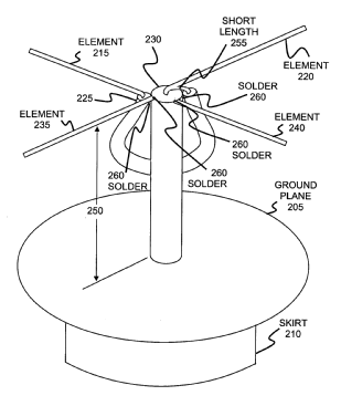
This place covers:
Multiple antennas or antenna arrays defining an antenna system, but not having any relationship except being defined as part of the antenna system.
Illustrative example of subject-matter classified in this group:
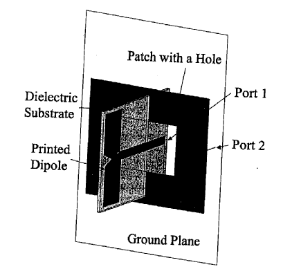
This place does not cover:
Combinations of substantially independent non-interacting aerial units or systems |
This place covers:
For example used for pattern synthesis; this class is NOT used for diversity applications (H04B 7/08 and subgroups).
If the antennas defining the system do not operate on the same frequency, this group does not apply.
Illustrative example of subject-matter classified in this group:
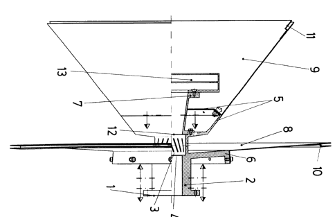
This place does not cover:
Antennas or antenna systems providing at least two radiating patterns |
This place covers:
One of the constituents is an array.
Illustrative example of subject-matter classified in this group:
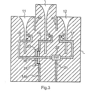
This place does not cover:
one unit or more being an array of identical aerial elements |
This place covers:
Form of a signal processing antenna system having circuit elements associated with its radiating element(s) that perform functions such as multiplication, storage, correlation, and time modulation of the input signals
Data processing is used for achieving the final pattern.
Illustrative example of subject-matter classified in this group:
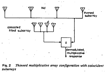
This place covers:
Separate antennas operating at different frequencies sharing a feeder system (or feed point). This leads to isolation problems.
Illustrative examples of subject-matter classified in this group:
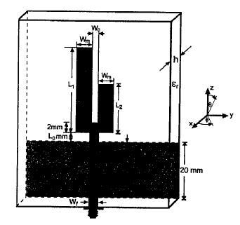
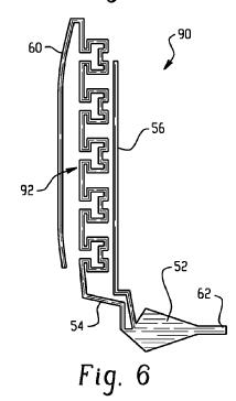
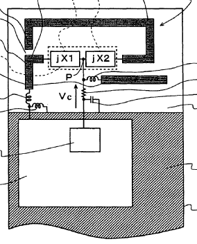
This place covers:
Only used in conjunction with another class, and to emphasize there is active circuitry integrated, or mounted at the antenna, e.g. amplifiers, mixers, etc. Not used on its own.
This place covers:
An antenna capable of creating a family of major lobes from a single non-moving aperture, through use of a multiport feed, with one-to-one correspondence between input ports and member lobes, the latter characterized by having unique main beam pointing directions.
Often, the multiple main beam angular positions are arranged to provide complete coverage of a solid angle region of space.
Illustrative example of subject-matter classified in this group:
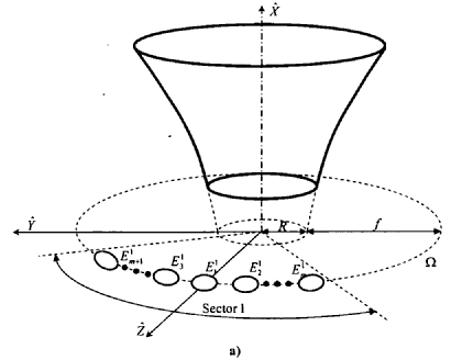
This place does not cover:
Arrangements for changing or varying the orientation or the shape of the directional pattern |
This place covers:
Illustrative example of subject-matter classified in this group:
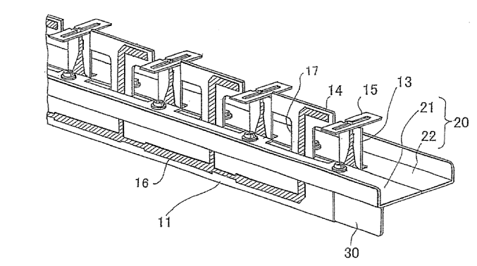
This place does not cover:
orthomode horns | |
cross-polarised rear feeds | |
orthomode transducers |
This place covers:
Illustrative example of subject-matter classified in this group:
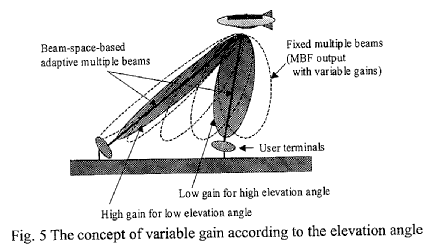
This place covers:
Illustrative example of subject-matter classified in this group:
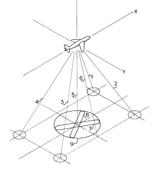
This place covers:
Illustrative example of subject-matter classified in this group:
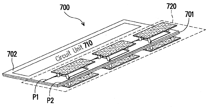
This place does not cover:
providing two patterns of opposite direction; back to back antennas |
This place covers:
Illustrative example of subject-matter classified in this group:
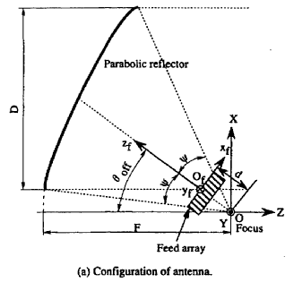
This place does not cover:
for operation on different wavebands |
This place covers:
Illustrative example of subject-matter classified in this group:
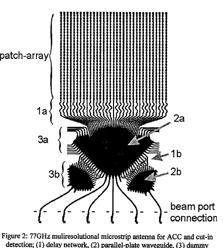
This place covers:
Sum pattern: a radiation pattern characterized by a single main lobe whose cross section is essentially elliptical, and a family of side lobes the latter usually at a relatively low level.
Difference pattern: a radiation pattern characterized by a pair of main lobes of opposite phase, separated by a single null, plus a family of side lobes, the latter usually desired to be at a low level.
Antennas used in many radar applications are capable of producing a sum pattern and two orthogonal difference patterns, the difference pattern can be employed to determine the position of a target in a rightlleft and up/down sense by the antenna pointing, which places the target in the null between the twin lobes of each difference pattern.
Radar system is called monopulse radar system because direction-finding information is obtainable from a single pulse A monopulse receiving system includes a monopulse circuit which receives signals from the antenna and forms sum and difference monopulse output signals. The sum and difference signals are formed by combining received antenna signals in a particular manner. The signals can be combined using circuits referred to as hybrid circuits. The monopulse sum and difference signals can be formed either at the transmitted signal frequency or, after down conversion of a return signal, at a lower frequency.
Illustrative example of subject-matter classified in this group:
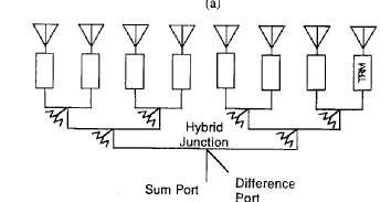
This place does not cover:
multimode aerials |
This place covers:
Illustrative examples of subject-matter classified in this group:
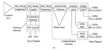
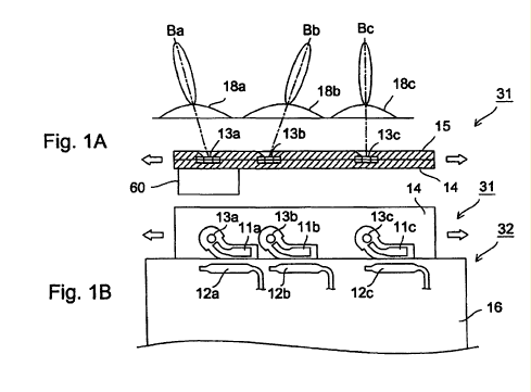
This place does not cover:
corrugated horns |