CPC Definition - Subclass G02B
This place covers:
Passive optical elements and systems, i.e. elements and systems which are not based on the optical properties of the material used being altered by the application of an external field.
In particular:
- Optical elements characterised by the material of which they are made
- Simple or compound lenses
- Optical elements other than lenses (e.g. prisms, diffusers, mirrors, diffraction gratings, filters, polarisers)
- Light guides; Structural details of arrangements comprising light guides and other optical elements, e.g. couplings (Note: to be dealt with in a further FCR document relating to G02B 6/00)
- Mountings, adjusting means, or light-tight connections, for optical elements
- Optical objectives or lens systems characterised both by the number of the optical components and their arrangements according to their sign, i.e. + or -
- Optical objectives specially designed for specific purposes
- Optical objectives with means for varying the magnification, e.g. zoom lenses
- Systems with reflecting surfaces, with or without refracting elements, i.e. catadioptric or catoptric systems
- Optical condensers
- Microscopes
- Telescopes, e.g. binoculars; Periscopes; Instruments for viewing the inside of hollow bodies
- Eyepieces (e.g. for telescopes, microscopes); Magnifying glasses
- Optical devices or arrangements using movable or deformable optical elements
Examples of places where the subject matter of this place is covered when specially adapted, used for a particular purpose, or incorporated in a larger system:
Medical endoscopes | |
Surgical microscopes | |
Optical elements specially adapted for use in lighting devices or systems thereof | |
Refractors for light sources | |
Reflectors for light sources | |
Filters for light sources | |
Optical rangefinders | |
Spectacles | |
Apparatus or arrangements for taking photographs or for projecting or viewing them | |
Optical elements structurally combined with electric discharge tubes | |
Optics integrated in LED packages | |
Optics of laser cavities | |
Combination of optical elements with television receivers | |
Optical systems or arrangements in colour television systems | |
Heating arrangement for transparent or reflecting areas |
Attention is drawn to the following places, which may be of interest for search:
Hand, pocket, or shaving mirrors | |
Household mirrors | |
Apparatus for testing the eyes | |
Treatment for or protection of the eyes, e.g. protective goggles | |
Optical toys | |
Applying liquid films, e.g. spin coating | |
Working by laser beam, e.g. welding, cutting or boring | |
Grinding or polishing lenses or gratings | |
Producing optical elements from plastics | |
Layered products | |
Printing using a scanning light deflector | |
Diffractive or holographic structures on credit cards | |
Vehicle mirrors, e.g. rear-view or side-view | |
Optical micromechanical [MEMS] devices | |
Pressing lenses from molten glass | |
Surface treatment of glass by coating | |
Liquid crystals per se | |
Coating in general, e.g. CVD or sputtering | |
Supports, stands or frames in general | |
Solar heat collectors | |
Sighting devices for weapons | |
Interferometers | |
Measuring microscopes | |
Measuring distances; Surveying | |
Spectrometry | |
Testing of optical elements, systems or apparatus | |
Optical benches | |
Investigating or analysing materials by the use of optical means | |
Scanning probe techniques, e.g. near field microscopy | |
Systems using reflection of light e.g. lidar | |
Liquid crystal displays [LCDs] | |
Photography | |
Projection screens | |
Photosensitive materials | |
Photolithography | |
Fourier/Laplace transform optics, correlation | |
Optics of barcode scanners | |
Laser printers | |
Record carriers with diffractive or holographic structures | |
Holograms on banknotes | |
Control arrangements or circuits for displays other than CRTs | |
Sound lenses | |
Recording or reproducing by optical means, e.g. optical disks | |
Adjusting position or attitude, e.g. level, of instruments | |
Casings; Housings; Cabinets; Supports etc. | |
X-ray optics, gamma ray optics | |
Electron and ion "optics" | |
X-ray "optics" | |
Plasma display panels | |
Optical arrangements associated with CRTs, e.g. AR means | |
Electron or particle beam optics, e.g. electron microscopes | |
Light concentrating means for solar cells | |
Optics of microwaves or millimetre waves | |
Wavelength division multiplexing [WDM] systems | |
Facsimile transmission | |
Projection TV | |
Colour projection TV | |
Stereoscopic TV | |
TV cameras | |
Heating arrangements specially adapted for transparent or reflecting areas | |
X-ray technique | |
Electroluminescent OLED displays |
In this subclass, classification of additional information is mandatory,
For example, a document describing the detailed structure of a wire-grid polarizer should be classified with G02B 5/3058 INV – invention-information aspect of a wire-grid polarizer.
Instead a document describing a display system making explicit use of a wire-grid polarizer, without providing structural details of the polarizer itself, should be classified with G02B 5/3058 ADD – as to the additional-information aspect of a wire-grid polarizer.
In this place, the following terms or expressions are used with the meaning indicated:
Optical, Optics | Applies not only to visible light but also to ultraviolet or infrared radiation. |
Active optics | Optics based on the optical properties of a material used being altered by the application of external energy, e.g. electrical, magnetic, thermal or optical energy. |
Passive optics | Optics in which the optical properties of a material used are not altered by the application of external energy; external forces may act, however, to alter the shape, position or orientation of an optical element used. |
Catoptric | Optical systems involving reflective surfaces only. |
Catadioptric | Optical systems involving reflective and refractive surfaces. |
Simple lens or prism | Single lens or prism; simple lens, simple lenses, simple prism; simple prisms, simple. |
Compound lens or prism,Compound lens, Compound lenses, Compound prism, Compound prisms | Optical member the constituents of which are either close together without air-space or in broken contact; see also the Note after group G02B 13/00. |
Light | Applies to electromagnetic radiation, not only in the portion of the electromagnetic spectrum which can be perceived by the human eye (i.e. visible), but also to ultraviolet or infrared radiation. |
Objective | Lens or optical system designed to produce a real image of a real object. |
Eyepiece | Lens or optical system designed to produce a virtual image for viewing by the eye or by another optical system. |
Front, Rear | Is determined by looking from the more distant conjugate. |
In broken contact | Such that the air-space between the constituents of an optical member has no optical influence. |
In patent documents, the following abbreviations are often used:
LCD | Liquid Crystal Display |
MEMS | Microelectromechanical System |
DMD | Digital Micromirror Device |
This place covers:
Optical elements characterised by the material of which they are made.
Attention is drawn to the following places, which may be of interest for search:
Composition of optical glasses | |
Cements for glass |
In patent documents, the following abbreviations are often used:
CVD | Chemical Vapour Deposition |
PVD | Physical Vapour Deposition |
Attention is drawn to the following places, which may be of interest for search:
Reflection coatings | |
Coating of glass in general |
Attention is drawn to the following places, which may be of interest for search:
Surface plasmon devices | |
Anti-glare structures |
Attention is drawn to the following places, which may be of interest for search:
Surface treatment of glass by irradiation |
This place covers:
Simple or compound lenses including arrays.
Examples of places where the subject matter of this place is covered when specially adapted, used for a particular purpose, or incorporated in a larger system:
Ophthalmic lenses |
Attention is drawn to the following places, which may be of interest for search:
Artificial eyes | |
Watch or clock glasses |
This place covers:
Optical elements other than lenses, e.g. prisms, diffusers, mirrors, diffraction gratings, filters, polarisers,light absorbing elements, diaphragms, surface plasmon devices or birefringent or phase retarding elements
Filters for plasma panel displays are classified under H01J and in H01J 2217/49292. A further classification in G02B 5/20 is optional.
In this place, the following terms or expressions are used with the meaning indicated:
Mirror | device for which the essential characteristic is maximum reflectivity over a given spectral range. A reflecting layer in a mirror is defined as a layer adapted to play a role in the reflection of light, and thus it does not refer to other layers having essentially no reflective function, e.g. protective layers |
Filter | device for which the essential characteristic is spectral selectivity, i.e. not only the spectral range passed (for example, by transmission, reflection) but also the spectral range rejected (for example, by absorption, transmission, reflection) |
In patent documents, the following abbreviations are often used:
FSS | frequency selective surface |
This place does not cover:
Polarising elements |
Examples of places where the subject matter of this place is covered when specially adapted, used for a particular purpose, or incorporated in a larger system:
Filters specially adapted for photographic purposes |
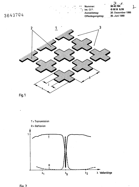
This place covers:
Filters in which the spectral filtering is performed by a conductive grid or mesh. The background is that for microwave optics, there has long existed a technique in which a conductive periodic pattern (a so-called "frequency selective surface" or FSS) is used to select a particular set of frequencies. For microwaves they are found in the subgroup H01Q 15/0006. In recent years this technique has been extended to IR and even visible wavelengths. It is these types of filters (and only these) which should go into G02B 5/204. Basically they look something like this:
This place does not cover:
Frequency filtering for aerials |
G02B 5/204 is not to be used for classifying normal spectral filters which just happen to have some additional conducting elements for other purposes not to do with spectral selection. In particular it is not for filters having a conductive EM shielding layer or a conductive louvre light blocking grid attached. For such arrangements, the following places may be appropriate:
- G02B 2207/121 - Antistatic or EM shielding layer
- G02B 2207/123 - Optical louvre elements, e.g. for directional light blocking
- G02B 1/116 - Multilayer inorganic AR coatings having a conducting layer light F21V
Examples of places where the subject matter of this place is covered when specially adapted, used for a particular purpose, or incorporated in a larger system:
Scanning systems using holograms, e.g. holographic scanners |
Attention is drawn to the following places, which may be of interest for search:
Processes or apparatus for producing holograms |
In this place, the following terms or expressions are used with the meaning indicated:
HOE | Holographic optical element |
This place covers:
Light guides per se, coupling light guides and mechanical protection of light guides.
The term "light" as used in G02B 6/00 refers to visible, infrared and ultraviolet light only.
The group covers the optical and mechanical aspects of light guides and light guide coupling, including the coupling of light into, out of and between light guides, as well as positioning, holding and protecting the light guides. This includes optical cables and arrangements for handling optical cables. The group covers the manufacture of some light guides, in particular optical waveguides of the integrated circuit kind.
The group covers light guides for illumination.
"Active" optics, i.e. where the optical property of the light guide or of an optical element coupled to the light guide is altered by the application of an external field are classified in G02F. Backlights characterised by the light guides for liquid crystal display panels are classified in G02B 6/0001 - G02B 6/0096.
Light amplifying light guides are classified in H01S.
Systems for communication are classified in H04, in particular optical transmission systems in general are classified in H04B 10/00, optical multiplex systems are classified in H04J 14/00, H04J 14/05 and H04J 14/07 and optical switching systems are classified in H04Q 11/0001. Network and system aspects are classified in H04 and not in G02B 6/00. Light guide arrangements as components, modules or subsystems of communication systems are classified in G02B 6/00: "in the box" aspects are classified in G02B 6/00. For example modules based on light guides for coupling, splitting, mixing, switching and dispersion compensation are classified in G02B 6/00.
Examples of places where the subject matter of this place is covered when specially adapted, used for a particular purpose, or incorporated in a larger system:
Endoscopes using optical fibres for illumination | |
Endoscopes with light guides | |
Medical endoscopes | |
Surgical instruments | |
Devices for illuminating a surgical field | |
Sensing by attenuation | |
Measuring temperature using optical fibre gratings | |
Measuring force or strain using an optical fibre | |
Investigating or analysing materials |
Attention is drawn to the following places, which may be of interest for search:
Organic materials for light guides | |
Christmas trees | |
Manufacture of plastic optical fibres | |
Manufacture of glass optical fibres | |
Glass compositions for optical fibres | |
Process of coating of optical fibres | |
Surveying of bore holes | |
Variable effect lighting | |
Measuring vibrations or sonic waves | |
Testing of light guide systems | |
Indicating arrangements using optical fibre ends | |
Scanners with light guides for illumination |
Light guides occur in many areas of technology. To avoid unnecessary double classification, the implementation of light guides in optical systems and instruments for which specific entries exist elsewhere (for example in surgical instruments or for chemical sensing) are not generally given a secondary class in G02B 6/00. This applies particularly to systems and instruments where light guide use is well established. The brief mention of a light guide does not in itself justify classifying in G02B 6/00. Exceptionally, where an optical aspect of the light guide coupling of general interest is disclosed, such a secondary class may be given. A class in G02B 6/00 is always given where a passive light guide per se has been specially adapted.
The primary protective coating immediately surrounding the cladding of an optical fibre is considered to be a component of an optical fibre and is thus classified in the G02B 6/02 subgroup. Further layers around the optical fibre are considered to form optical cables and are thus classified in G02B 6/44 and subgroups. This definition is also used to decide on the subgroup to be used for classifying a coupling. For example a clamp for an optical fibre is classified in G02B 6/36 whereas a clamp for an optical cable is classified in G02B 6/4471.
Light guides for illumination | |
Optical fibres with or without a coating | |
Waveguides of the integrated circuit kind | |
Subwavelength diameter waveguides | |
Other waveguides | |
Optical cables |
The following arrangement is observed for the coupling aspects of the various types of light guides:
Coupling light guides for illumination | |
Coupling of optical fibres | |
Coupling waveguides of the integrated circuit kind | G02B 6/12 - G02B 6/14, G02B 6/26, G02B 6/30, G02B 6/34, G02B 6/3596, G02B 6/42, G02B 6/43 |
Coupling subwavelength diameter waveguides | |
Coupling of other waveguides | |
Coupling, installation and handling of optical cables | |
Storage of optical fibres |
Polarisation aspects
The following arrangement is observed in relation to polarisation aspects of light guides and light guide couplings
Polarisation maintaining optical fibres | |
Polarisation issues within light guides per se, including optical fibres and planar waveguides (not polarisation maintaining optical fibres) | |
Polarisation manipulation by planar waveguide coupling | |
Polarisation manipulation by optical fibre coupling | |
Polarisation manipulating elements between light guides and optoelectronic elements |
Wavelength selective aspects
The following arrangement is observed in relation to wavelength aspects of light guides and light guide couplings
Wavelength affecting properties of optical fibres (e.g. performance and mounting of single gratings or filters in optical fibre, dispersion tailoring) | G02B 6/02 - G02B 6/03694, especially G02B 6/02052 - G02B 6/02209 and G02B 6/02214 - G02B 6/02285 |
Wavelength selective elements (e.g. gratings, filters) in planar waveguides | G02B 6/122 - G02B 6/138, especially G02B 6/124, and G02B 6/12007 - G02B 6/12033 |
Coupling of planar waveguides for wavelength selection | |
Coupling of optical fibres for wavelength selection | |
Wavelength selective elements between light guides and optoelectronic elements |
Indexing Codes are used in some subgroups related particularly to coupling aspects to indicate additional details not available for the particular type of light guide, for example G02B 6/293 - G02B 6/29398 are assigned to waveguides of the integrated circuit kind with wavelength selective elements in addition to G02B 6/12007.
The Indexing Codes corresponding to G02B 6/0001 - G02B 6/001 and G02B 6/0096 are in F21V 2200/00.
Indexing Codes with additional detail compared to the subgroups exist in various parts of G02B 6/00, including G02B 6/032, G02B 6/02123, G02B 6/2804, G02B 6/36, G02B 6/4292 and G02B 6/4296.
G02B 2006/0098 is assigned to light guides for scanning in addition to the appropriate invention group which depends on the type of light guide.
An Indexing Code is occasionally given as a tag to the implementation of light guides in optical systems which are not covered by G02B 6/00 for assisting awareness of the existence of the related subclasses.
In this place, the following terms or expressions are used with the meaning indicated:
Planar waveguides | waveguides of the integrated circuit kind |
This place covers:
Aspects of the light guides for illumination per se as well as light coupling aspects.
Further details of subgroups
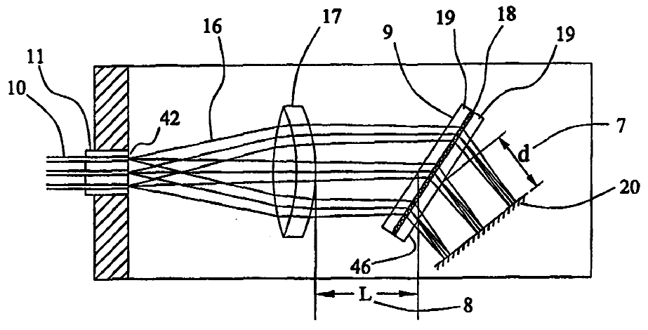
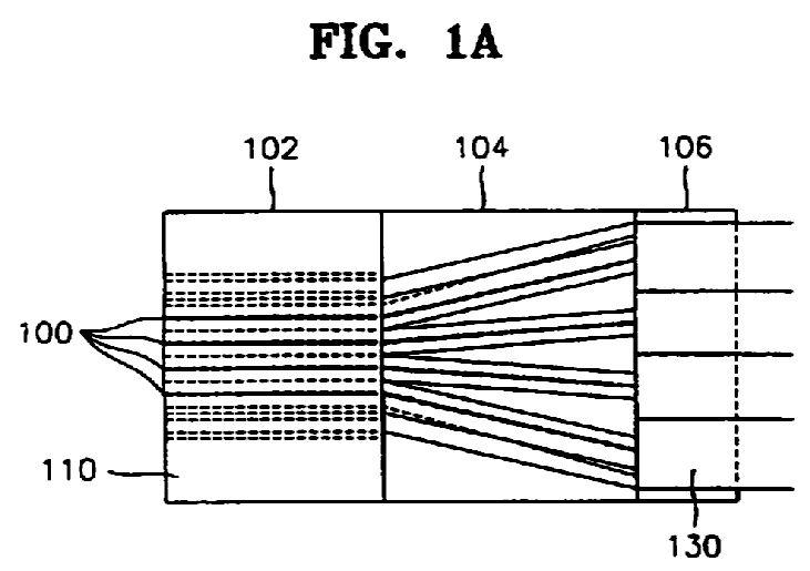
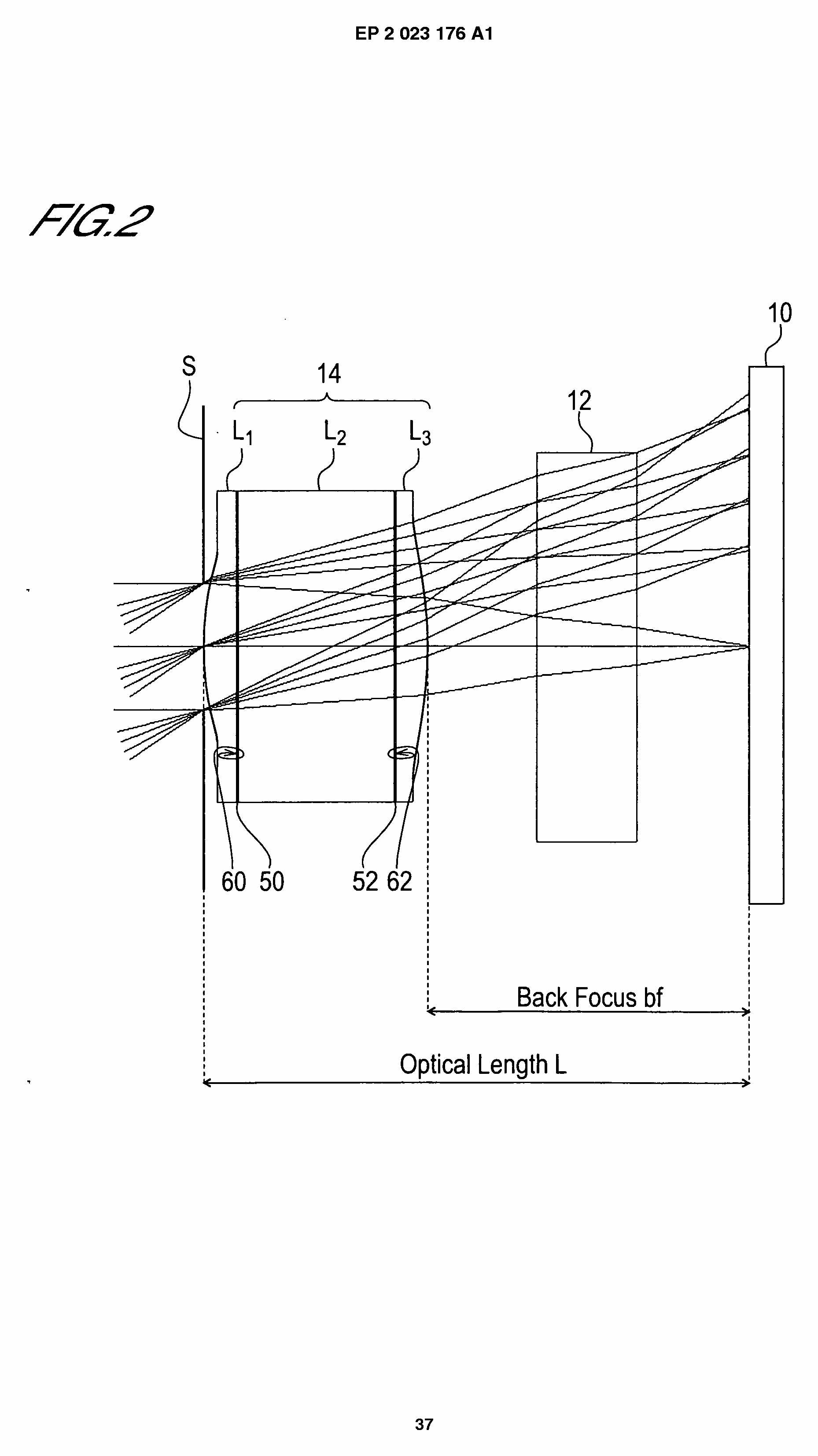
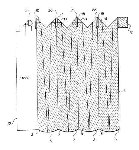
Illustrative example of the subject matter classified in this group:
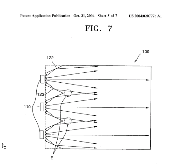
Grooves in the light input face of light guide 100. (Source US2004/0207775 A1).
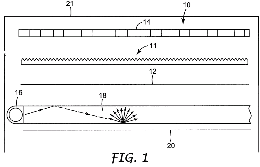
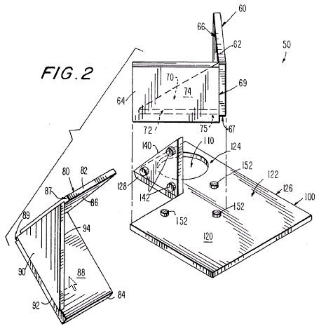
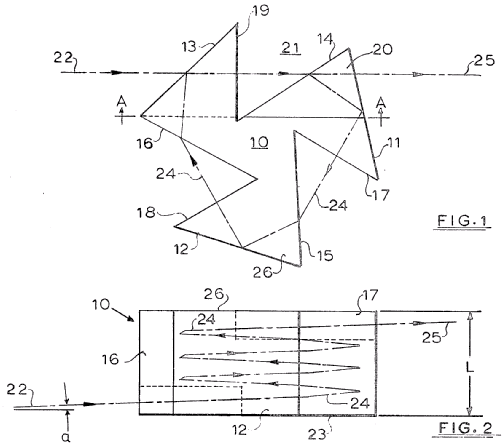
Illustrative example of the subject matter classified in this group:
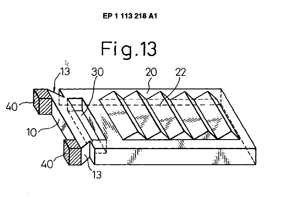
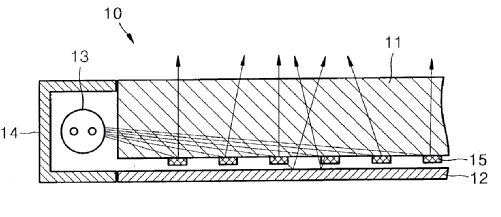
Redirecting reflective surfaces 13. (Source EP1113218 A1).
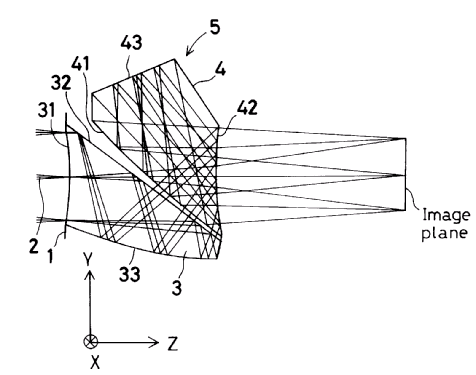
Illustrative example of the subject matter classified in this group:
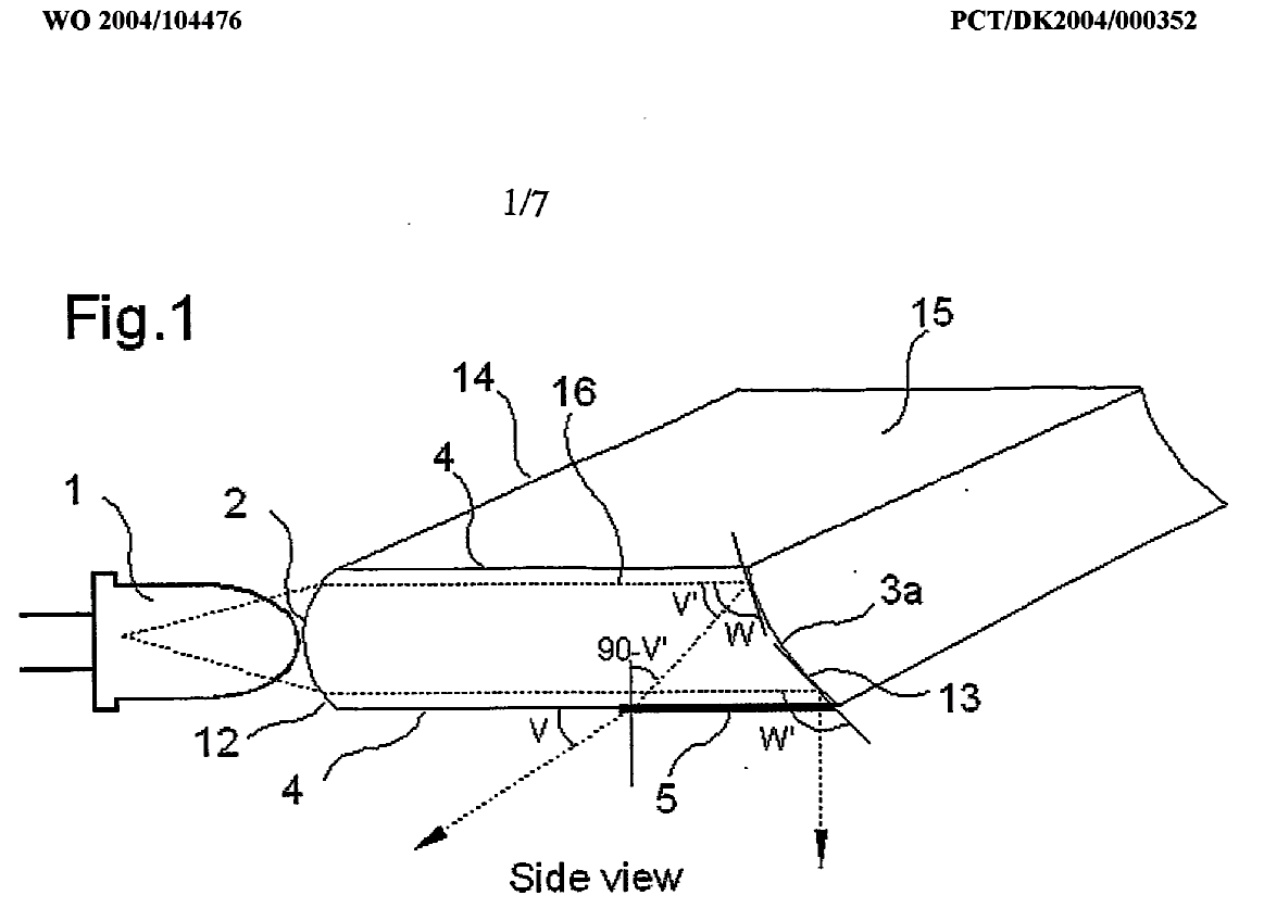
Input face 2 shaped as a lens surface. (Source WO 2004/104476).
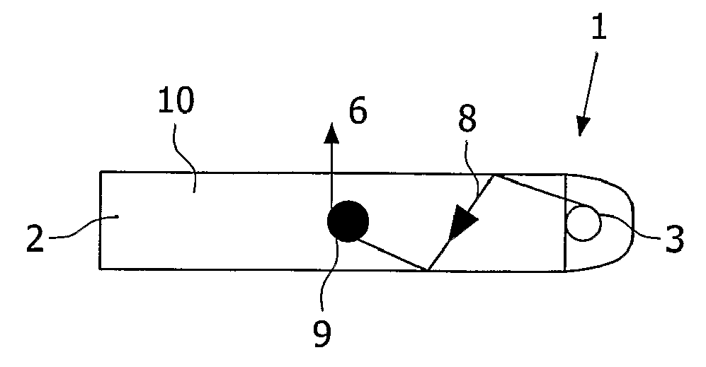
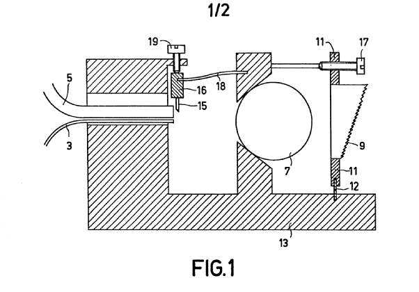
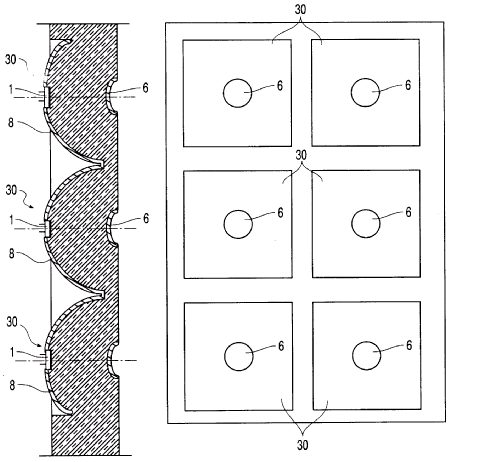
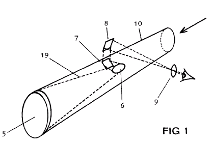
Illustrative example of the subject matter classified in this group:
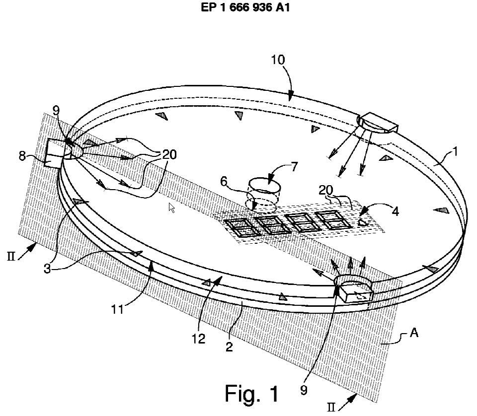
Recesses 9 in the light guide housing the light sources 8. (Source EP1666936 A1).
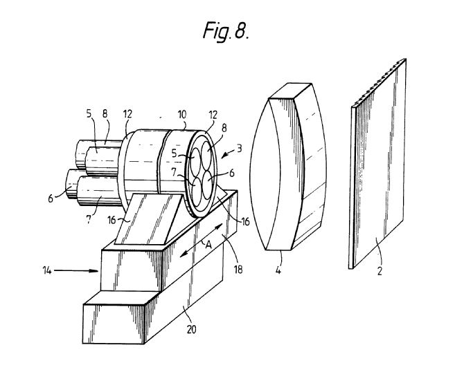
Illustrative example of the subject matter classified in this group:
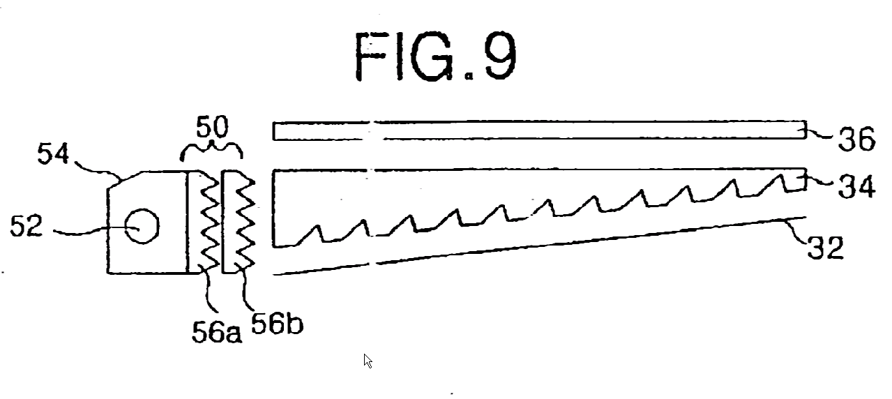
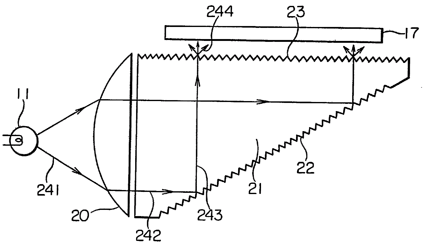
Prismatic sheets 56a, 56b between light source 52 and light guide 34. (Source US2003/0117793 A1).
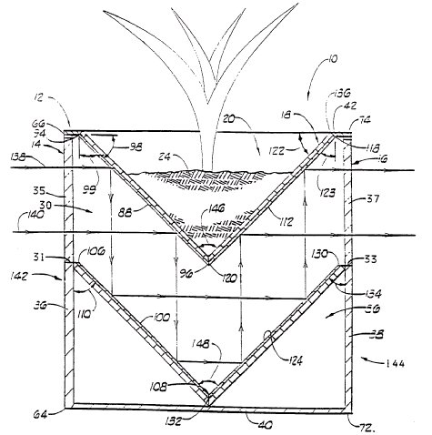
Illustrative example of the subject matter classified in this group:
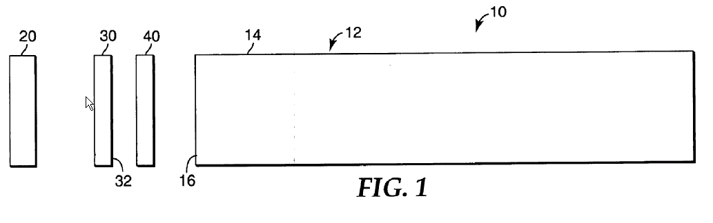
Interference reflector 30 as wavelength selective element between light source 20 and light guide 12. (Source US2006/0002678 A1).
Illustrative example of the subject matter classified in this group:
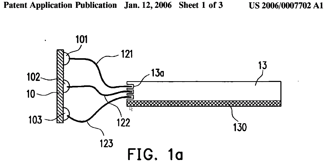 Intermediate light guides (optical fibers 121, 122, 123) for coupling into light guide plate 13. (source US2006/0007702 A1).
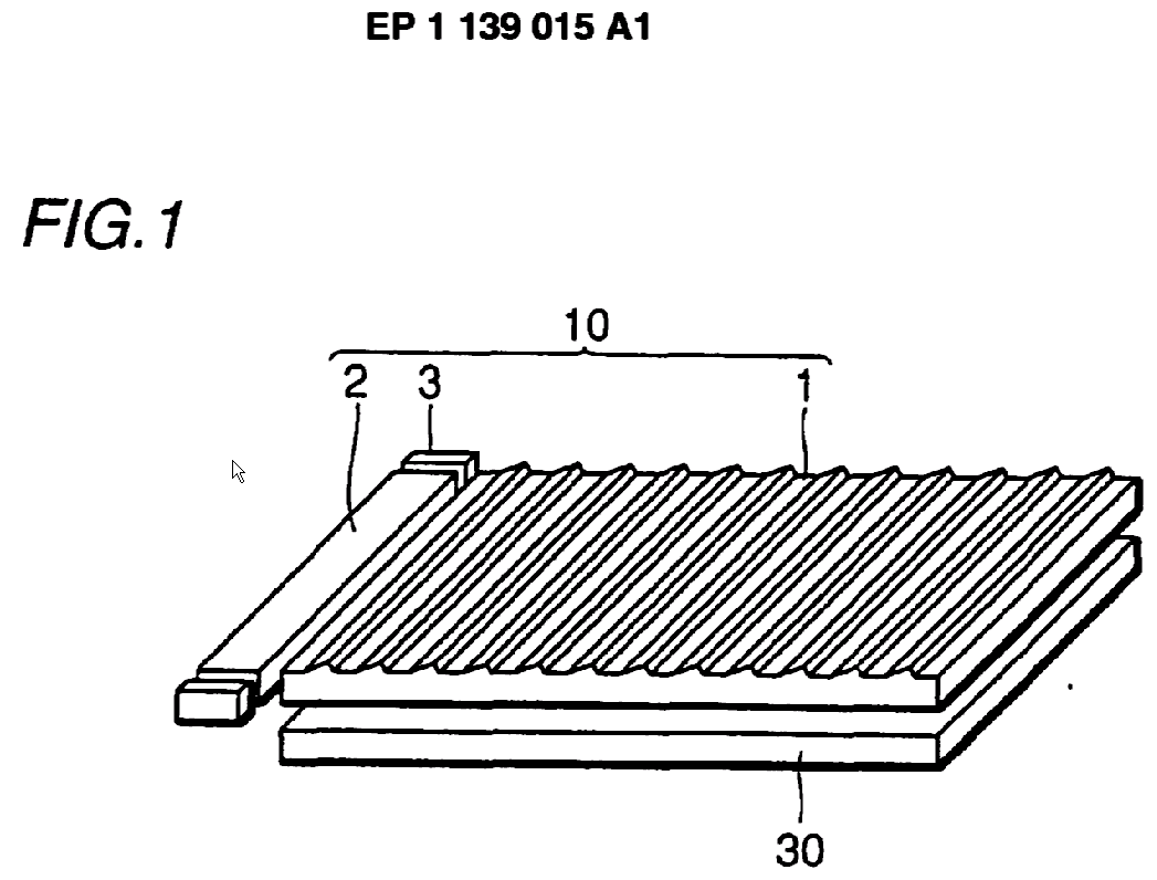
Intermediate light guide rod 2 with sideways coupling into light guide 1. (Source EP 1139015 A1).
Illustrative example of the subject matter classified in this group:
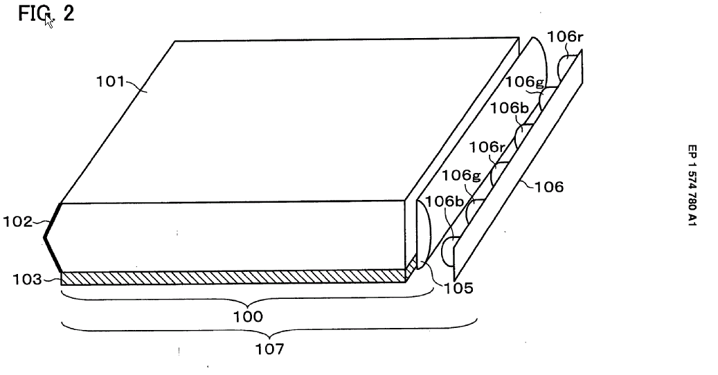
Intermediate lens 105, also used for lens sheets. (Source EP 1574780 A1)
Illustrative example of the subject matter classified in this group:
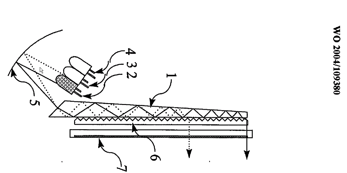
Reflector 5. (Source WO2004/109380).
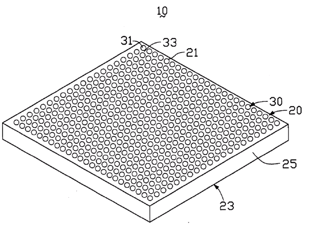
Illustrative example of the subject matter classified in this group:
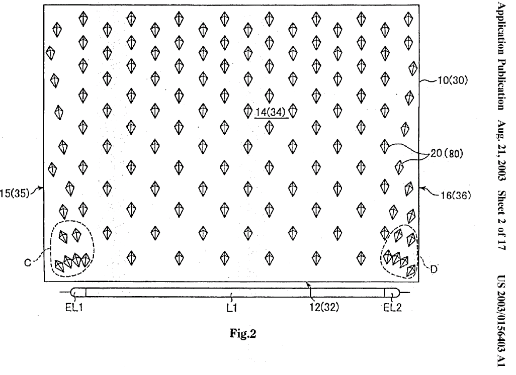
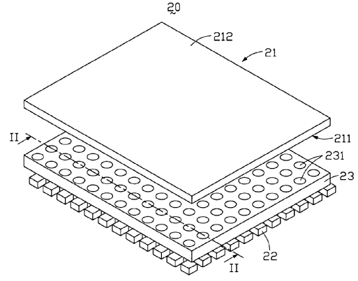
Protrusions 20 arranged in a 2D-array (applied for both regular and irregular arrays). (Source US2003/0156403 A1).
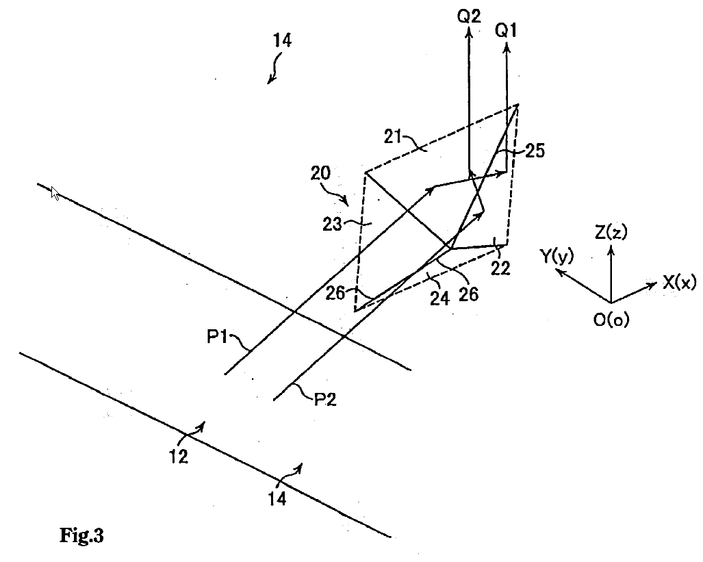
Illustrative example of the subject matter classified in this group:
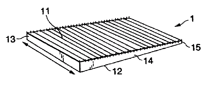
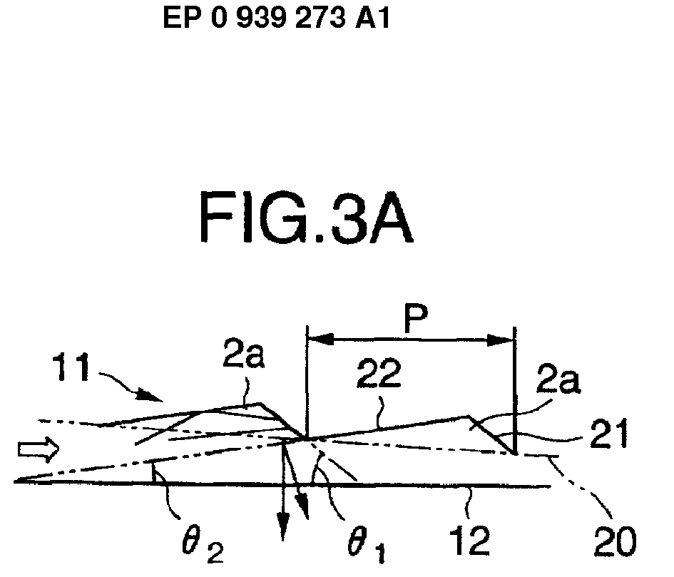
Grooves 11. (Source EP 939273 A1)
Illustrative example of the subject matter classified in this group:
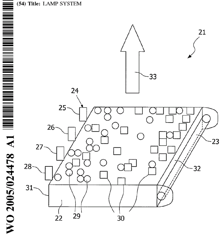
Scattering particles 29, 30 in the bulk. (Source WO2005/024478).
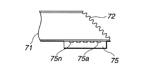
Illustrative example of the subject matter classified in this group:
Scattering dots 31 on the surface of the light guide 20. (Source US 2004/0228109 A1).
Illustrative example of the subject matter classified in this group:
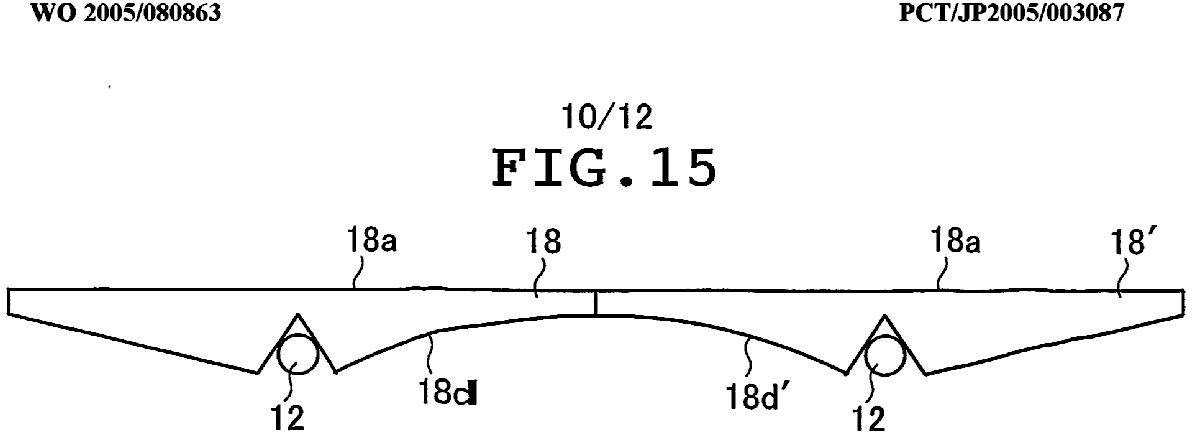
Variation of the thickness of light guide plates. (Source WO2005/080863).
Illustrative example of the subject matter classified in this group:
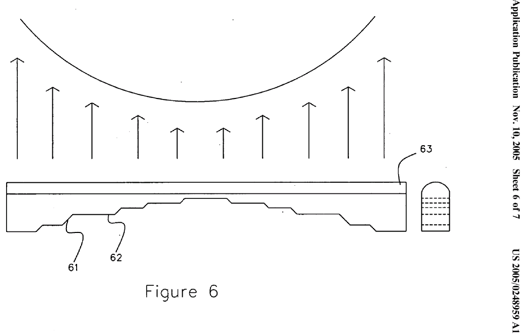
Stepped variation of the thickness of light guide plates. (source US2005/0248959 A1).
The mere indication that a diffusion film, a prism film or a reflecting film is present does not justify classifying in G02B 6/005 and its subclasses. At least some details of these elements have to be given in the document.
Illustrative example of the subject matter classified in this group:
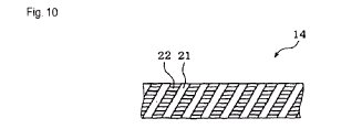 Diffusion film 14. (Source EP 1677047 A1).
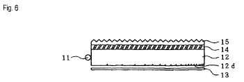
Illustrative example of the subject matter classified in this group:
Prism film 11. (Source WO2005/026793).
Illustrative example of the subject matter classified in this group:
Reflection sheet 5. (Source US 6,486,931 B1).
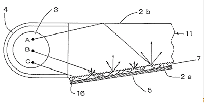
Illustrative example of the subject matter classified in this group:
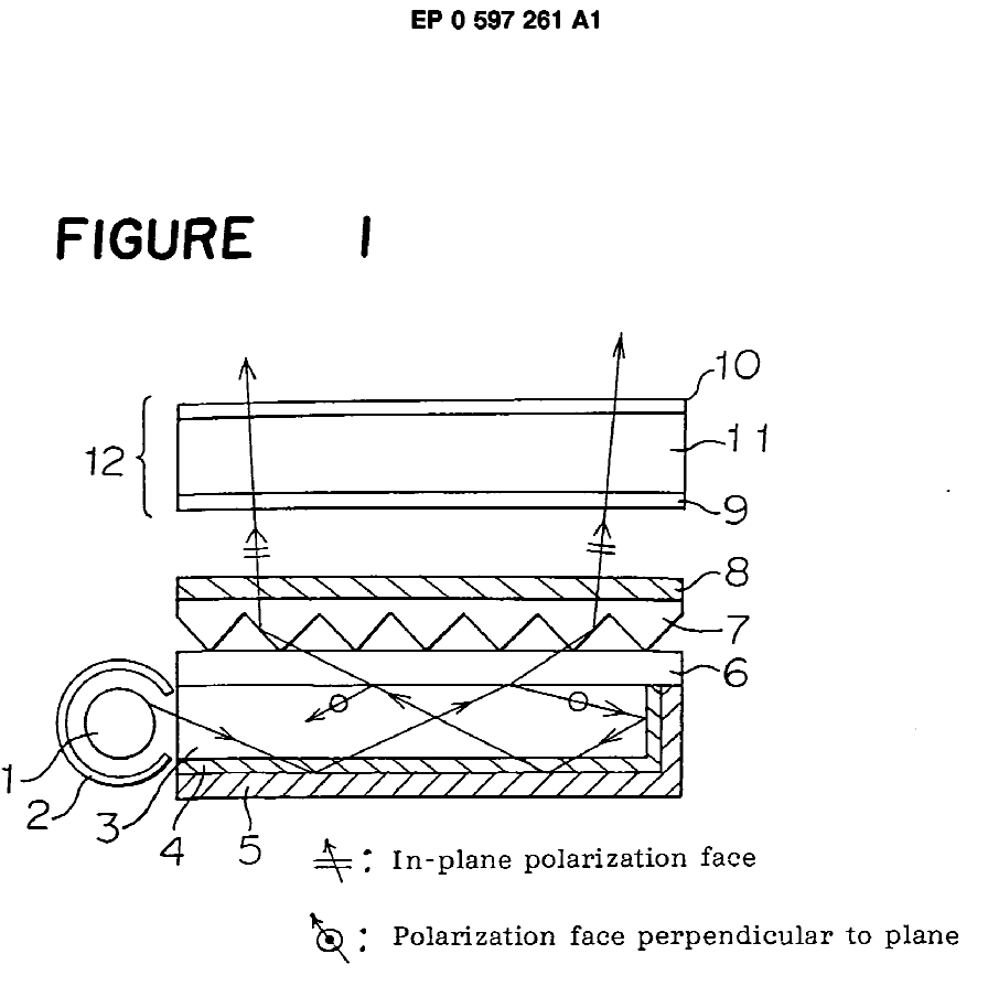 (Source EP 0597261 A1).
Illustrative example of the subject matter classified in this group:
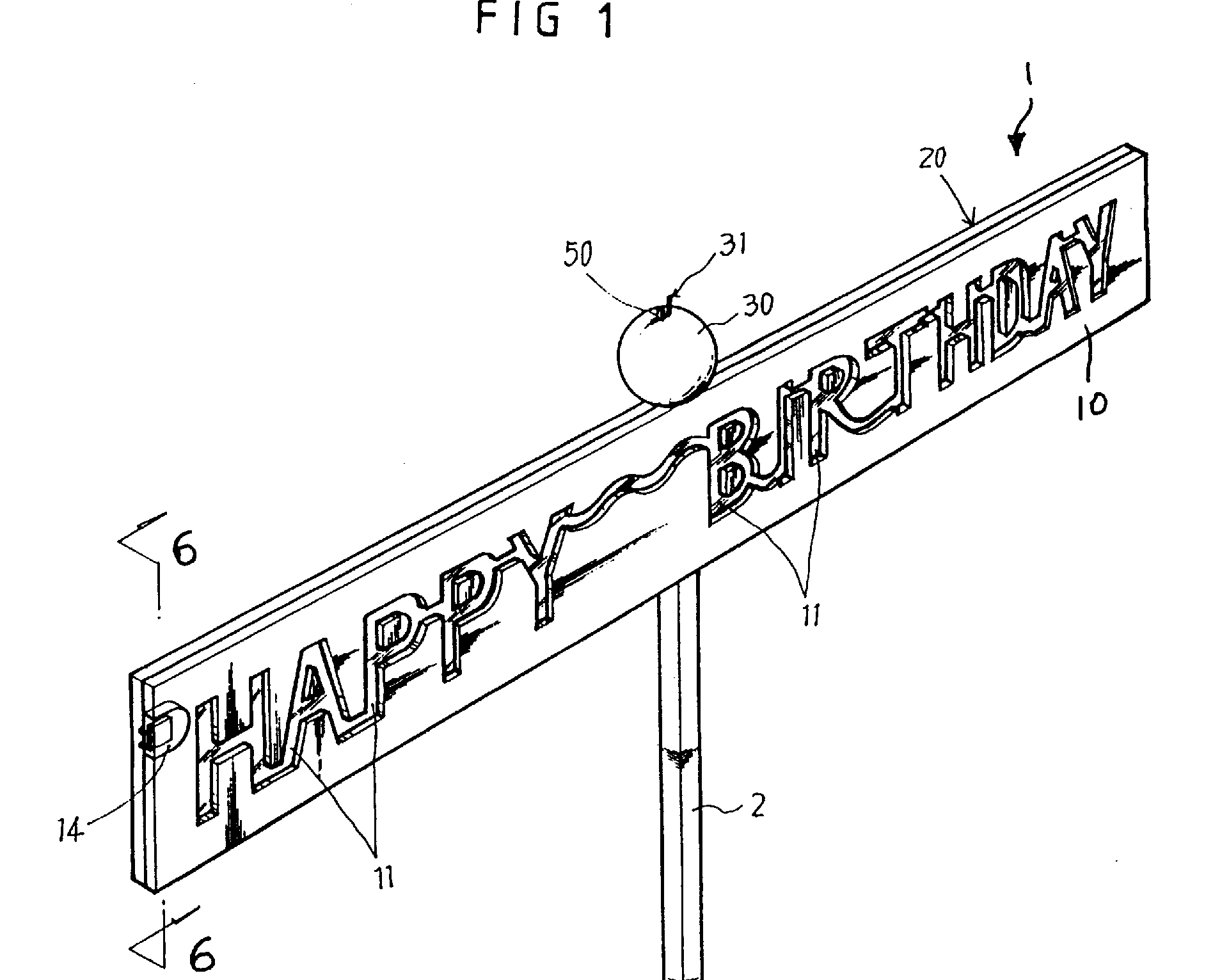
Variations purposely generating inhomogeneous light output, e.g. to display indicia or text. (Source US 5,846,070).
Illustrative example of the subject matter classified in this group:
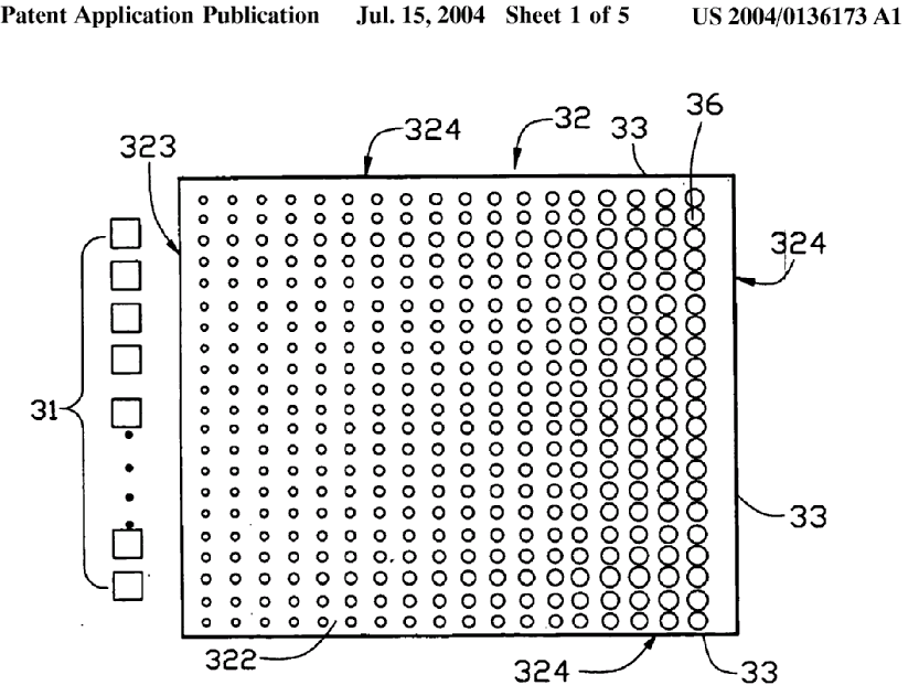
Variations (dot size) to compensate non-uniformities of light propagating in the light guide, so as to achieve homogeneous output intensity. (Source US2004/0136173 A1).
Illustrative example of the subject matter classified in this group:
 Light exits through top and bottom surfaces. (Source DE102004038344 A1).
Manufacturing and material aspects of light guides having one of the features classified in G02B 6/0033 and G02B 6/0013 and lower.
Note: when classifying in this group, classification must also be made in one or more of the groups of G02B 6/0013 or G02B 6/0033 for the related device aspects
Illustrative example of the subject matter classified in this group:
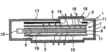
The invention relates to the manufacturing apparatus for surface light source apparatus 10 and includes a pattern design system for designing the light guide pattern portions 15. (Source US 2003/0210539 A1).
Illustrative example of the subject matter classified in this group:
Plural light sources 22. (Source US 2006/0245210 A1).
Illustrative example of the subject matter classified in this group:
Lamp 11. (Source GB 2180051 A).
Illustrative example of the subject matter classified in this group:
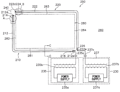
Lamp tubes 212 and 222. (Source US 2003/0198038 A1).
The mere indication that an LED is used does not justify classifying in this group.
Illustrative example of the subject matter classified in this group:
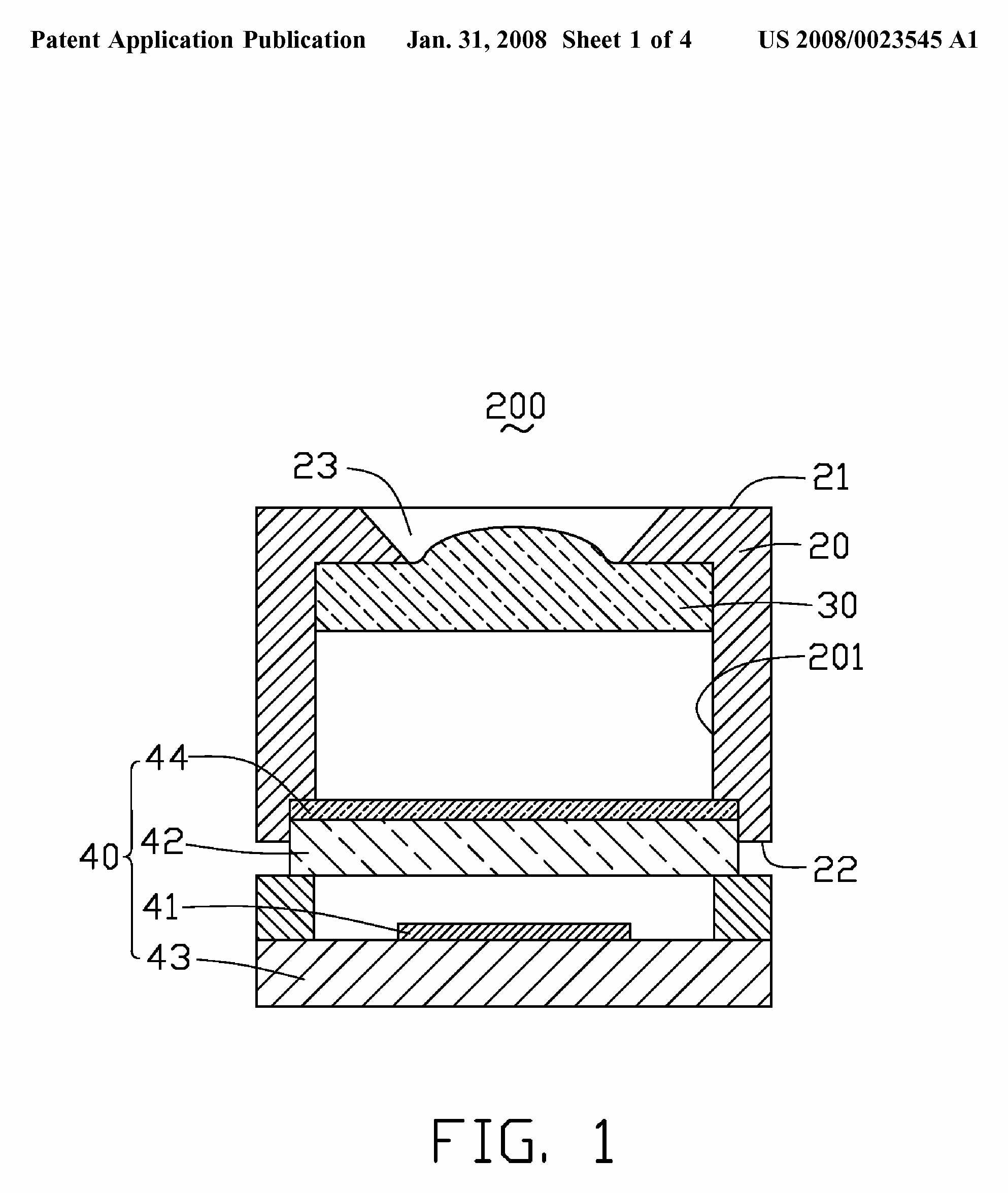
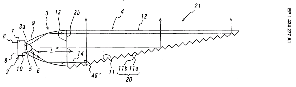 Translucent concave end face 3a has the same curvature as a translucent convex face 6 of the LED lamp 2 (Source EP 1434277 A1).
Illustrative example of the subject matter classified in this group:
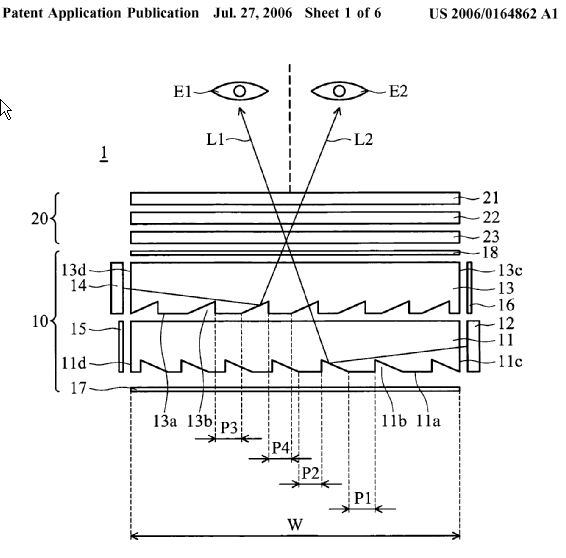
Stacked light guide plates 11 and 13. (Source US 2006/0164862 A1).
Illustrative example of the subject matter classified in this group:
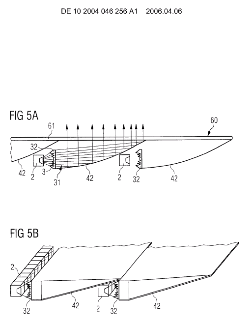
(Source DE 102004046256).
Illustrative example of the subject matter classified in this group:
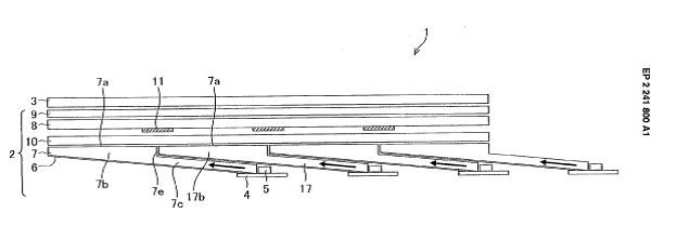
Sections 7b and 7c of adjacent light guides overlap. (Source EP 2241800 A1).
Illustrative example of the subject matter classified in this group:
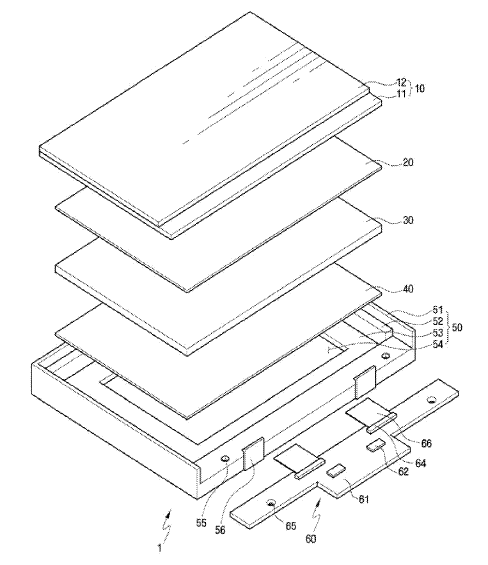
Chips 62, Wiring elements 66. (Source US 2010/0246209 A1).
Illustrative example of the subject matter classified in this group:
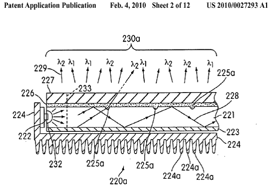
Heat sink 224. (Source US2010/0027293 A1).
Illustrative example of the subject matter classified in this group:
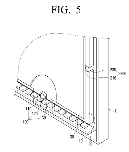
Fixing projections 110, 210 in the housing and support grooves 130, 230 in the light guide for fixing the light guide in the housing. (Source EP 2259104 A2).
Illustrative example of the subject matter classified in this group:
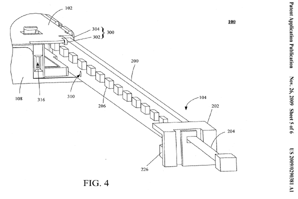
Guiding structure 300 and securing device 202 for fixing the light source in the housing. (Source US2009/0290381 A1).
Illustrative example of the subject matter classified in this group:
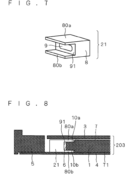
This group is used for devices holding the light source(s) and being directly attached to the light guide, like clamp 8 containing light emitter 9 and being attached to light guide plate 1. (Source US 2007/0285944 A1).
Illustrative example of the subject matter classified in this group:
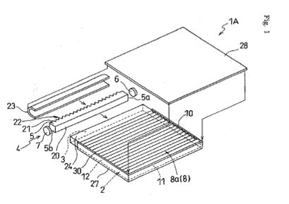
Protective cover 28. (Source EP 1283391 A2).
Illustrative example of the subject matter classified in this group:
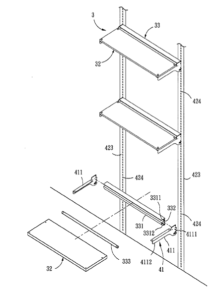
Shelves 32 formed as light guide panels. (Source US 2004/0264161 A1).
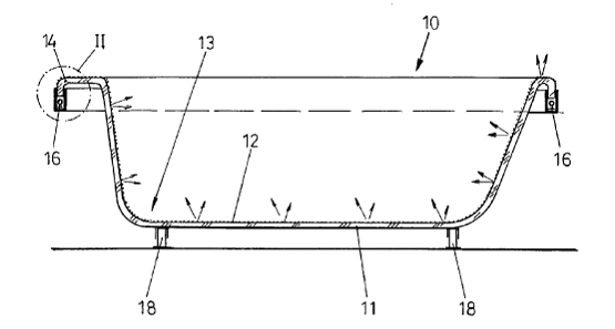
Bath tub with light guide 11 and light source 16. (Source WO 02/100230).
G02B 6/0001 and subgroups include backlights comprising light guides for liquid crystal display panels. Other aspects (other than the light guide) of liquid crystal display backlights are classified in G02F 1/1336. Direct backlights not including a light guide are classified in G02F 1/133602
Attention is drawn to the following places, which may be of interest for search:
Lighting or signalling on vehicles using light guides | |
Lighting devices for vehicle dashboards | |
Lighting devices for vehicle interior using light guides | |
Lighting devices mounted on the vehicle rear part using light guides | |
Measuring arrangements having light conducting pointers | |
Illumination of liquid crystal displays | |
Illuminated signs |
Light guides in the form of long rods for illumination are classified in G02B 6/0005 and subgroups. The Indexing Codes corresponding to G02B 6/0001 - G02B 6/001 and G02B 6/0096 are in F21V 2200/00.
This place covers:
Optical and mechanical properties of optical fibres per se as well as optical fibres with an integral optical element, such as a Bragg grating.
Further details of subgroups
What is considered large or small usually depends on the type of fibre. For example an area of 50 square microns can be considered large for a dispersion compensating fibre (then G02B 6/02009 and G02B 6/02261 should be given) but not large for a non-zero dispersion shifted fibre (i.e. not classified in G02B 6/02004).
Graded multimode plastic optical fibres are classified in G02B 6/02038 not G02B 6/0288. Fibres compensating modal dispersion are usually classified in G02B 6/0288 or G02B 6/02038 as they typically involve a graded index multimode fibre. 1 mm core graded POF is classified in G02B 6/02038.
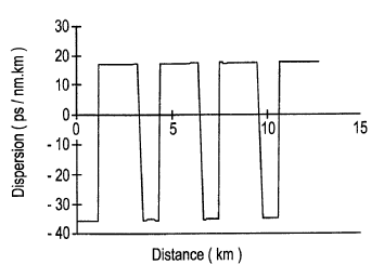
G02B 6/02214 is for dispersion tailoring only at wavelengths other than around the 1550nm window (e.g. for 850 nm, 1300 nm). G02B 6/02223 is for dispersion tailoring at 1550nm and another wavelength, e.g. 1300 nm, in the same optical fibre.
Illustrative example of the subject matter classified in this group:
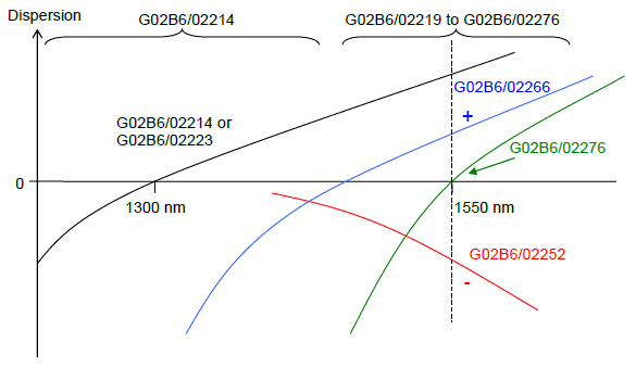
The preceding image includes references to G02B 6/02214, G02B 6/02219, G02B 6/02276, G02B 6/02223, G02B 6/02266, G02B 6/02276, G02B 6/02252.
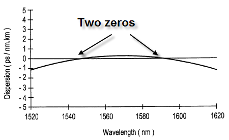
Illustrative example of the subject matter classified in this group:
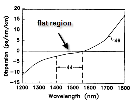
Illustrative example of the subject matter classified in this group:
Illustrative example of the subject matter classified in this group:
Graded multimode plastic optical fibres are classified in G02B 6/02038 not G02B 6/0288. Fibres compensating modal dispersion are usually classified in G02B 6/0288 or G02B 6/02038 as they typically involve a graded index multimode fibre. 1 mm core graded POF is classified in G02B 6/02038.
Illustrative example of the subject matter classified in this group:
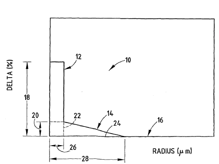
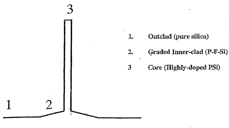
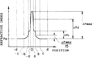
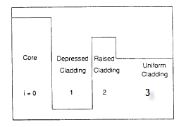
With reference to the notes to G02B 6/03616, graded inner clad 2 is not considered a layer in the sense of G02B 6/03616. Hence these examples are not for G02B 6/03633.
Some documents define the central core as the segment from the centre to where the refractive index delta is zero (e.g. US6421490 defines "the radius from the waveguide centerline to the location of the last refractive index point is the outer radius of the core segment."). The definition in the G02B 6/03616 notes takes precedence.
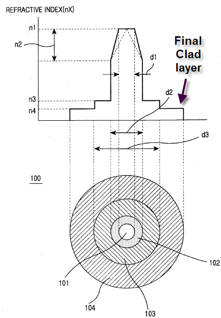
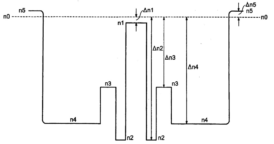
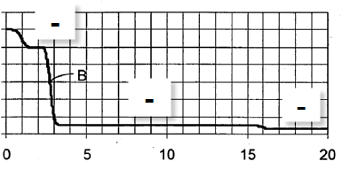
The outer cladding is also considered a layer. If the coating affects the guiding due to its refractive index then it is also considered a cladding layer. Care must be taken not to count beyond the external clad e.g. the following example has 2 clad layers, the top figure can be misleading.
When the profile shows many alternating refractive index layers possibly G02B 6/023 will be relevant.
Illustrative example of the subject matter classified in this group:
Radial asymmetry concept not reflected in lower subgroups.
Illustrative example of the subject matter classified in this group:
Illustrative example of the subject matter classified in this group:
G02B 6/03611 as additional information is used for some documents where the profile has a centreline depression as a result of the manufacturing procedure but there is no purposeful effect on the guiding properties or dispersion properties.
This is however not classified in G02B 6/03611 Since the centreline dip does not affect the optical fibre properties and it is not discussed in the document in detail.
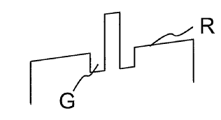
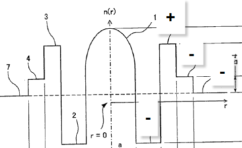
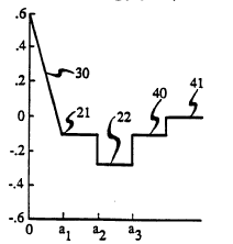
Illustrative example of the subject matter classified in this group:
e.g. W profile
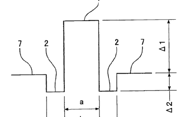 Layers 2 (- relative to central core of width a) and 7 (+ relative to 2).
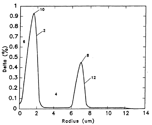
Illustrative example of the subject matter classified in this group:
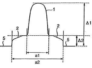
Two layers 2 and 5 around central core segment 1. Layer 2 is a layer in the sense of the G02B 6/03616 definitions, and thus G02B 6/0285 is not appropriate.
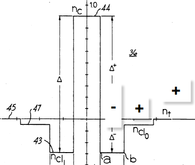
Central core segment between -a and a, first layer (ring) between a and b, second layer (ring) between b and d.
Illustrative example of the subject matter classified in this group:
Illustrative example of the subject matter classified in this group:
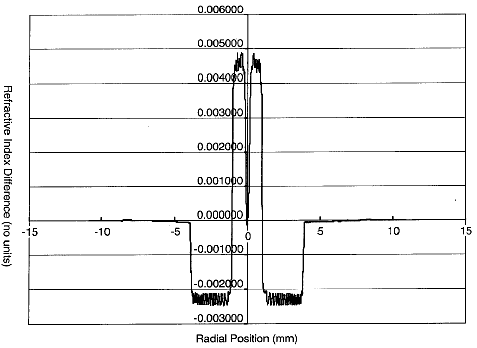
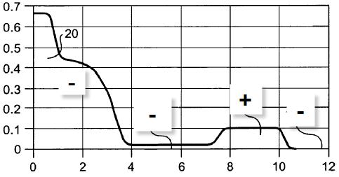
e.g. WT profile
 Layer 1 -, layer 2 +, layer 3 -.
Central core segment 41 (design), 60 (measurement) with three surrounding layers arranged - + -.
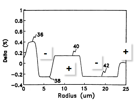
Illustrative example of the subject matter classified in this group:
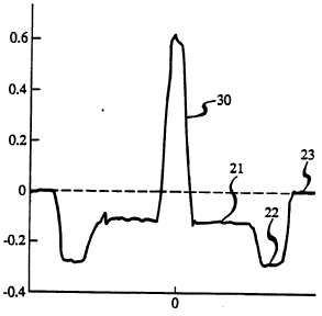 - (21) - (22) + (23).
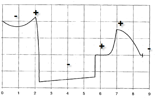
Illustrative example of the subject matter classified in this group:
Illustrative example of the subject matter classified in this group:
Illustrative example of the subject matter classified in this group:
Illustrative example of the subject matter classified in this group:
Illustrative example of the subject matter classified in this group:
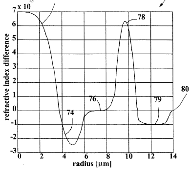
- (74) + (76) + (78) - (79).
Illustrative example of the subject matter classified in this group:
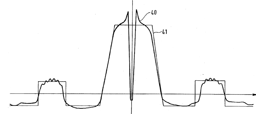
- (21) - (22) + (40) + (41).
Illustrative example of the subject matter classified in this group:
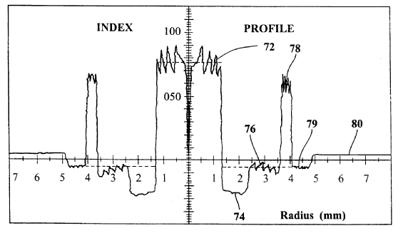
74-80= 5 layers.
6 layers.
Illustrative example of the subject matter classified in this group:
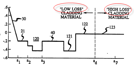
Layers 122 and 123 have the same refractive index but different loss properties.
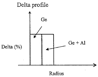
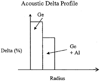
The Ge and Ge+Al l have the same refractive index but different acoustic properties.
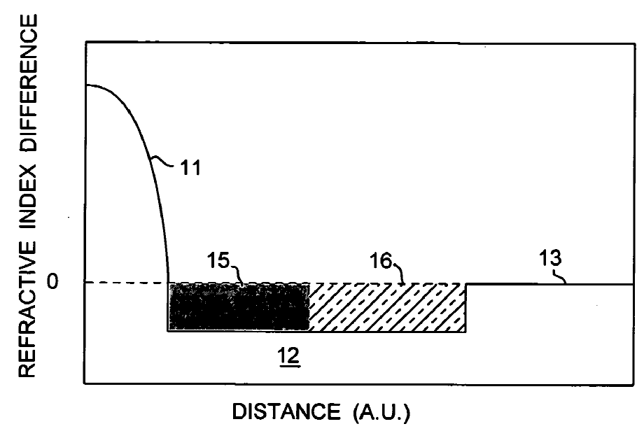 Layers 15 and 16 have the same refractive index but are formed by different methods so that layer 15 has lower losses but takes longer to form.
Indexing Codes
Fluid core or claddings are classified in G02B 6/032 and G02B 2006/0325. No corresponding group exists for Indexing Code G02B 2006/0325.
Attention is drawn to the following places, which may be of interest for search:
Optical fibres for infrared or ultraviolet radiation | |
Optical fibres having polarisation effects except for polarisation maintaining optical fibres | |
Mechanical structures for providing tensile strength and external protection |
All embodiments of patent documents are classified. This is of particular relevance for classifying multilayered optical fibre refractive index profiles in G02B 6/036 - G02B 6/03694.
This place does not cover:
Optical fibres except for infrared and ultraviolet transmitting optical fibres and optical fibres having polarisation effects | |
Optical fibre coupling, and coupling of light guides which are neither of the integrated circuit kind nor for illumination. | |
Devices or arrangements for the control of light by electric, magnetic, electro-magnetic or acoustic means | |
Transferring the modulation of modulated light | |
Optical logic elements | |
Optical analogue/digital converters |
Attention is drawn to the following places, which may be of interest for search:
Light guides for illumination | |
Probes and tips for near field optical microscopy | |
Stores using opto-electronic devices | |
Stores using electro-optical elements | |
Electric waveguides | |
Transmission of information by optical means | |
Optical multiplex systems |
Waveguides which are not of the integrated circuit kind, are not optical fibres and are not used for illumination are classified in the subgroups G02B 6/10 - G02B 6/107. There are three exceptions: the subgroups G02B 6/102 and G02B 6/105 include both optical fibres and waveguides of the integrated circuit kind, and G02B 6/107 includes all sub-wavelength diameter waveguides.
This place covers:
Light guiding paths in an integrated circuit, particularly waveguides formed in a planar substrate, including single paths as well as multiple paths which interact with each other with or without optical elements in or between the light guiding paths. This subgroup further covers methods of producing the waveguides.
This place does not cover:
Electric integrated circuits |
Attention is drawn to the following places, which may be of interest for search:
Photonic crystals not for waveguiding | |
Surface plasmon devices not for light guiding | |
Planar waveguides for infrared or ultraviolet radiation | |
Planar waveguide paths having polarisation effects | |
Sub-wavelength diameter waveguides | |
Coupling fibres and integrated optical circuits | |
Production or processing of single crystals | |
Optical analysis of materials by means of surface plasmons | |
Semiconductor devices sensitive to light | |
Semiconductor devices for light emission |
Wavelength selective arrangements are classified in G02B 6/12007 with the corresponding Indexing Code symbols G02B 6/293 - G02B 6/29398 assigned. For example a planar waveguide arrangement of ring resonators for wavelength selection is classified in G02B 6/12007 and G02B 6/29338.
The coupling of light within planar waveguide substrates is classified in G02B 6/12 and subgroups. Coupling light into or out of an integrated circuit having light guiding paths is classified in the appropriate one of G02B 6/26, G02B 6/30 - G02B 6/305, G02B 6/34, G02B 6/3596, G02B 6/42 and G02B 6/43.
Indexing Codes
G02B 2006/12085 - G02B 2006/12092, G02B 2006/12111 and G02B 2006/12035 are inactive, i.e. they contain some documents but are not used for classification of new documents.
Some of the remaining Indexing Codes correspond to groups as shown in the table below.
The Indexing Codes G02B 2006/12095 - G02B 2006/12104, G02B 2006/12109, G02B 2006/12114 - G02B 2006/12128, G02B 2006/12135 - G02B 2006/12161, G02B 2006/12169, G02B 2006/12173, G02B 2006/12192 and G02B 2006/12197 are used for additional details not listed in the G02B 6/12 subgroups, for example a bent planar waveguide is classified in group G02B 6/125 and with Indexing Code G02B 2006/12119.
The status of the use of the Indexing Codes G02B 2006/12083 - G02B 2006/12197 is shown in the table below:
Inactive | |
Inactive | |
Inactive | |
Inactive | |
Inactive | |
Additional detail | |
Additional detail | |
Additional detail | |
Additional detail | |
Additional detail | |
Additional detail | |
Inactive | |
Additional detail | |
Additional detail | |
Additional detail | |
Additional detail | |
Additional detail | |
Additional detail | |
Additional detail | |
Inactive | |
Additional detail | |
Additional detail | |
Additional detail | |
Additional detail | |
Additional detail | |
Additional detail | |
Additional detail | |
Additional detail | |
Additional detail | |
Additional detail | |
Additional detail | |
Additional detail | |
Inactive | |
Additional detail | |
Additional detail | |
Additional detail | |
Additional detail |
Attention is drawn to the following places, which may be of interest for search:
Coupling of light guides of the planar or plate like form for lighting devices or systems | |
For electric wave guides |
Mechanical coupling aspects of optical elements other than the light guides is classified in the subgroup relating to the optical coupling. For example the mechanical coupling of a fixed reflective bulk diffraction grating between optical fibres is classified in G02B 6/2931, and mechanical means for holding a lens between an optical fibre and an opto-electronic element are classified in G02B 6/4204.
The mechanical coupling of light guides is classified in G02B 6/36-G02B 6/406 and/or G02B 6/42-G02B 6/43. When the mechanical coupling is for a particular type of optical coupling between light guides then the appropriate one of G02B 6/26-G02B 6/3596 is also given. For example a lens coupling together light guides which are mechanically coupled on a substrate is classified in G02B 6/36 - G02B 6/3696 and G02B 6/32.
Attention is drawn to the following places, which may be of interest for search:
Making optical fibres with heat application |
This place covers:
The optical coupling of light into, out of or between light guides.
Further details of subgroups
Illustrative example of the subject matter classified in this group:
(Source US6208442).
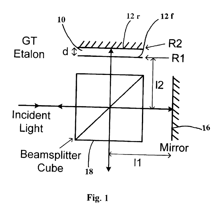
NOTE US6804057 not for G02B 6/29302 as wavelength selection based on etalons not wavelength dependent polarisation effect
See additional explanation in the special rules section for more details relating to separation between G02B 6/29305 and G02B 6/29316 (concerning diffractive elements attached to optical fibres)
Free space means not confined, not necessarily that there is no material
Bulk grating 25. (Source WO0137021).
Illustrative example of the subject matter classified in this group:
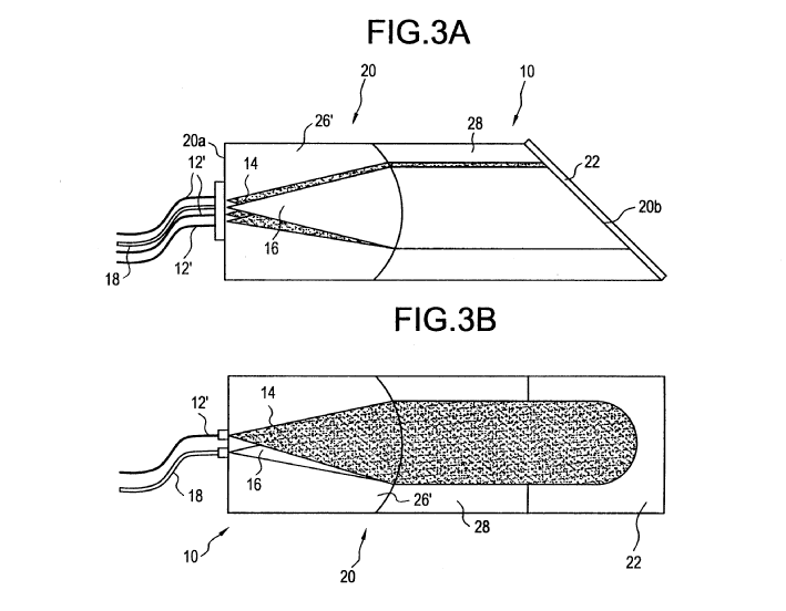
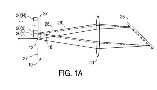
Transparent block formed of 26', 28 and 22. (Source WO9931532).
Illustrative example of the subject matter classified in this group:
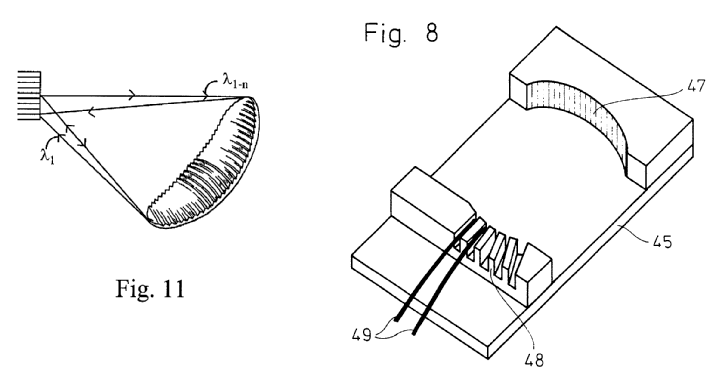
Curved bulk grating 47. (Sources US2002181856 for fig. 11, US4784935 for fig.8).
Illustrative example of the subject matter classified in this group:
(Source WO0137021).
Illustrative example of the subject matter classified in this group:
Transmissive grating 9. (Source WO0029888).
Illustrative example of the subject matter classified in this group:
Adjustable support 14 for positioning optical fibres 5 to 8. (Source US5305402).
Illustrative example of the subject matter classified in this group:
Screw 17 for moving grating 9. (Source US4763969).
includes gratings in contact with the light guide causing diffraction in the light guide, e.g. in contact with the side of a polished fibre (i.e. no free space, no intermediate element other than coupling medium, closely linked to diffractive elements integrated in the light guide) i.e. beam interacting with the diffractive element confined in at least one dimension transverse to propagation. EP1574883 fig. 1 has collimator between fibre and diffractive film thus is not for group G02B 6/29317 (Indexing Code G02B 6/29317 is appropriate). US4148556 fig. 3 is for group G02B 6/29322 as grating is butt coupled.
Illustrative example of the subject matter classified in this group:
Optical fibre 71 with grating 72. (Source US6334014).
Illustrative example of the subject matter classified in this group:
Cascade of optical fibre gratings 325. (Source EP1024378).
Illustrative example of the subject matter classified in this group:
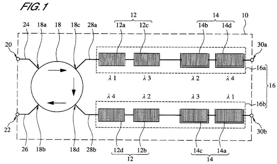
Directional router 18 (circulator) and optical fibre grating cascade 12, 14. (Source EP857988).
Illustrative example of the subject matter classified in this group:
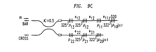
Tunable optical fibre gratings 104 to 109. (Source EP95385).
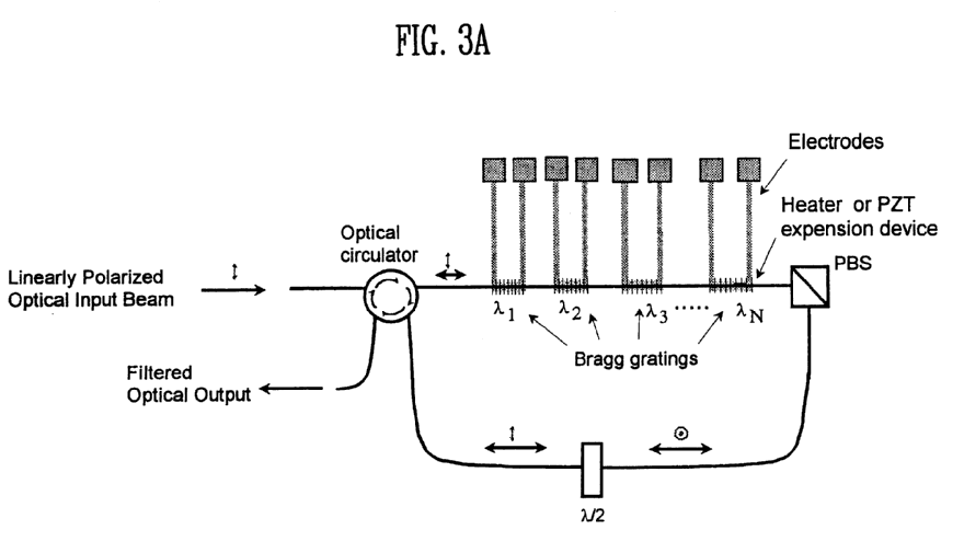
Tunable Bragg gratings (indicated by electrodes). (Source US6097861).
Illustrative example of the subject matter classified in this group:
Light coupled via grating 12 through bottom (lateral) surface of light guide 10. (Source US6016375).
Illustrative example of the subject matter classified in this group:
Slab light guide 50. (Source WO9211517).
Illustrative example of the subject matter classified in this group:
Curved grating 22 on plate light guide 20. (Source US4784935).
Illustrative example of the subject matter classified in this group:
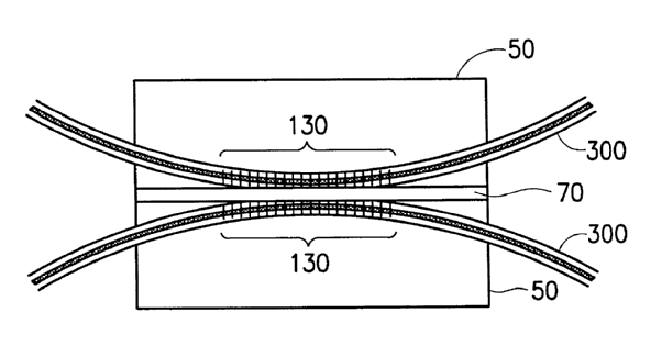
Evanescent coupling in tapered portion 3. (Source EP416537).
Illustrative example of the subject matter classified in this group:
Grating 130 in evanescent coupling region. (Source US20020028040).
Emphasis is on evanescent coupling from a waveguide mode to a resonant mode of a closed loop resonator but see US4720160 fig. 1 where loop resonators are not used. NB in a Sagnac, light only circulates once before interfering thus G02B 6/29347
NOTE: see additional explanation in the special rules section below for more details relating to separation between G02B 6/29335 and G02B 6/29356 or G02B 6/29358 (evanescent and non-evanescent coupling of resonators)
Illustrative example of the subject matter classified in this group:
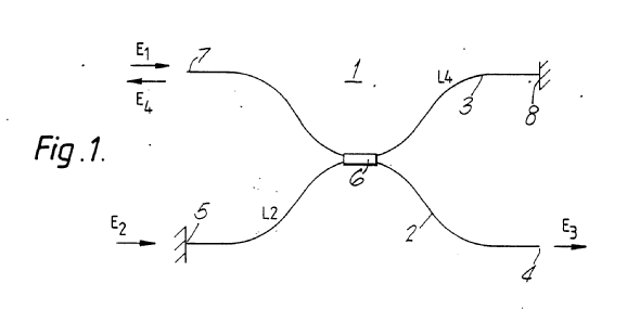
Linear resonator between 5 and 8 coupled via evanescent coupling at region 6. (Source US4859017).
Illustrative example of the subject matter classified in this group:
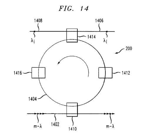
Ring resonator 1404. (Source US6718086).
Illustrative example of the subject matter classified in this group:
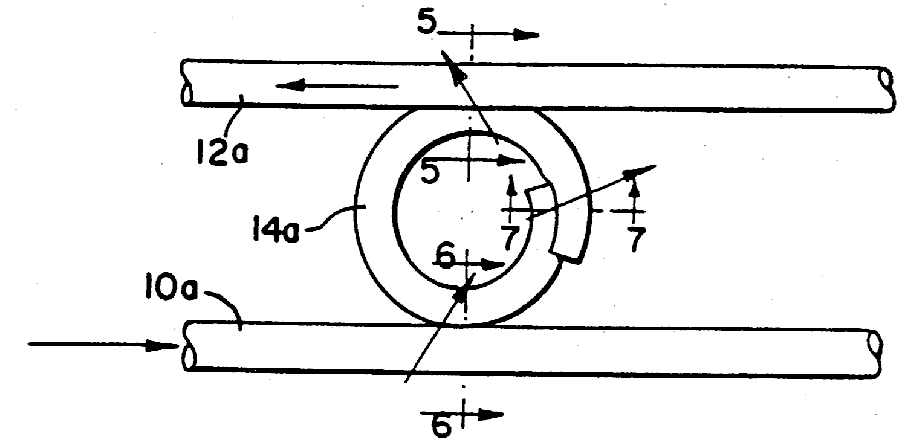
Evanescent coupling to a loop cavity 14a. (Source US4720160).
Whispering gallery mode (WGM) resonance corresponds to light that is trapped in circular orbits just within the surface of the structure. The modes are most strongly coupled along the equatorial plane and they can be thought to propagate along a zig-zag paths around the sphere.
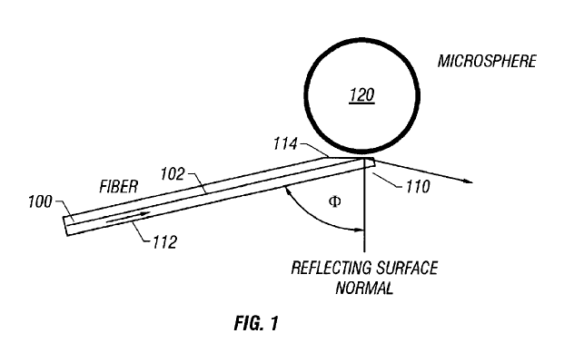
Microsphere 120 supports WGM resonance. (Source US6389197).
(Source US2005128566).
Illustrative example of the subject matter classified in this group:
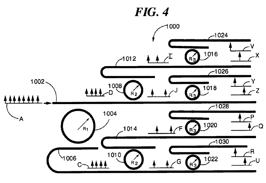
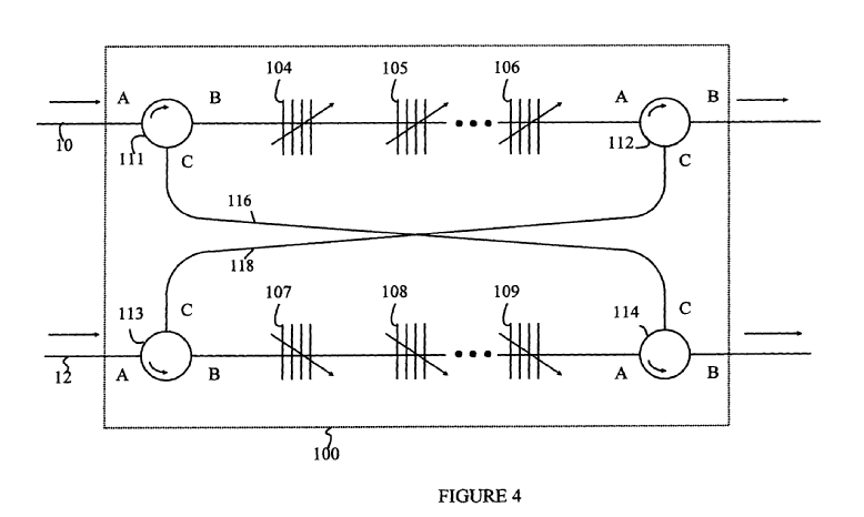
Cascade of loop resonators 1004, 1008, 1016, 1018,1020, 1022. (Source US6643421).
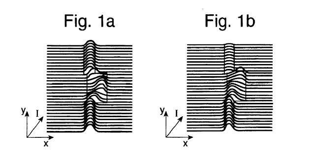
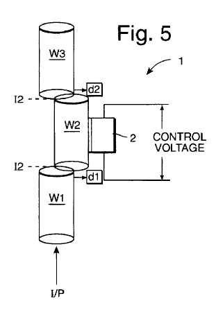
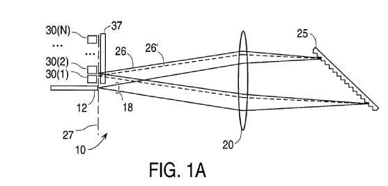
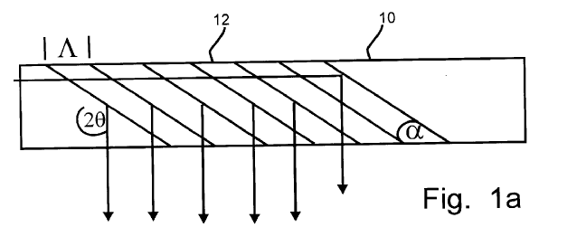
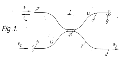
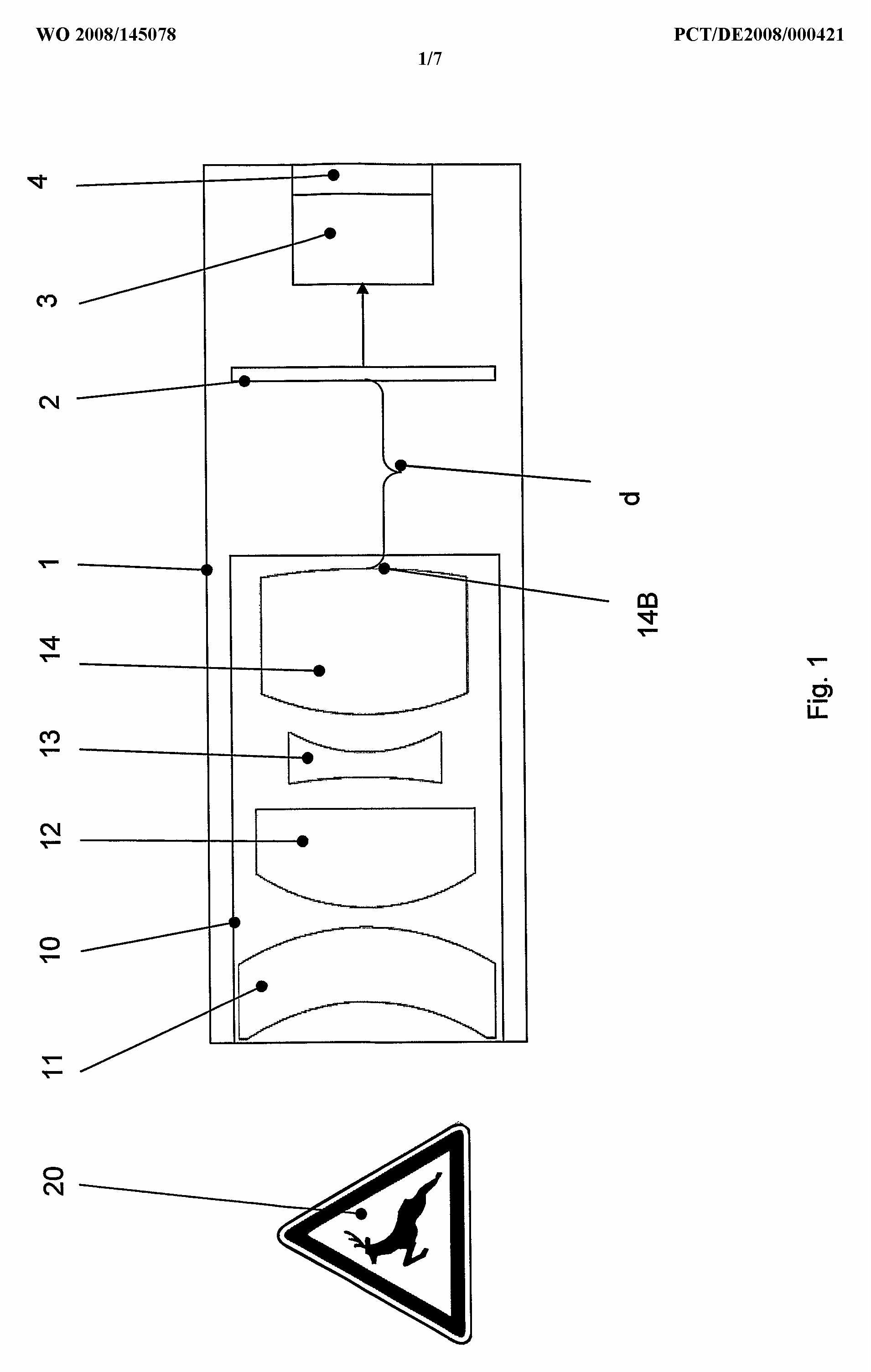
At wavelength L1 shown in FIG. 1a, the dual-mode section W2 is n beatlengths long and the filter (fig. 5) passes radiation. At wavelength L2 shown in FIG. 1b, the dual-mode W2 section is n-1/2 beatlengths long and so radiation is not coupled from the dual-mode filter to the output single-mode filter (W3). (Source US5796891).
Emphasis is on interference between split beams at least one of which travels a loop delay distance
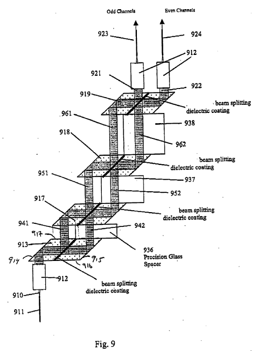
Loops 27 and 37 apply two different delays to beams along optical paths, so that the beams are interfered to form respective output beams corresponding to odd and even communication channels. (Source US2003234935).
Illustrative example of the subject matter classified in this group:
US6252716
(Source US6252716).
Illustrative example of the subject matter classified in this group:
(Source EP1293814).
Illustrative example of the subject matter classified in this group:
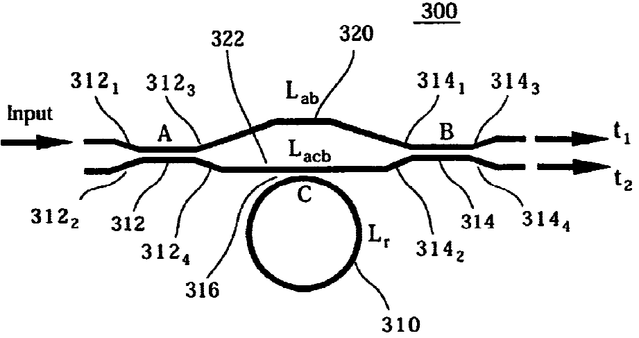
Ring resonator 310 coupled to arm 322 of Mach-Zehnder Interferometer. (Source US6834141).
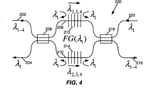
Gratings 212 & 214 in arms 208 & 201 of Mach-Zehnder Interferometer. (Source US2006002653).
Illustrative example of the subject matter classified in this group:
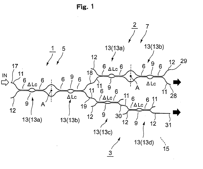
Cascade of Mach-Zehnder Interferometers 13a-13d. (Source WO2005071453).
Illustrative example of the subject matter classified in this group:
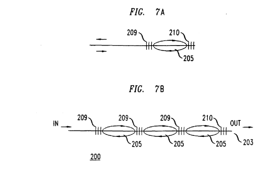
End coupling into cavities formed by reflective gratings 209, 210. (Source EP1024378).
NOTE: see additional explanation in the special rules section for more details relating to separation between G02B 6/29335 and G02B 6/29356 or G02B 6/29358 (evanescent and non-evanescent coupling of resonators)
Interferometer 1. (Source EP1703307).
NOTE: see additional explanation in the special rules section for more details relating to separation between G02B 6/29335 and G02B 6/29356 or G02B 6/29358 (evanescent and non-evanescent coupling of resonators)
Cavity outside light guide, does not include intermediate elements between fibre end face and filter.
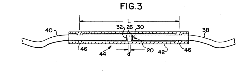
Cavity 26 between mirrors 30 & 32 on ends of light guides 38 & 40. (Source US5202939).
Illustrative example of the subject matter classified in this group:
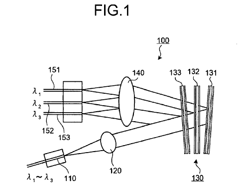
Cascade of filters 131, 132, 133. (Source US2008112668).
Cascade of filters 73 & 75. (Source WO2006080249).
Illustrative example of the subject matter classified in this group:
Cascade of filtering operations on single filter 24 by light guide 12. (Source WO03021319).
Illustrative example of the subject matter classified in this group:
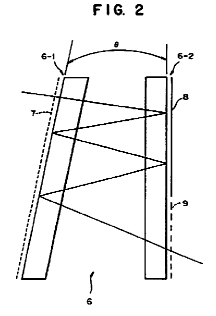
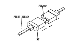
Zigzag path between filter film 7 and reflector film 8. (Source GB2304204).
Illustrative example of the subject matter classified in this group:
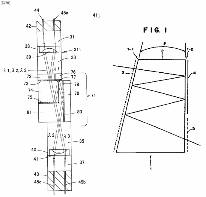
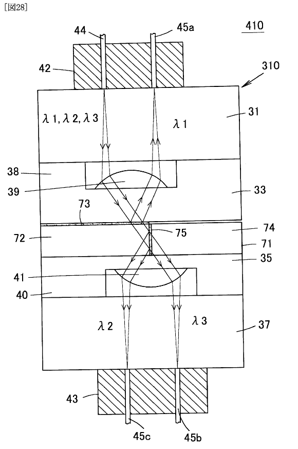
Zigzag path in solid block formed of components 74,78,81 and single solid block 2 (Sources WO2006080249 for fig. 30, GB2304204 for fig. 1).
No coupling optics (such as a lens) between fibre and filter
 (Source Yokosuka et al. Proc. 40th Electronic components and technology conference, May 20-23, 1990, p. 865, XP144764).
Illustrative example of the subject matter classified in this group:
(Source US2004042719)
(Source US2003025967)
Illustrative example of the subject matter classified in this group:
Dispersive prism 3. (Source JP55057804).
Illustrative example of the subject matter classified in this group:
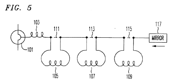
Light guides 103, 105, 107 and 109 with different dispersion. (Source EP0684709).
Illustrative example of the subject matter classified in this group:
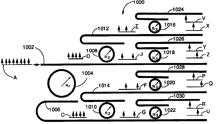
Input signal A demultiplexed into different wavelength signals. (Source US6643421).
Illustrative example of the subject matter classified in this group:
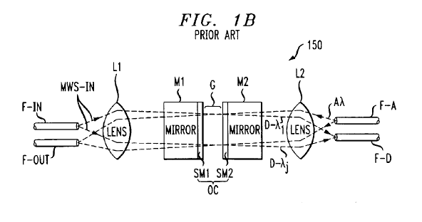
Signal added at F-A and dropped at F-D. (Source US6718086).
Illustrative example of the subject matter classified in this group:
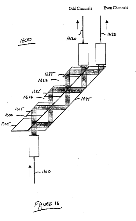
Input signal 1610 de-interleaved into odd and even channels 1620, 1630. (Source EP1293814).
This place does not cover:
Attention is drawn to the following places, which may be of interest for search:
Coupling of light within planar waveguide substrates of the integrated circuit kind | |
Scanning using movable fibres | |
Systems for wavelength dispersion compensation | |
Systems for polarisation mode dispersion compensation | |
Systems for wavelength division multiplexing | |
Optical switching systems |
G02B 6/287 is not used for classification. G02B 6/255, G02B 6/2835, G02B 6/2856 and G02B 6/29331 are used instead.
The following arrangement is observed in relation to optical fibre couplers:
Optical fibre couplers of the NxN type (e.g. 2x2) | |
Optical fibre couplers of the 1xN type formed by thermal treatment |
Prisms or gratings coupled to light guides for purposes other than wavelength selection are classified in G02B 6/34.
Systems for wavelength division multiplexing based on optical fibres are classified in H04J 14/02, H04J 14/03, H04J 14/0305 and H04J 14/0307. Reference is made to the section "Relationship between large subject-matter areas" under G02B 6/00.
Planar waveguides
Couplings between separate planar waveguide substrates, e.g. using intermediate bulk optics, are classified in G02B 6/26. Planar waveguide couplings are also classified in G02B 6/30-G02B 6/305, G02B 6/34, G02B 6/3596, G02B 6/42 and G02B 6/43.
G02B 6/262-G02B 6/29398, G02B 6/32-G02B 6/327 are restricted to light guides of the optical fibre type.
The coupling of light within planar waveguide substrates is classified in G02B 6/12 and subgroups. For example optical fibre couplers are classified in G02B 6/2804 whereas planar waveguide couplers are classified in G02B 6/125. The one exception is G02B 6/3596.
In G02B 6/35 and subgroups a single subgroup is assigned (the most relevant) with further aspects classified in the Indexing Code.
Indexing Codes
No groups correspond to Indexing Codes G02B 2006/2839 and G02B 2006/2865.
Separation between G02B 6/29305 and G02B 6/29316
G02B 6/29305 is for bulk diffraction elements (gratings) with free space between the light guide and grating. This means that before interacting with the grating the light beams are not guided in the light guide for a certain distance (or vice-versa).
G02B 6/29316 is for light guides comprising the grating. This means there is no free space between the light guide and the grating and the light beams are guided in the light guide onto the grating (or vice-versa).
Examples.
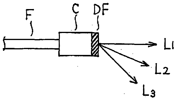
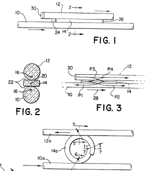
Diffractive film DF is on a collimator C. (Source EP1574883).
Butt coupled grating 50, no free space to light guide 42. (Source US4148556).
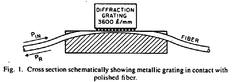
No free space between grating and fiber. (Source Sorin et al. in Journal of Lightwave Technology, Vol. LT-3, Oct 1985, p. 1041, XP1652325).
Separation between G02B 6/29346 and G02B 6/29335
Parallel plate resonators can be in either G02B 6/29358 or G02B 6/29335 - the correct group depends on how the resonator is coupled to the light guide.
Where light is coupled into the resonator from the light guide by evanescence G02B 6/29335 is appropriate (i.e. the evanescent field of the light guided in the light guide overlaps with the resonant mode of the resonator). This is usually the case with lateral coupling, but not always.
Examples
US20070104421 in G02B 6/29358
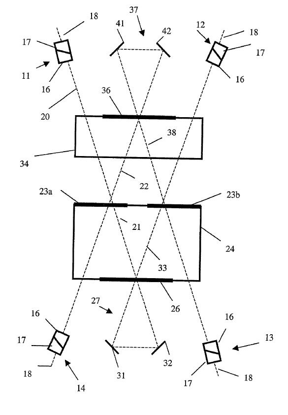
Parallel plate resonators formed by resonator members 18, 19, 28 and 29 external to light guides 13, 23 and light coupled between resonators and light guides by deflector means 16 and 26. (Source US20070104421).
Linear resonator between 5 and 8 coupled via evanescent coupling at region 6. (Source US4859017).
Devices of the type shown in fig. 1-3 below with evanescent coupling to a linear cavity between mirrors 24 & 26 are classified in G02B 6/29337, of the type shown in fig. 4 below with evanescent coupling to a loop cavity 14a are classified in G02B 6/2934
 (Source US4720160).
Devices of the type shown in fig. 6B with evanescent coupling to a cascade of loop resonators 180 are classified in G02B 6/29343. Devices of the type shown in fig. 7A & 9C below with end coupling into cavities formed by reflective gratings (i.e. without evanescent coupling into a resonator cavity) are classified in G02B 6/29356.
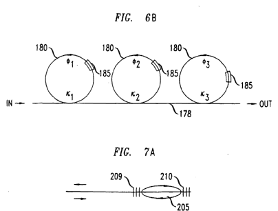
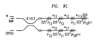
(Source EP1024378).
Attention is drawn to the following places, which may be of interest for search:
Polarising elements in general | |
Polarisation systems in general | |
Optical polarisation multiplex systems |
Attention is drawn to the following places, which may be of interest for search:
Optical wavelength-division multiplexing systems |
This place does not cover:
By changing the optical properties of the medium |
Attention is drawn to the following places, which may be of interest for search:
Optical switching in general |
This place covers:
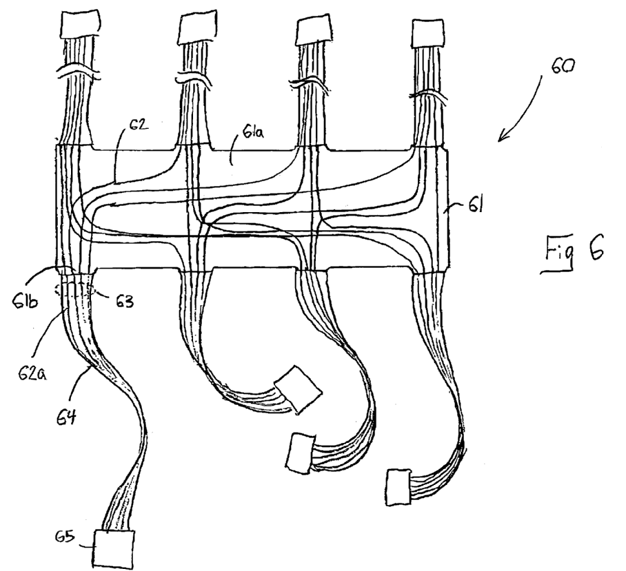
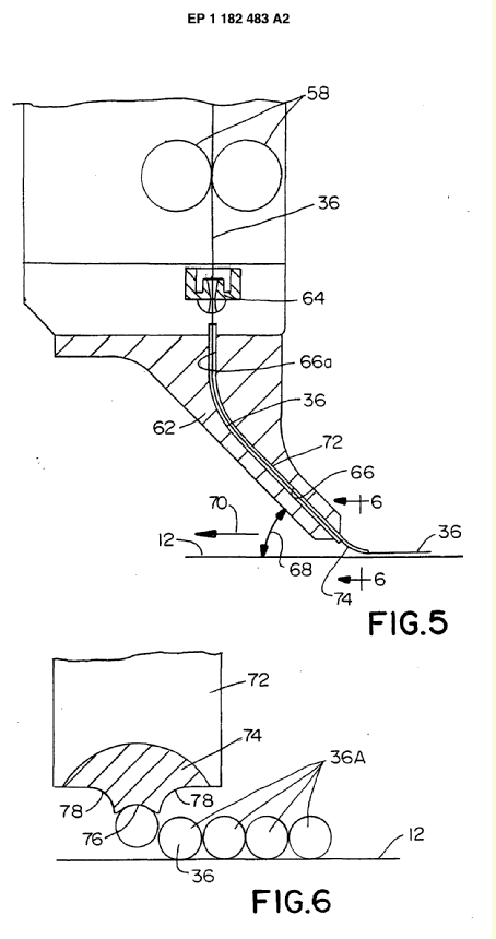
The mechanical coupling of optical fibres, e.g. mechanical means for holding optical fibres on a substrate, and mechanical means such as connectors for the interconnection of optical fibres.
Further details of subgroups
Illustrative example of the subject matter classified in this group:
(Source US2003/0179980).
Illustrative example of the subject matter classified in this group:
(Source EP 1 182 483).
Illustrative example of the subject matter classified in this group:
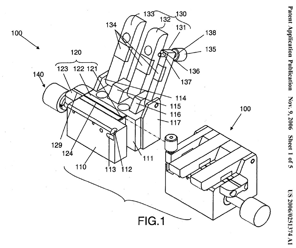
(Source US2006/0251374).
Illustrative example of the subject matter classified in this group:
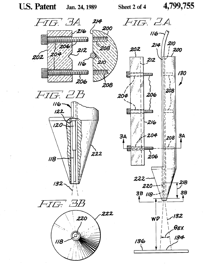
(Source US 4,799,755).
Illustrative example of the subject matter classified in this group:
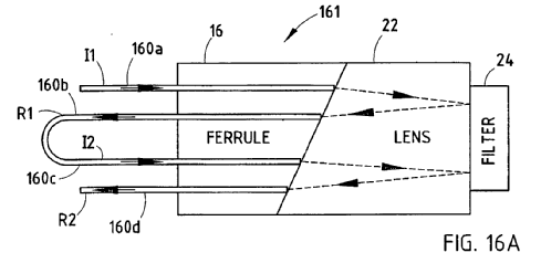
Optical fibre (16). (Source WO03/021312).
Illustrative example of the subject matter classified in this group:
(Source US 2004/0086255).
Illustrative example of the subject matter classified in this group:
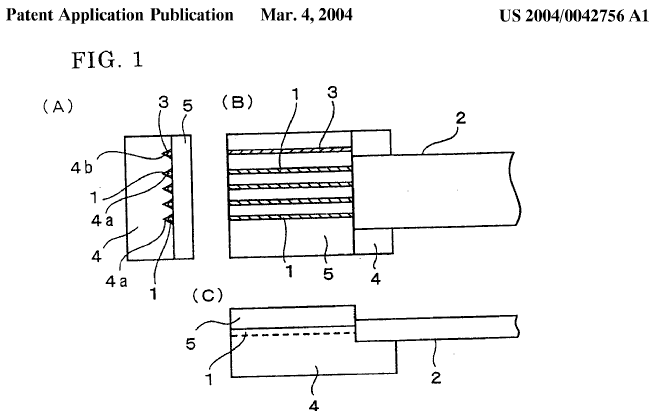
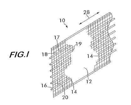
(Source US2001/0042756).
Illustrative example of the subject matter classified in this group:
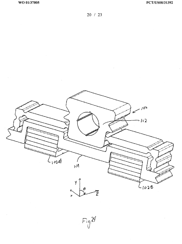
(Source WO01/37005).
Illustrative example of the subject matter classified in this group:
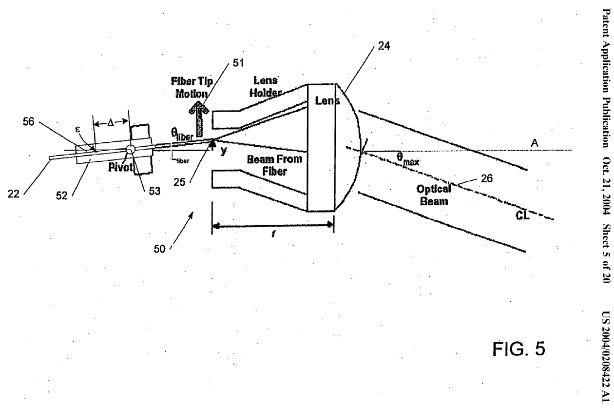
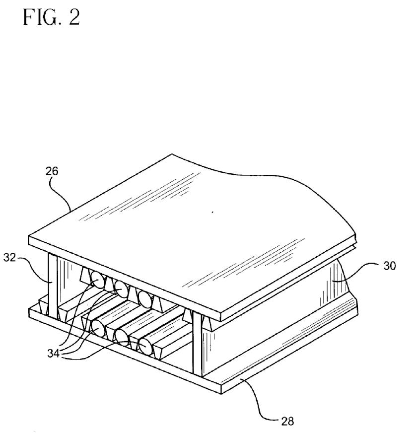
(Source US2004/0208422).
Illustrative example of the subject matter classified in this group:
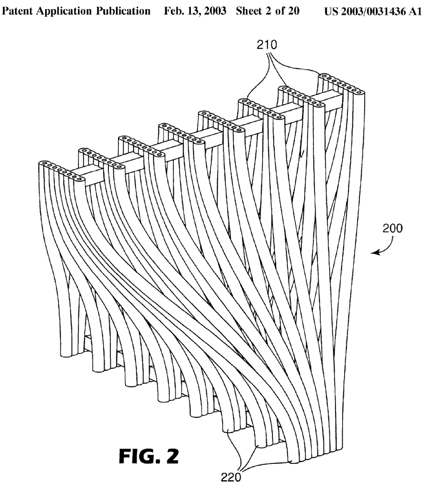
(Source US2003/0031436). (also classified in G02B 6/3676).
Illustrative example of the subject matter classified in this group:
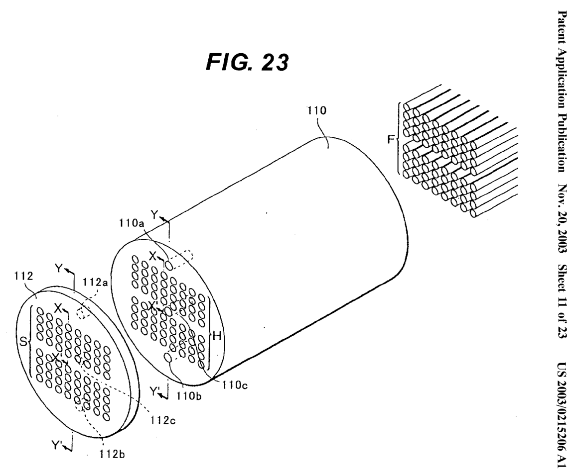
(Source US2003/0215206).
Illustrative example of the subject matter classified in this group:
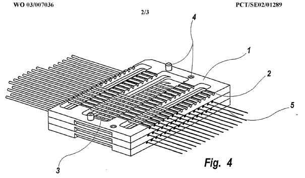
(Source WO03/007036).
Illustrative example of the subject matter classified in this group:
(Source GB2331161).
This place does not cover:
Splicing of light guides by fusion or bonding | |
Coupling light guides with optoelectronic elements |
Attention is drawn to the following places, which may be of interest for search:
Light guides formed by bundle of fibres, the relative position of the fibres being the same at both ends, e.g. for transporting images | |
Optical coupling means for use between fibre and thin-film device | |
Optical coupling means having switching means | |
Optical coupling means having fibre to fibre mating means | |
Cleaning of optical fibres and connectors |
The mechanical coupling between optical fibres or of optical fibres with opto-electronic elements is classified in the appropriate groups of G02B 6/38 - G02B 6/3897 and G02B 6/42-G02B 6/43 and additionally in Indexing Codes G02B 6/3608-G02B 6/3696, especially when the latter are more detailed. Light guides coupled together as a splice by mechanical holding means, i.e. mechanical splices, are classified in G02B 6/3801.
The mechanical coupling of optical fibre cables and the storage of optical fibres is classified in G02B 6/4401 and subgroups.
In G02B 6/3608-G02B 6/3696 as far as possible only one subgroup is assigned with further aspects classified in Indexing Codes G02B 6/3608-G02B 6/3696.
A demountable optical fibre connector is often classified in several of the G02B 6/3807 - G02B 6/3897 subgroups and/or Indexing Codes G02B 6/3807-G02B 6/3897 to reflect the various aspects of the connector. This is especially important to allow retrieval of mechanical configurations which are not easily searchable using words.
Optical fibre connector accessories and tools, e.g. for assembling, insertion or extraction of connectors not provided for elsewhere are classified in G02B 6/3807. The testing of optical fibre connectors is classified in G01M 11/00 and subgroups. Devices for cleaning optical fibre connectors are classified in G02B 6/3807 and circulated to B08B 1/00.
G02B 6/40-G02B 6/403 relate to optical fibre bundles in the sense of G02B 6/04.
Planar Waveguides
The mechanical coupling of planar waveguides is classified in the appropriate one of G02B 6/12-G02B 6/12033, G02B 6/30-G02B 6/305, G02B 6/42 and G02B 6/43.
This place does not cover:
Splices by bonding optical fibres together | |
Fusion splices |
This place covers:
Demountable optical fibre connectors presenting a protuding free optical fibre end
Illustrative example of subject matter classified in this group:
(Sources: US5,694,506, FR2818839)
This place covers:
Demountable optical fibre connectors having ferrules.
Illustrative example of subject-matter classified in this group:
Ferrules 11a, 11b. (Source: JPS5674211)
This place covers:
Details of the ferrule, mounting of prepared optical fibre in the ferrule.
This place covers:
Mounting of the assembled fibre and ferrule into the connector body and details of the connector body.
Attention is drawn to the following places, which may be of interest for search:
Beam shaping of a semiconductor light source | |
Beam shaping using a light guide | |
High frequency adaptations of semiconductor devices | |
Semiconductor devices sensitive to light per se | |
Semiconductor devices for light emission per se | |
Semiconductor light sources with optical field shaping elements | |
Electrical conduction aspects of semiconductor light sources | |
Optical interconnects | |
Printed circuit boards | |
Cooling, ventilating or heating electrical apparatus | |
Arrangements for extracting light from an organic light source |
Optical coupling aspects of light guides for illumination are classified in G02B 6/0001 - G02B 6/0096. The coupling of non coherent light, including lamps, into optical fibres for purposes other than illumination is classified in G02B 6/4298.
Electric, thermal and mechanical aspects of packages not covered by G02B 6/4202 - G02B 6/4298 are classified in G02B 6/4201. G02B 6/4201 - G02B 6/4215 also include documents where the light guide is implicit.
The coupling of light guides with opto-electronic elements using a wavelength selective or polarisation selective and adjusting optical element are classified in G02B 6/4215 or G02B 6/4246 and the relevant G02B 6/27 - G02B 6/2793 and/or G02B 6/293 - G02B 6/29398, since the latter are more detailed.
Mechanical coupling aspects of optical fibre arrangements classified in G02B 6/42 - G02B 6/43 are additionally classified in G02B 6/36 - G02B 6/3696 especially when the latter are more detailed.
Connector aspects of disconnectable light guide arrangements classified in G02B 6/4292 are also classified in G02B 6/3807 - G02B 6/3897 and/or G02B 6/3807 - G02B 6/3897.
Planar Waveguides
Planar waveguides coupled with optoelectronic elements are classified in G02B 6/42 with G02B 6/4201 - G02B 6/4296 assigned for the details (e.g. G02B 6/42 and G02B 6/4214), however monolithic configurations, i.e. where the planar waveguide and optoelectronic element are grown on the same substrate are classified in G02B 6/12004.
Indexing Codes
G02B 6/4292 has the additional Indexing Code G02B 2006/4297 for protection means, e.g. using shutters to avoid inadvertent exposure
Attention is drawn to the following places, which may be of interest for search:
Light-emissive or light-sensitive semiconductor devices | |
Semiconductor lasers monolithically integrated with other components |
This place does not cover:
Cables incorporating electric conductors and optical fibres (where features relating to the optical fibres are not of interest) |
G02B 6/4439 - G02B 6/44785 are also used for classifying auxiliary devices with uncabled optical fibres. For example the storage of optical fibres in spools is classified in G02B 6/4457.
Optical cable installations in buildings, for example over multiple floors, are classified in G02B 6/475.
This place does not cover:
Installation of cables containing electric conductors and optical fibres |
This place covers:
Mountings, adjusting means, including means for effecting focusing and zooming, and light-tight connections for optical elements like lenses, prisms or mirrors or the like.
The following simplified arrangements are to be observed in relation to mechanical aspects of focusing and zooming (G02B 7/04):
- Non-zoom systems: Manual focusing: G02B 7/04
- Non-zoom systems: Automatic (motorized) focusing: G02B 7/08
- Zoom systems: Manual focusing and zooming: G02B 7/10
- Zoom systems: Automatic (motorized ) focusing and zooming: G02B 7/102
- G02B 7/10 and G02B 7/102 relate to the mechanical aspects of zoom lenses (e.g. cam arrangements). The optical aspects of the design of zoom lenses are covered by G02B 15/00.
The following IPC subclasses are not used for classification: G02B 7/185 - G02B 7/198 (subject-matter covered by G02B 7/182 and other subgroups of G02B 7/182).
Attention is drawn to the following places, which may be of interest for search:
Optical devices or arrangements using movable or deformable optical elements for controlling the intensity, colour, phase, polarisation or direction of light |
Attention is drawn to the following places, which may be of interest for search:
Mirrors with curved faces |
Examples of places where the subject matter of this place is covered when specially adapted, used for a particular purpose, or incorporated in a larger system:
This place covers:
Optical objectives characterised both by the number of the components and their arrangements according to their sign, i.e. + or -. The plus (+) symbol represents a positive lens, and the minus (-) symbol represents a negative lens
This place does not cover:
Optical objectives with means for varying the magnification |
This place covers:
Optical objectives specially designed for specific purposes.
Further details of subgroups
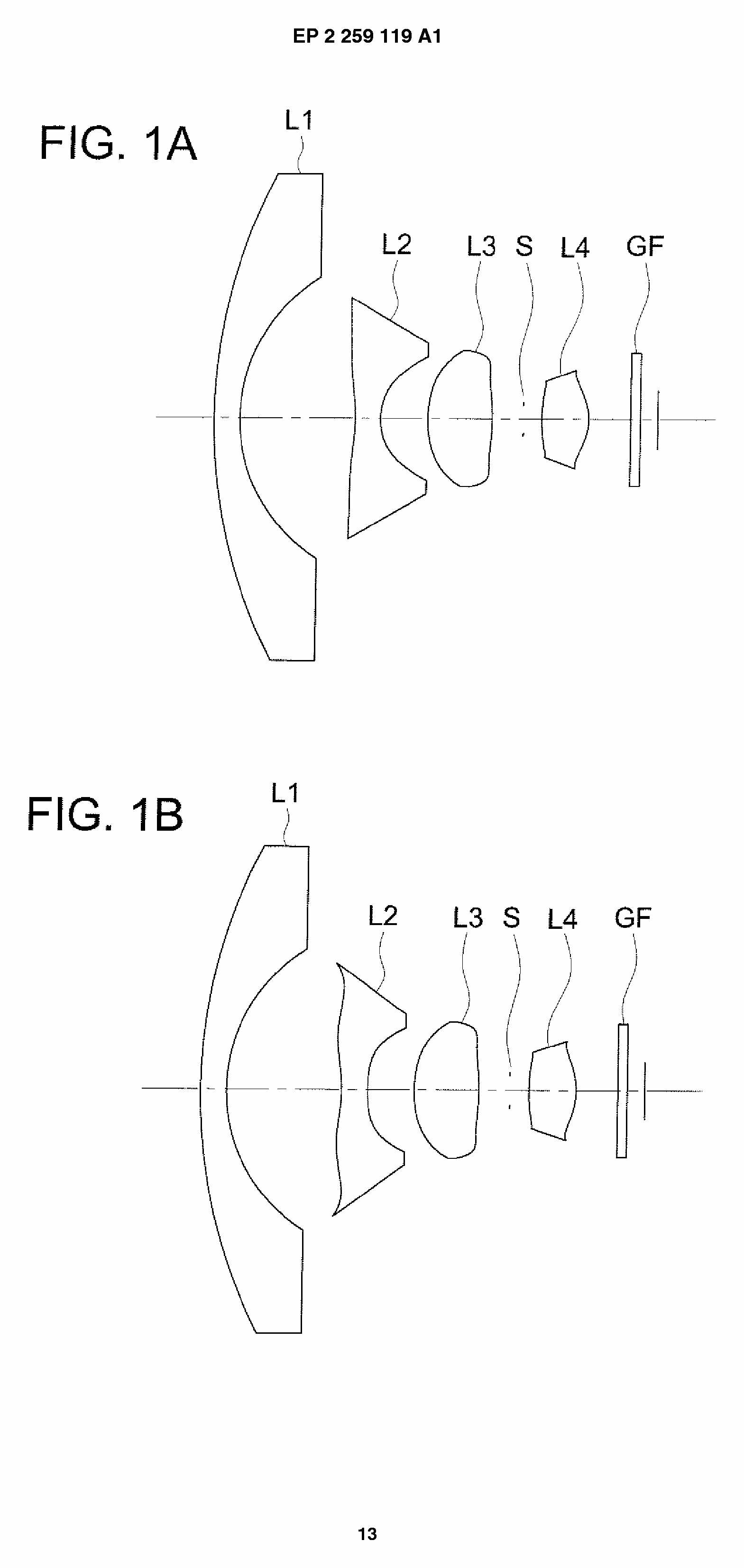
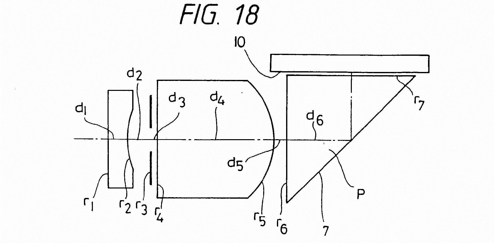
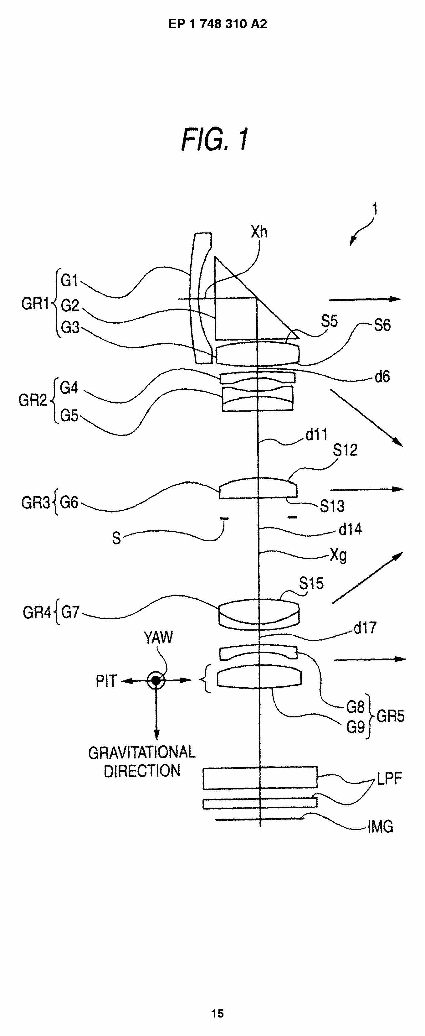
Concerning the subgroup G02B 13/001 (miniaturised objectives for electronic devices, e.g. portable telephones, webcams, PDAs, small digital cameras), symbols from G02B 13/0015 and G02B 13/0055 will usually be assigned. In G02B 13/002, one compound lens counts as one lens. The symbol G02B 13/006 indicates the presence of a compound element. The following figures illustrate typical examples of the subject-matter found in the indicated subdivisions:
Attention is drawn to the following places, which may be of interest for search:
With variable magnification in general |
With the exception of G02B 13/06, optical objectives having reflecting surfaces are not classified under G02B 13/00, but under G02B 17/00.
Unless specified in the title of the subgroups, this group and its subgroups do not cover objectives comprising reflecting surfaces, which are covered by G02B 17/06, G02B 17/08 and their subgroups
This place covers:
Illustrative example of subject matter classified in this group:
This place covers:
Illustrative example of subject matter classified in this group:
(note: second group G02B 13/007)
Attention is drawn to the following places, which may be of interest for search:
Aspherical lenses per se |
This place covers:
Illustrative example of subject matter classified in this group:
This place covers:
Illustrative example of subject matter classified in this group:
This place covers:
Illustrative example of subject matter classified in this group:
This place covers:
Illustrative example of subject matter classified in this group:
This place covers:
Illustrative example of subject matter classified in this group: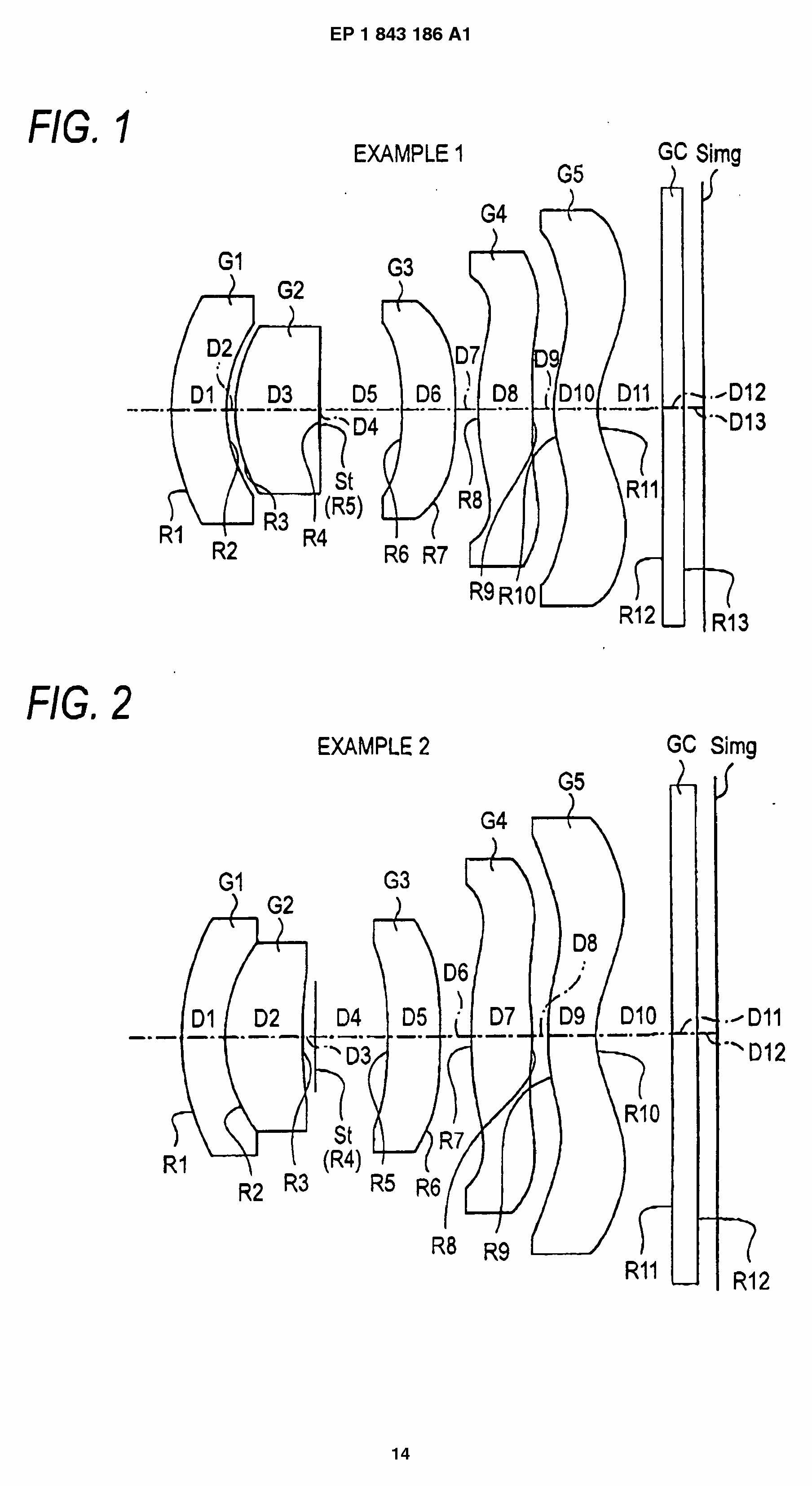
This place covers:
Illustrative example of subject matter classified in this group:
This place covers:
Illustrative example of subject matter classified in this group:
(as a tag, double classification with the group for the respective element)
This place covers:
Illustrative example of subject matter classified in this group:
This place covers:
Illustrative example of subject matter classified in this group:
This place covers:
Illustrative example of subject matter classified in this group:
This place covers:
Illustrative example of subject matter classified in this group:
 (lenses 310 are deformed by exerting radial force on the lens bodies; other variable elements, diaphragm, LC-elements, etc.)
This place covers:
Illustrative example of subject matter classified in this group:
This place covers:
Illustrative example of subject matter classified in this group:
Attention is drawn to the following places, which may be of interest for search:
Lens arrays per se |
This place covers:
Illustrative example of subject matter classified in this group:
 Details covered by G02B 15/00 are to be classified there as well.
Attention is drawn to the following places, which may be of interest for search:
Zoom lenses per se |
This place covers:
Objectives designed to cover a very wide field of view not achievable by standard lens systems.
For example:
- Very wide objectives, e.g. fisheye lenses, were the increase in coverage is done at the expense of distortion correction
- Reflecting optical systems
- Multiple lens systems providing an extended field coverage
Attention is drawn to the following places, which may be of interest for search:
optical sysyems for splitting a field on multiple detectors |
G02B 13/06 is also used to classify catadioptric optical systems providing a 360°overage
Rectilinear,e.g. non-distorting, wide angle objective are classified in G02B 13/04
In this place, the following terms or expressions are used with the meaning indicated:
Sky lens | Objective designed for full sky coverage, e.g. for an hemispheric field of view |
Attention is drawn to the following places, which may be of interest for search:
Diffusing elements in general |
This place covers:
Refractive optical objectives with means for varying the magnification, e.g. zoom lenses;
optical aspects thereof.
This place does not cover:
Anamorphotic objectives |
Attention is drawn to the following places, which may be of interest for search:
The mechanical aspects of zoom lenses (e.g. cam arrangements) are covered by | |
Simple miniaturized zoom lenses for mobile electronic devices | |
Catoptric systems having a variable magnification | |
Catadioptric systems having a variable magnification | |
Optical systems with movable elements for controlling the degree of correction of specific optical aberrations |
The range G02B 15/142 - G02B 15/1465 covers zoom objectives characterised by the number of groups and the corresponding refractive power sign sequence of the groups.
The refractive power of a group is the combined refractive power of the lenses constituting the group.
Groups are counted as consecutive sets of one or more lenses that remain fixed or move in unison, e.g., distances between lenses are constant within a group whereas distances between groups are variable during zooming.
Lens groups having two or more separate subgroups with a variable spacing are to be counted as multiple groups.
The symbols have the following systematic structure:
- G02B 15/14 ABCD (A-D being digits 0-9)
"A" is the number of groups
"B" defines the sign of the first group: 1 if the refractive power of the group is positive and 5 if negative
"CD" is a two-digit number with an eventual leading zero defining the remaining refractive power sequence on the basis of a decimal conversion of the plus (1) or minus (0) binary sequence of the positive groups, e.g. the sum of the values of the remaining positive groups, plus one (1):
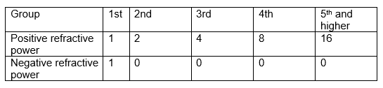
The first group has always the value of one (1) regardless of the sign of the first group, e.g. one (1) is added to the total, to avoid trailing zeros.
The sign of the first group is coded in position B.
Examples:
- A four group zoom arranged - + + - ("0110")
A = 4 groups
B = 5 (1st negative)
CD = 1*1+2*1+4*1+8*0 = 07
G02B 15/144507 { arranged - + + - }
- A five group zoom arranged + + + - + ("11101")
A = 5 groups
B = 1 (1st positive)
CD = 1*1+2*1+4*1+8*0+16*1 = 23
G02B 15/145123 { arranged + + + - + }
In patent documents, the word/expression in the first column is often used instead of the word/expression in the second column, which is used in the classification scheme of this place:
Lens group | A consecutive set of one or more lenses that remain fixed or move in unison. |
This place covers:
Systems with reflecting surfaces, with or without refracting elements, e.g. catoptric systems, catadioptric systems
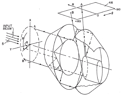
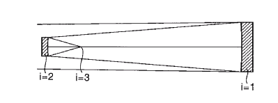
G02B 17/00, as the main group, is only for reflecting systems which do not fit into any of the sub-groups.
Example: a polar to rectangular coordinates converter:
Attention is drawn to the following places, which may be of interest for search:
Panomaric objectives | |
Scanning optics with mirrors | |
Optical derotators, e.g. rotating dove prisms |
G02B 17/00 in general should be seen as an optical design group.
The division with G02B 17/08 (catadioptric systems) is strict, the presence of any refracting element having power or asphere to correct the aberrations of the system qualifies the combination as catadioptric.
Solid systems (where the air is replaced by glass) are also catadioptric, even with zero power air interfaces.
Some application specific mirror systems relating to G02B are covered by groups outside this main group. However details might be classified in G02B 17/00. Examples are:
- G02B 13/06: Panoramic lenses takes precedence and should not be classified in G02B 17/06 or G02B 17/08.
- G02B 26/126: Optical F-theta scanner lenses with mirrors.
- G02B 21/04: Reflective microscope objective.
- G02B 27/642: Derotators
In this place, the following terms or expressions are used with the meaning indicated:
Zero power surface | a flat reflective or refractive surface without optical power, i.e. having no converging or diverging effect on light |
This place covers:
Arrays of reflective systems. This is essentially to mirror systems what lens arrays are for lenses. The class can be combined with other G02B 17/02, G02B 17/04, G02B 17/06, G02B 17/08 classes describing the optical design.
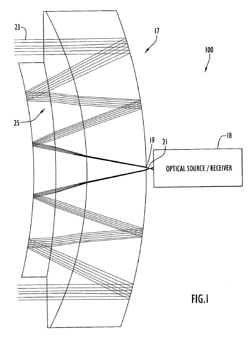
This place covers:
Systems comprising multiple reflections between at least two reflecting surfaces, e.g. cells, resonators. This subgroup covers both catadioptric and catoptric systems, as the number of documents is too small to justify a division between G02B 17/06 and G02B 17/08.
Attention is drawn to the following places, which may be of interest for search:
Multipass "cuvettes" in spectrophotometers | |
Laser cavities |
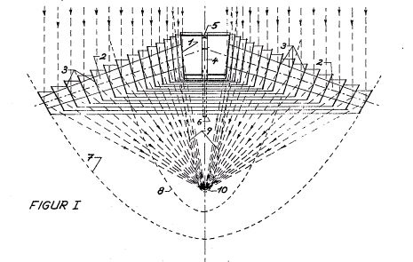
This place covers:
Systems in which the light is reflected on a plurality of parallel laminas (venetian blind lens, louvre mirror, TIR - total internal reflection lens). This subgroup covers both catadioptric and catoptric systems, as the number of documents is too small to justify a division between G02B 17/06 and G02B 17/08. Fresnel mirrors are in G02B 5/09.
This place covers:
Reflective systems specially adapted to form relays or chainable optical systems. Mainly unit magnification systems like Dyson optics or Offner relays.
This place covers:
Sequences of flat reflective (zero power) surfaces made of mirrors and prisms.
Attention is drawn to the following places, which may be of interest for search:
Sequences of flat reflective (zero power) surfaces using prisms only |
This place covers:
Essentially sequences of flat mirrors to extend a path length, e.g. in a flatbed scanner.
For extending an optical path length, e.g. delay lines
This place covers:
Image erecting and reversing systems, beam redirecting.
Static systems for changing the direction of a beam or pivoting an image
This place does not cover:
Prismatic systems with reflecting surfaces having static image erecting or reversing properties only | |
Movable reflecting elements for controlling the direction of light | |
optical derotators |
This place covers:
Prism sequences as far as the reflecting surfaces have no power. Powered prisms generally go in the catadioptric class G02B 17/08 (unless an image erecting effect is produced).
This place covers:
Image erecting and reversing systems, including classical erecting prisms. Similar to G02B 17/026, but with prisms only. Some overlap with G02B 5/04 and G02B 27/14.
The class might also be given for solid catadioptric systems that integrate an erecting function.
This place does not cover:
Movable or deformable reflecting elements for controlling the direction of light | |
Optical derotators |
This place covers:
Systems comprising mirrors only.
combinations of a single curved mirror (on or off axis) with any number of plane mirrors go into the group G02B 17/06. Single segmented mirrors are classified in G02B 5/09. Synthetic aperture systems G02B 27/58)
This place does not cover:
Mirror based non imaging systems |
Further details of subgroups
The subgroups G02B 17/0605, G02B 17/0626 and G02B 17/0647 relate to systems having 2 mirrors, 3 mirrors and more than 3 mirrors respectively, and are strictly imaging groups, including linear field imaging systems (scanner optics).
The structure of these groups, by way of example for G02B 17/0605 is the following:
- G02B 17/0605 On axis systems without a central aperture.
- G02B 17/061 On axis systems, with at least one central aperture.
- G02B 17/0615 Off-axis, unobscured, optical systems, the mirrors having a common optical axis.
- G02B 17/0621 Off-axis or unobscured optical systems, the mirrors without a common optical axis, e.g. the mirrors have tilts and decenters. This includes also so-called free-form surfaces without rotational symmetry.
The general rule is to count the number of optical surfaces relevant for the optical design process:
- An optical surface on which the beam is reflected twice counts as one mirror, however single mirror having multiple zones figured with different optical surfaces counts as two mirrors.
- Simple flat folding mirrors are normally not counted when they are not essential to the invention, e.g. not relevant in the lens design process, for example a folding mirror.
- Flat mirrors are counted when they are used to achieve a double reflexion on the same mirror, e.g. when a powered mirror surface is used twice. Flat reflecting surfaces in solid catadioptric systems count also.
- When several systems are chained together, e.g. a telescope and a relay, the subsystems are counted and classified individually.
This place covers:
On axis systems, without a central aperture.
This place does not cover:
Having non-imaging properties | |
With variable magnification or multiple imaging planes, including multispectral systems |
This place covers:
On axis systems, with at least one central aperture.
This place covers:
Off-axis, unobscured, optical systems, the mirrors having a common optical axis.
This place covers:
- Off-axis or unobscured optical systems, the mirrors without a common optical axis, e.g. the mirrors have tilts and decenters. This includes also so-called free-form surfaces without rotational symmetry.
This place covers:
Illustrative example of subject matter classified in this group:
This place does not cover:
Having non-imaging properties | |
With variable magnification or multiple imaging planes, including multispectral systems |
This place covers:
Illustrative example of subject matter classified in this group:
mirror 2 is actually two mirrors 1 and 3.
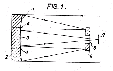
This place covers:
Illustrative example of subject matter classified in this group:
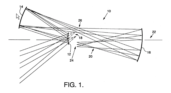
This place covers:
Illustrative example of subject matter classified in this group:
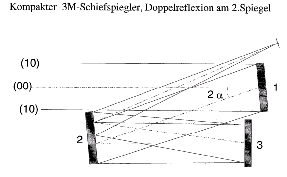
This place covers:
Illustrative examples of subject matter classified in this group:
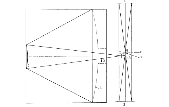
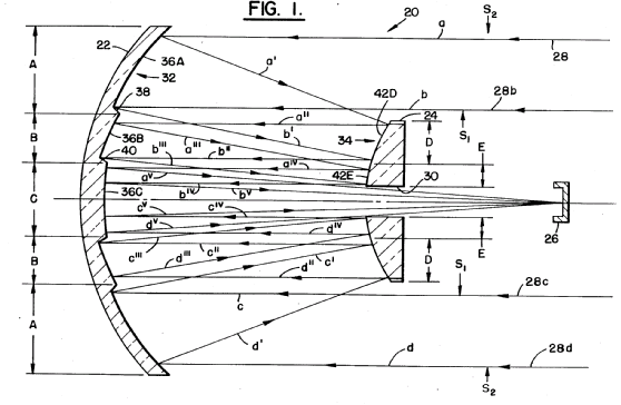
This place covers:
Illustrative example of subject matter classified in this group:
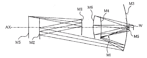
This place covers:
Illustrative example of subject matter classified in this group:
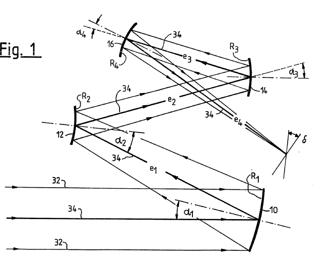
This place covers:
Non imaging systems.
Devices that are not emitter or receiver specific.
The group has been subdivided to cover systems disclosed as being used to illuminate a detector, or used in close conjunction with a light source (e.g. for LED illumination). Often the emitter/detector is an integral part of the device. Reflecting pipes are in G02B 27/0994 or G02B 6/00.
Example: a non-imaging system in the form of a rotating optical joint
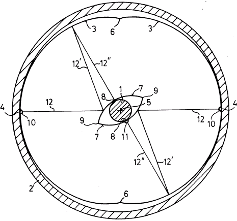
Further details of subgroups
G02B 17/0673 ..for light condensing (emitters)
G02B 17/0678 ... in a 360° plane or hemisphere
G02B 17/0684 ...for light collecting (receivers)
G02B 17/0689 ...in a 360° plane or hemisphere
This place covers:
Zoom mirror systems, but also multiple focus or multiple magnification systems, and systems having both large and small FOVs.
This place covers:
Catadioptric systems
This group is subdivided according to the same scheme as the systems of G02B 17/06.
In addition, subgroups have been added to cover the structure or function of the refractive element.
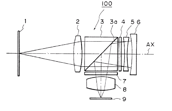
Further details of subgroups
G02B 17/0852: Field Corrector
Systems where a set of field lenses correct the aberrations of the mirrors.
The field corrector definition should be taken broadly to include systems where all lenses are located between the focal plane and the first mirror (starting from the FP).
Systems with field flattener lenses and pupil correctors get also this class when the design of the field corrector is detailed or discussed.
G02B 17/0884: Pupil Corrector
The pupil corrector having spherical surfaces, e.g. Maksutov or Houghton telescopes
G02B 17/0888: Pupil Corrector
The pupil corrector having an aspheric surface, e.g. Schmidt camera
G02B 17/0856 : Mangin mirror, i.e. a lens with a mirrored surface
G02B 17/086: Solid Catadioptric, e.g. comprising solid blocks
G02B 17/0864: Non imaging catadioptric
The G02B 17/0864 subgroup is subdivided according to the same scheme as the systems of G02B 17/0668.
G02B 17/0892: Specially adapted for UV (includes lithography objectives even without an explicit UV reference)
G02B 17/0896: With means for varying the magnification or providing a plurality of image planes from a single pupil (same rules as for G02B 17/0694)
The following table gives examples of patent documents classified in the subgroups of G02B 17/06 or G02B 17/08:
This place covers:
Illustrative example of subject matter classified in this group:
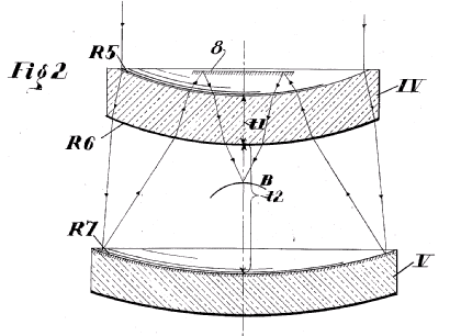
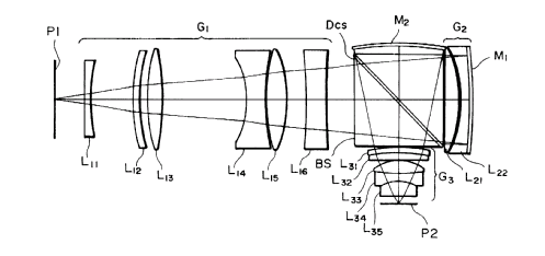
This place does not cover:
Having non-imaging properties | |
With variable magnification or multiple imaging planes, including multispectral systems |
This place covers:
Illustrative example of subject matter classified in this group:
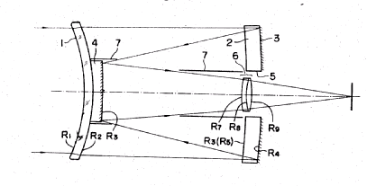
This place covers:
Illustrative example of subject matter classified in this group:
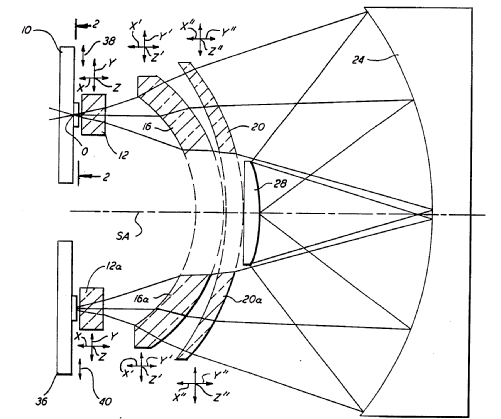
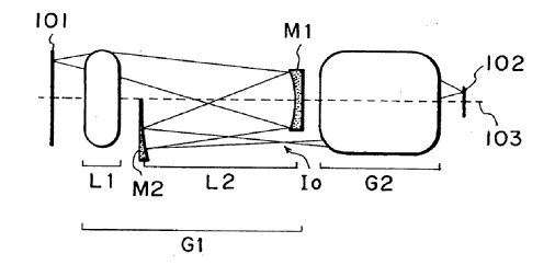
This place covers:
Illustrative example of subject matter classified in this group:
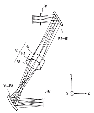
This place covers:
Illustrative example of subject matter classified in this group:
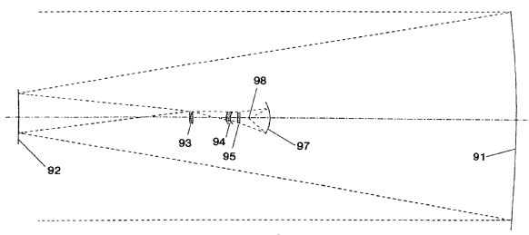
This place does not cover:
Having non-imaging properties | |
With variable magnification or multiple imaging planes, including multispectral systems |
This place covers:
Illustrative example of subject matter classified in this group:
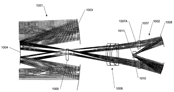
This place covers:
Illustrative example of subject matter classified in this group:
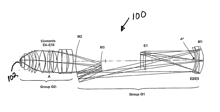
This place covers:
Illustrative example of subject matter classified in this group:
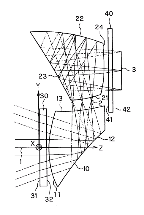
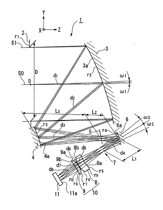
This place covers:
Illustrative example of subject matter classified in this group:
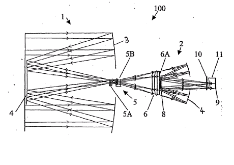
This place covers:
Illustrative example of subject matter classified in this group:
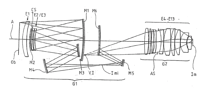
This place covers:
Illustrative example of subject matter classified in this group:
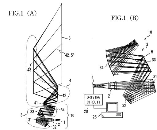
This place covers:
Illustrative example of subject matter classified in this group:
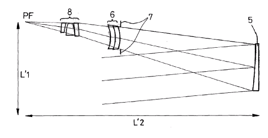
This place covers:
Illustrative example of subject matter classified in this group:
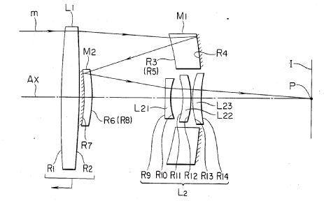
This place covers:
Illustrative example of subject matter classified in this group:
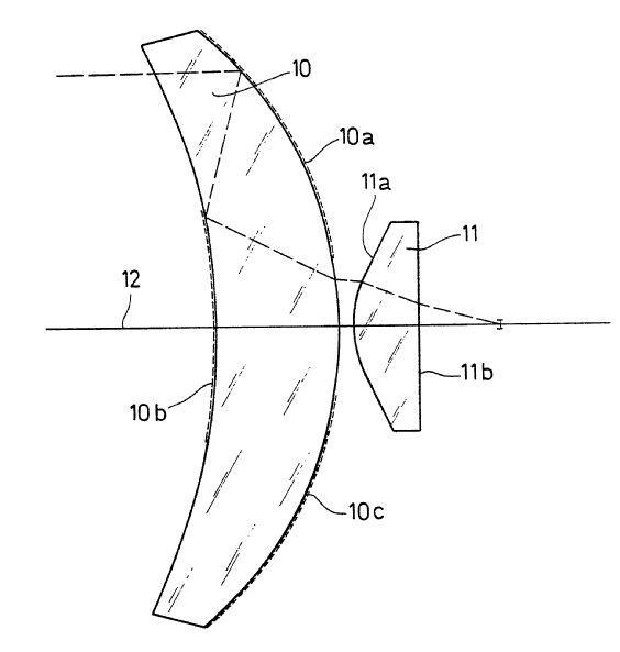
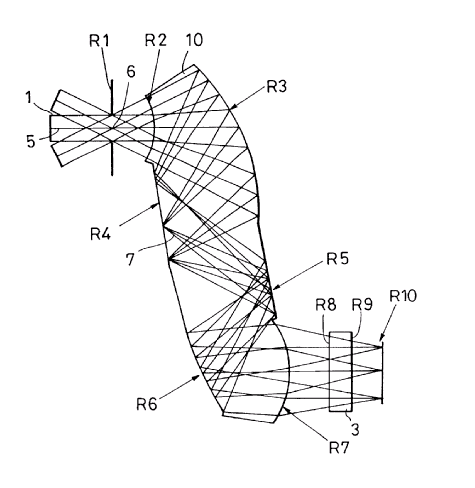
This place covers:
Illustrative example of subject matter classified in this group:
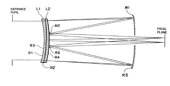
This place covers:
Illustrative example of subject matter classified in this group:
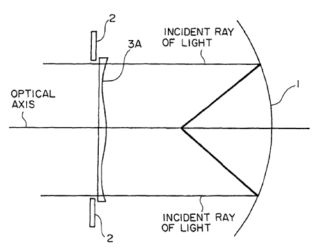
This place covers:
Optical condensers, light collectors and similar non-imaging optics.
This place does not cover:
Illumination arrangement in microscopes |
Attention is drawn to the following places, which may be of interest for search:
Lighting | |
Solar heat collectors | |
Optical elements combined with semiconductor receivers | |
Optical elements combined with semiconductor emitters |
Concerning optical arrangements for illumination from LEDs, the practice is to classify in G02B 19/0061 (or G02B 19/0066 for LED arrays) and in one or more other classes under G02B 19/00 according to the optical means employed. In particular:
- Arrangements involving refractive surfaces only, at least one surface having optical power, and adapted for a single LED are classified in G02B 19/0061 and in G02B 19/0014. For example:
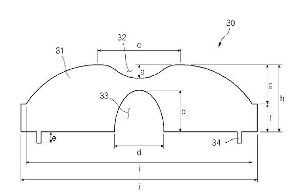
- Arrangements involving reflective surfaces only, at least one surface having optical power, and adapted for a single LED are classified in G02B 19/0061 and in G02B 19/0023.
- Arrangements involving reflective and refractive surfaces adapted for a single LED are classified in G02B 19/0061 and in G02B 19/0028. For example:
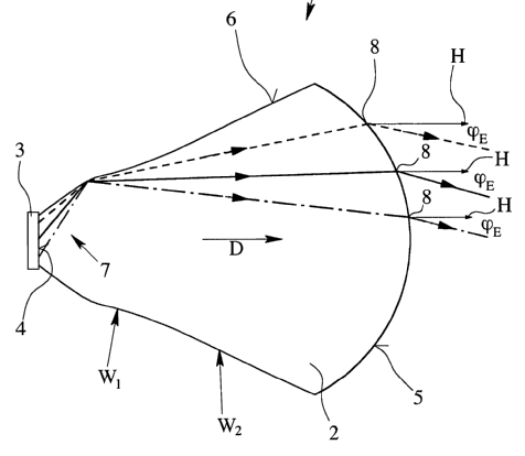
In the above examples, the classification G02B 19/0071 is additionally given in the case of adaptation to illuminate a complete hemisphere or a plane extending 360° around the source. For example, the following arrangement would be classified in G02B 19/0061, G02B 19/0028 and G02B 19/0071:
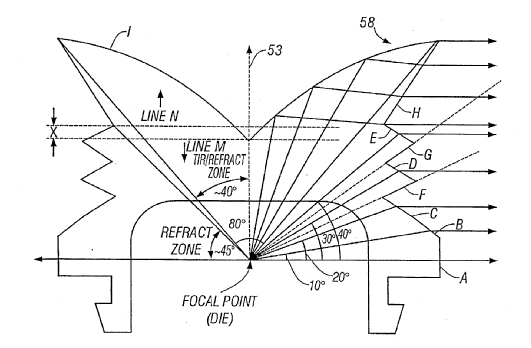
This place covers:
Optical microscopes including conventional microscopes, as well as laser scanning microscopes, confocal microscopes, fluorescence microscopes, video microscopes or optical aspects of surgical microscopes.
Examples of places where the subject matter of this place is covered when specially adapted, used for a particular purpose, or incorporated in a larger system:
Attention is drawn to the following places, which may be of interest for search:
Eyepieces | |
Polarising systems | |
Medical aspects of surgical microscopes | |
Microtomes | |
Scanning probe techniques or apparatus | |
Electron microscopes |
Non-confocal fluorescence microscopes, including visible and infrared ones, are classified in G02B 21/16
Attention is drawn to the following places, which may be of interest for search:
Preparing specimens for investigation | |
Means for supporting the objects or the materials to be analysed in electron microscopes |
This place covers:
- Telescopes, e.g. binoculars;
- Periscopes;
- Instruments for viewing the inside of hollow bodies e.g. endoscopes
Examples of places where the subject matter of this place is covered when specially adapted, used for a particular purpose, or incorporated in a larger system:
Attention is drawn to the following places, which may be of interest for search:
Objectives | |
Eyepieces | |
Non-optical aspects of weapon aiming or sighting devices |
Attention is drawn to the following places, which may be of interest for search:
Collimators in general | |
Graticules |
Attention is drawn to the following places, which may be of interest for search:
Objectives for image conversion or intensification | |
Electrical image converters with optical input and optical output |
Attention is drawn to the following places, which may be of interest for search:
Cases or receptacles in general |
This place covers:
Eyepieces (e.g. for microscopes or telescopes); Magnifying glasses
Attention is drawn to the following places, which may be of interest for search:
Simple lenses | |
Viewfinders for photographic apparatus |
This place covers:
Optical devices or arrangements using movable or deformable optical elements for controlling the intensity, colour, phase, polarisation or direction of light, e.g. switching, gating, modulating
Optical devices or arrangements the optical operation of which involves changing the optical properties of the material used by an applied field or force G02F 1/00
This place does not cover:
Devices or arrangements, the optical operation of which is modified by changing the optical properties of the medium of the devices or arrangements |
Examples of places where the subject matter of this place is covered when specially adapted, used for a particular purpose, or incorporated in a larger system:
Measuring characteristic of light, spectroscopy |
Attention is drawn to the following places, which may be of interest for search:
Mechanically operable parts of lighting devices for the control of light order | |
Control of light in general | |
Control of light sources |
In this place, the following terms or expressions are used with the meaning indicated:
Gyricon | The term gyricon refers to a type of electronic paper in the form of a thin layer of transparent plastic in which millions of small "bichromal" beads (i.e. with hemispheres of two contrasting colors) are randomly dispersed. When a voltage is applied, the beads rotate to present one colored side to the viewer, allowing images such as text and pictures to be displayed. |
Control | When referred to light or optical elements, systems or apparatus, covers affecting or directing one or more of the following properties of light: intensity; colour; phase; frequency or wavelength; polarisation; direction and one or more of the following optical operations: gating; switching or deflecting; modulation. |
This place covers:
Systems providing spectral filtering by an adjustable, e.g. variable spacing, optical cavity.
Adjustable Fabry-Perot devices in spectroscopy applications, e.g. as monochromators or for spectral analysis are classified in G01J 3/26. A further classification in G02B 26/001 is optional.
This place covers:
All documents describing rotating particle displays ("gyricons" etc.) are to be classified in G02B 26/026, for example:
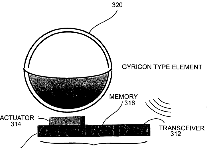
However, electrophoretic displays (involving particles moving linearly under the influence of an electric field) are classified in G02F 1/167.
Control of the intensity of light based on variable absorption of orientable dipolar particles is classified in G02F 1/172.
This place does not cover:
Displays based on electrophoresis | |
Displays based on orientable dipolar particles |
This place covers:
G02B 26/0833 is directed to optical MEMS per se with a high emphasis on the optical properties of the devices and their interaction with other optical elements in the apparatus.
This place does not cover:
Deformable or flexible reflecting membrane devices |
Attention is drawn to the following places, which may be of interest for search:
Mictomechanical devices in general |
In patent documents, the following abbreviations are often used:
DLP | Digital Light Processing |
DMD | Digital Micromirror System |
MEMS | Microelectrical Mechanical System |
MOEMS | Microoptical Electro Mechanical System |
Examples of places where the subject matter of this place is covered when specially adapted, used for a particular purpose, or incorporated in a larger system:
For special places |
This place covers:
Other optical systems, for example, head-up displays, head-mounted displays, beam-shaping systems, beam-splitting or combining systems, systems for producing stereoscopic or three-dimensional effects, polarising systems, diffraction systems.
Attention is drawn to the following places, which may be of interest for search:
Showcases | |
Optical toys | |
Designs or pictures characterized by special light effects |
Further details of other subgroups of G02B 27/00, like G02B 27/10 through G02B 27/44, see the definition of G02B 27/01.
The following IPC group is not used for classification: G02B 27/18, see the relevant subclasses according to the projector type. The subclass G02B 27/20 is, however, used for laser pointers or the like.
This place covers:
Devices for superimposing a synthetic image on a background scene by projection of a synthetic image on a background scene on a partially transparent surface:
- head mounted, e.g. pilot helmets
- non head mounted, e.g. windscreen of a car
- optical features
- mechanical features
- display position adjusting means not related to the information which is to be displayed
- sight systems
Examples of subject matter covered are:
Projection of flight or drive data on the windscreen of a plane or of a car (see for example US2011298693 paragraphs [0022],[0023], figure 1).
Vizor of pilots helmet with a partially transparent surface ("helmet mounted displays")
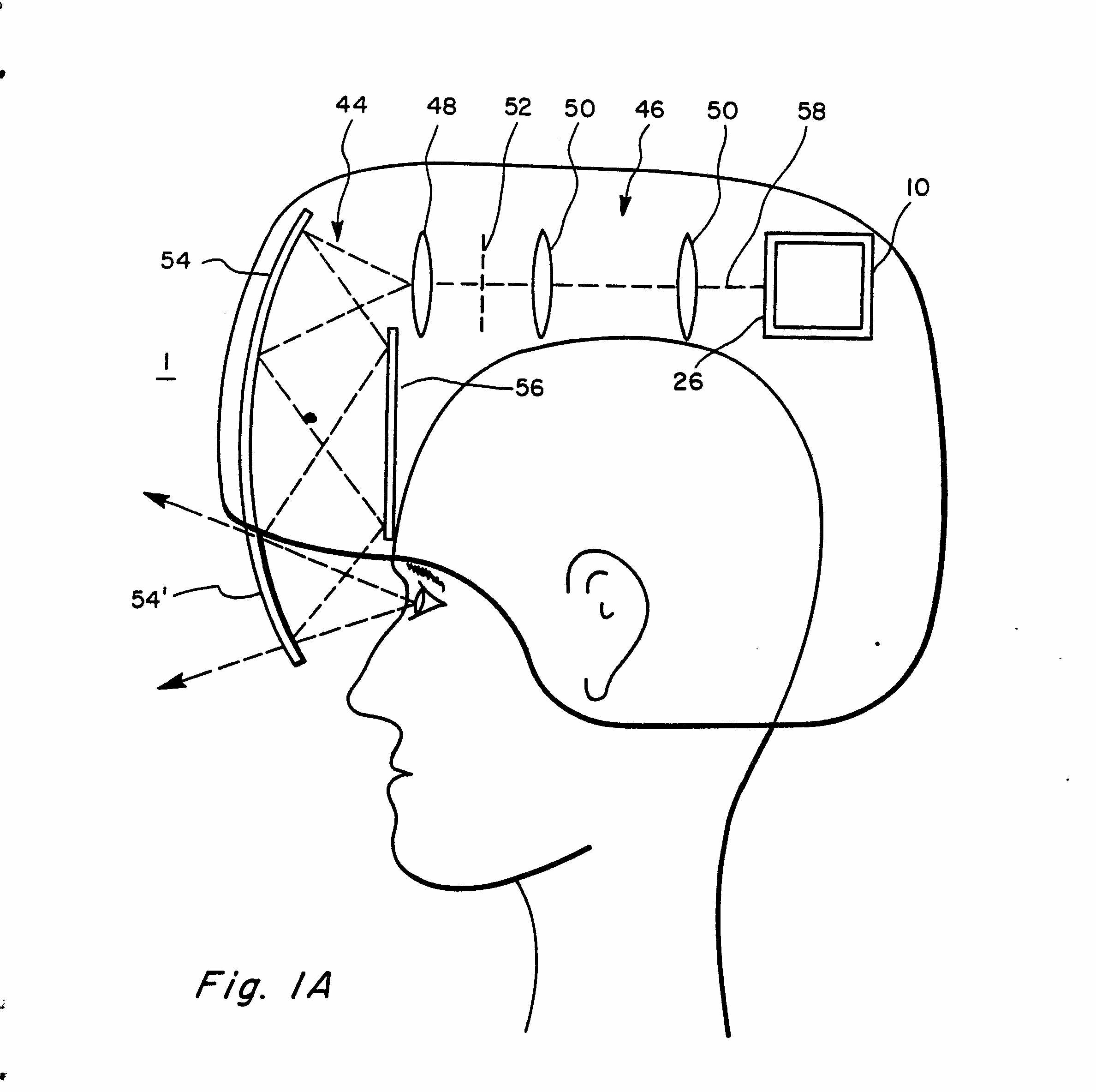
Further details covered by G02B 27/01 and not provided for in any of its subgroups is provided for in the subgroups of Indexing Codes G02B 27/01 and below. Classification is obligatory.
Further details of other subgroups of G02B 27/00
G02B 27/10: Beam splitting or combining systems
The scheme comprises subgroups covering specific structural technical solutions ("means") and a parallel set of subgroups covering the purposes of the devices, independently of the specific type of beamsplitter used.
The subgroup G02B 27/10 is intended for beamsplitting/combining systems which cannot be given any lower means subgroup in the scheme. In general, documents should be assigned at least one means subgroup and at least one purpose subgroup.
Purpose Subgroups: Examples
G02B 27/1006 for splitting or combining different wavelengths
For wavelength specific documents which are not covered by any lower entry.
All color imaging related documents are in the color sensing subgroup (G02B 27/1013) or in one of the color reproducing subgroups (G02B 27/102 and subgroups). These subgroups are not limited to RGB devices and cover also non visible or pseudocolor devices as long as the final image is intended for the human viewer.
For color or multispectral image sensors, e.g. splitting an image into monochromatic image components on respective sensors.
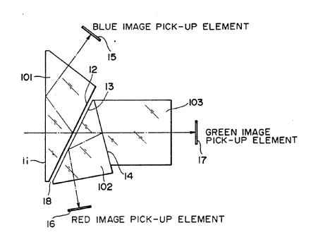
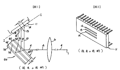
The devices must be imaging devices, including line scanning. Other spectral sensing devices belong to G02B 27/1006.
For generating a color image from monochromatic image signal sources.
Essentially covers color generating systems not specifically designed for a particular type of SLM, e.g. illumination systems combining multiple light sources
For use with reflective spatial light modulators
WO0038432
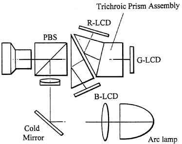
US2001000973
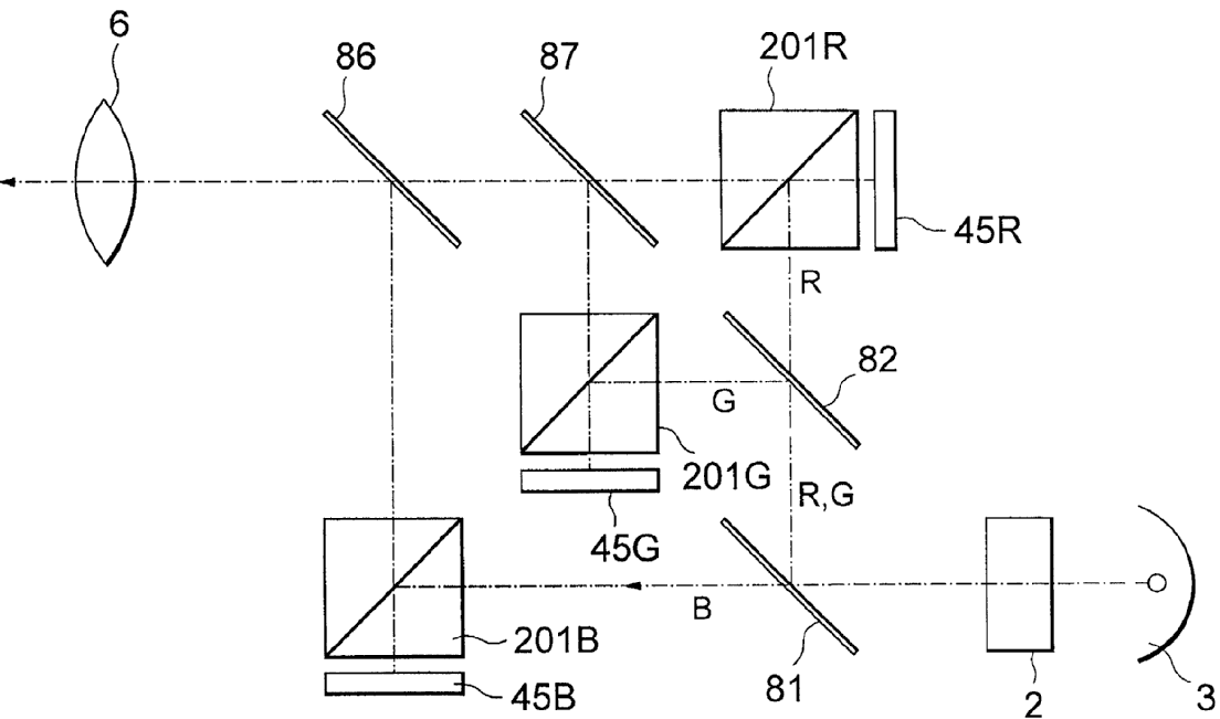
Having a single light modulator for all colour channels
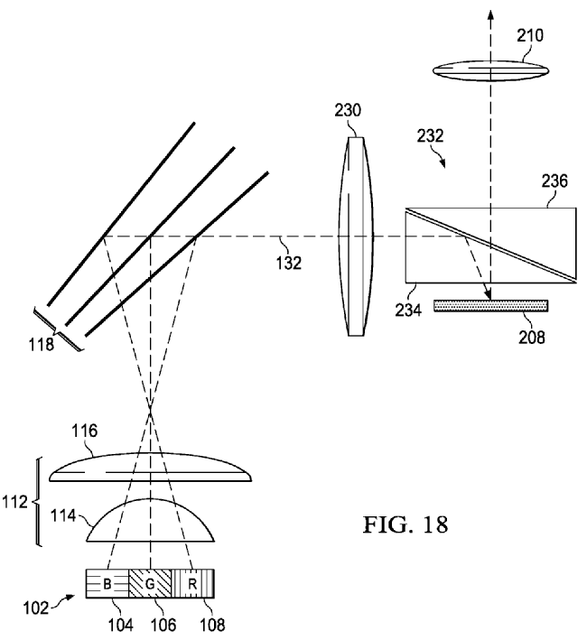
For use with scanning systems
Beams splitter/combiner arrangement for color scanning display arrangements
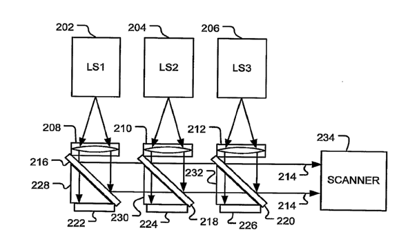
For use with transmissive spatial light modulators
The "classic" 3 LCD projector;
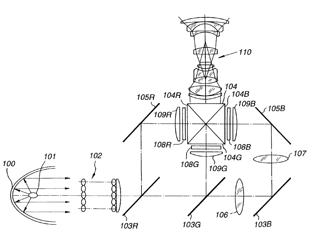
Using a single light modulator for all colour channels
for example time sequential led sources used with a single SLM, US2006196944
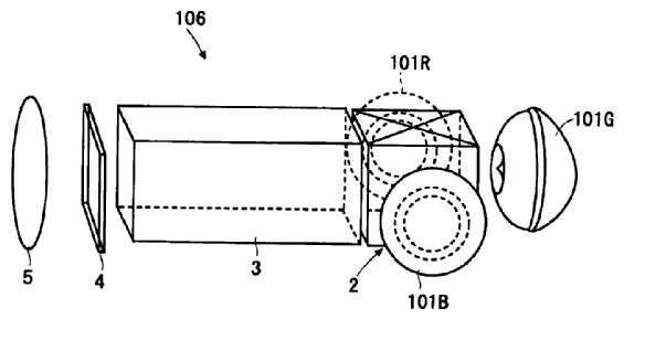
could be extended to light pipes: EP1003064
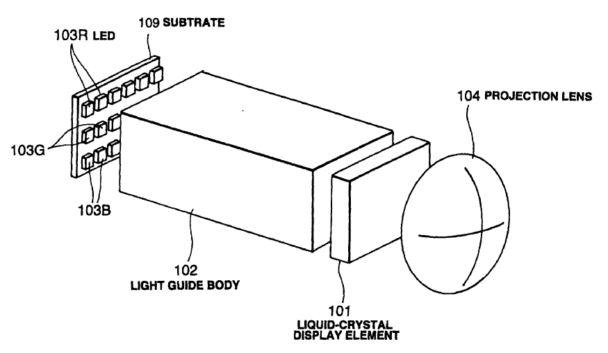
For splitting or combining a plurality of identical beams or images, e.g. image replication.
Quite a few documents deal with obtaining multiple identical copies of a beam. The numbers of beam should be four or more, color aspects are not relevant for this class.
US2006082890: construction laser
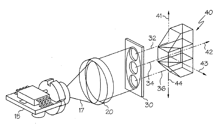
DE3502382: Laser beam replication.
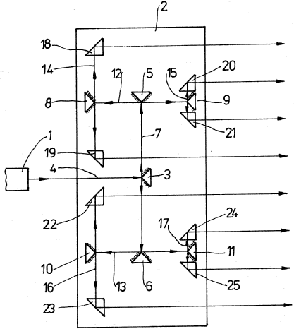
Characterized by manufacturing or alignment methods, e.g. assembly of cross dichroic cubes.
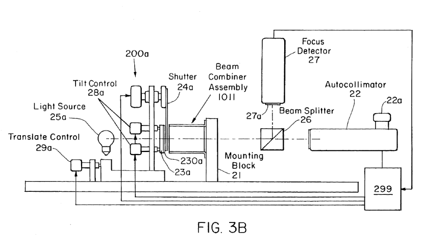 US5455678
 EP0947869
The subgroup is also relevant for mechanical aspects and devices where the alignment of the beams requires a particular construction (equivalent to G02B 7/00 for beamsplitters).
For enhancing image performance, e.g. resolution, pixel numbers, dual magnifications or dynamic range, by tiling, slicing or overlapping fields of view. Covers sensing or imaging devices where fields are either
- overlapping, e.g. dual resolution or pixel shifted systems, to increase the perceived resolution or
- abutted, save some border blending, for dividing or combining a larger field of view into or from subfields, e.g. detector or display tiling, image slicing.
Resolution should be taken in a broad sense, including high dynamic range systems.
GB2222892: high resolution CRT with a low resolution LCD
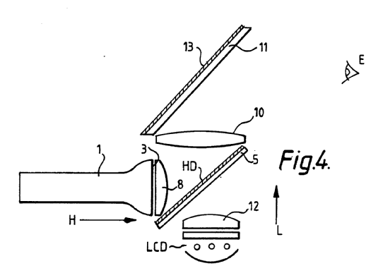
WO2008129552: "foveal" devices, narrow HD field with a large low resolution field
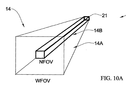
WO98/10402: mosaic displays
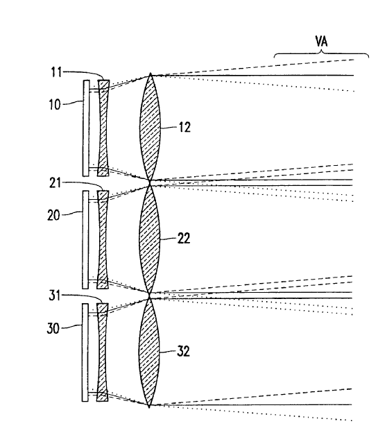
CA1073715: Slicing/dividing an image
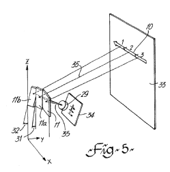
For sampling a portion of a beam or combining a small beam in a larger one, e.g. wherein the area ratio or power ratio of the divided beams significantly differs from unity, without spectral selectivity. Sampling devices for high power laser, laser beam insertion.
US4746205
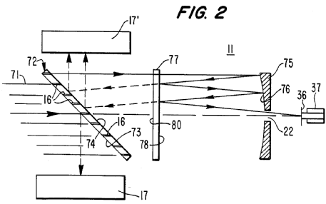
GB2027222
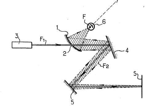
Means Subgroups: Examples
The decisive criterion is the physical principle leading to the splitting or combining, and not other aspects of the device. For example a cube beamsplitting prism operates by reflecting (part of) the beam, and hence operates by reflection, even though it also has refracting surfaces. Following the optical path, the relevant surface marks the boundary between the single beam and the multiple beams.
IPC classes G02B 27/12 and G02B 27/14 refer to "refraction only" or "reflection only" but some devices use both reflecting and refracting beamsplitting structure, e.g. US6400512 :
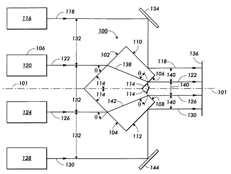
Applying strictly the IPC wording of the headers G02B 27/12 or G02B 27/14, such documents would not have their details classified in these subgroups. For the purpose of CPC classification, the limitation "only" should be disregarded. The above document would therefore be classified in G02B 27/12 (or a subgroup thereof) and G02B 27/14 (or a subgroup thereof).
Operating by diffraction only
Polychromatic diffractive combiners may be additionally classified in G02B 27/1013 or G02B 27/102.
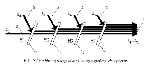
US2006109876
For use with monochromatic radiation only, e.g. devices for splitting a single laser source
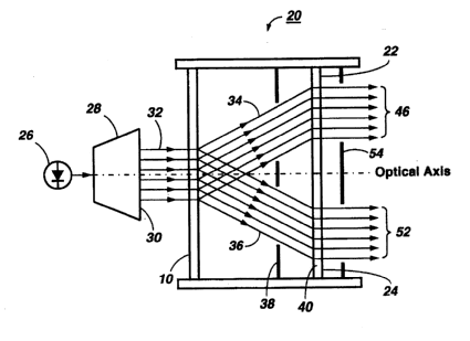
Since diffractive elements are intrinsically wavelength dependent, purely monochromatic devices represent special applications. G02B 27/1086 and G02B 27/1093 cover passive diffractive devices only
Operating by refraction only.
This subgroup comprises inter alia systems using birefringent materials for standard beamsplitting applications, for example not polarization relevant (polarization beamsplitters G02B 27/283).
The splitting element being a lens or a system of lenses, including arrays and surfaces with refractive power.
FR2889746: beam splitting takes place at 110a,110b
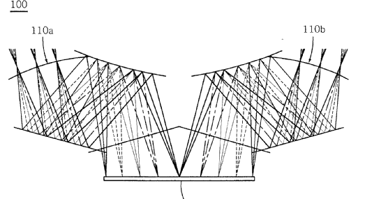
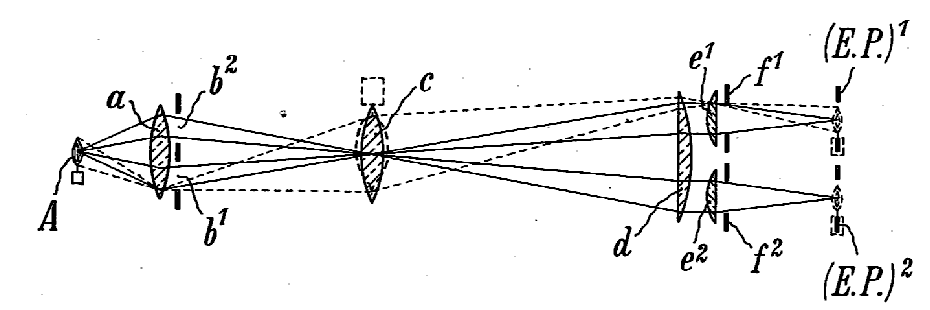
In G02B 27/123 the optical path should be branched. Fly eye beam shaping devices belong to G02B 27/0961, lens arrays per se in G02B 3/0006.
The splitting element being a prism or prismatic array, including systems based on total internal reflection.
The class covers both refracting deviating prisms, including spectral deviation and systems where the splitting/combining is achieved by total internal reflection without reflecting coatings:
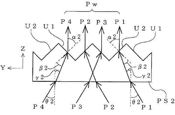
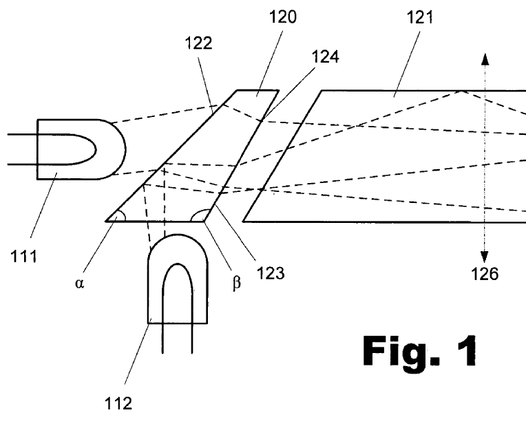
US2005174658
Operating by reflection only
For example a non conventional reflective beamsplitter as in US6266359:
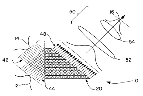
Using dichroic mirrors
For simple dichroic mirror arrangements transmitting a wavelength band and reflecting the other. G02B 27/1006 covers color splitting in general, and RGB image analysis or synthesis is covered by G02B 27/1013 or G02B 27/102 and lower.
Coating structure, e.g. thin films multilayers.
When the focus is the structure of the beam splitter coatings (thicknesses, materials, refractive indexes) including single thin metallic layers.
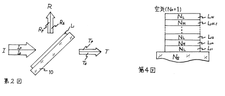
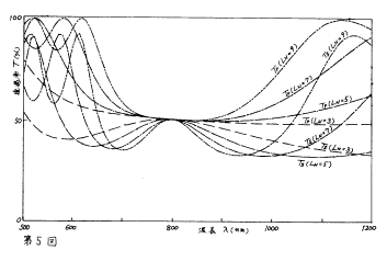
JP58208701: a polarisation independent multilayer semi-transparent coating.
Macroscopically faceted or segmented reflective surfaces
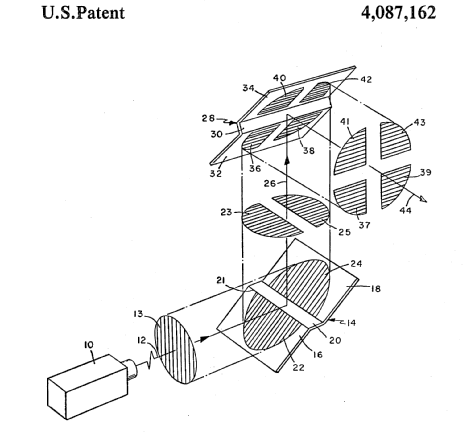
The segmentation here is macroscopic, compare with G02B 27/147.
Using partially transparent surfaces without spectral selectivity (G02B 27/147 takes precedence) for conventional half-mirrors.
US5198930:
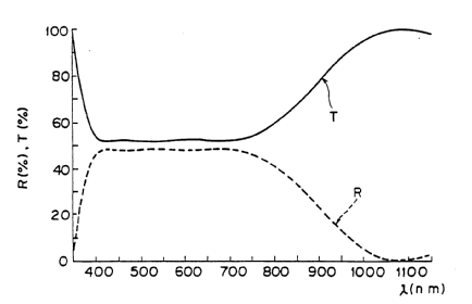
Having sequential partially reflecting surfaces
GB2153546
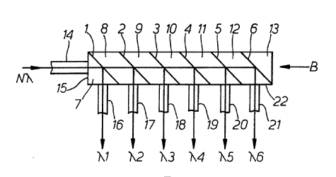
With a tree or branched structure
EP1626585
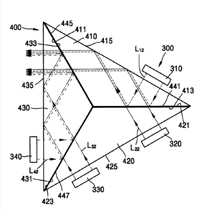
Using averaging effects by spatially variable reflectivity on a microscopic level, e.g. polka dots, chequered or discontinuous patterns, or rapidly moving surfaces (G02B 27/1086 takes precedence).
US4941012
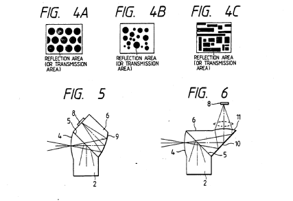
The subgroup also covers time averaging systems such as chopper mirrors rotating at high speed to emulate a beamsplitter.
JP52011894:
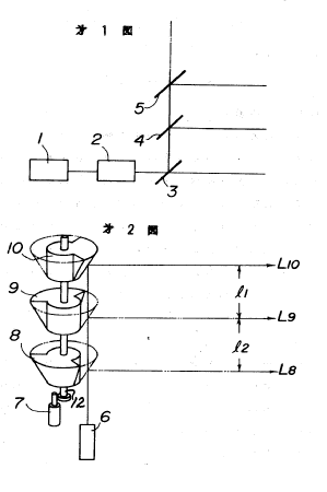
Devices incorporating crossed beamsplitting surfaces, e.g. cross-dichroic cubes or X-cubes. Not limited to three channels
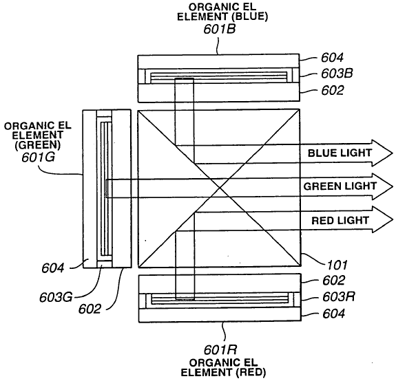
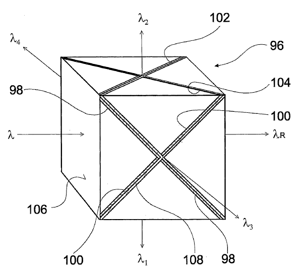
Including stacked surfaces having at least one double-pass partially reflecting surface
A special type but common type of beamsplitter where at least the front surface is crossed twice. Common for RGB angular separation, the last surface can be fully reflective.
US2009251783
Used as aids for focusing
Covers split prisms historically used to focus an image in reflex cameras and has almost no activity.
There are two groups for autostereoscopic systems (i.e. systems in which left and right images projected to the left and right eyes of an observer who is not required to view the images through special glasses optical systems placed adjacent to the eyes:
Autostereoscopic systems which comprise lenticular arrays or parallax barriers are classified in G02B 30/27.
Autostereoscopic displays which do not comprise lenticular arrays or parallax barriers, for example systems in which the left and right images are projected directly into the left and right eyes of the observer, are classified in G02B 30/26. An example of such a display is shown in the figure below
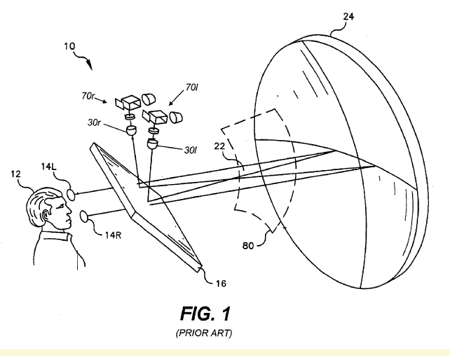
Concerns volumetric displays, i.e. in which an image is built up from image elements distributed over a three-dimensional volume. An example is US2007/0242324, in which visible fluorescence is excited at the crossing points of two scanned invisible lasers:
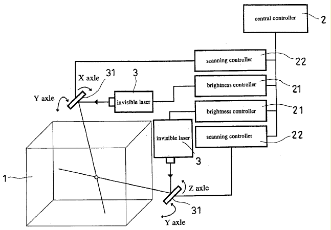
There are three subgroups:
The image being built up using a stack of two dimensional planes, e.g. US 2002/0130820:
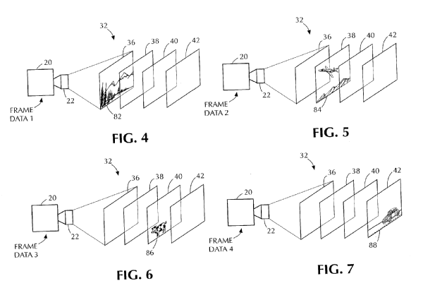
The volume being generated by a moving (vibrating or rotating) surface, e.g. US6115006:
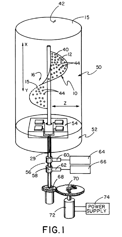
Projecting an aerial or floating image, typical examples of which would be WO02/061492:
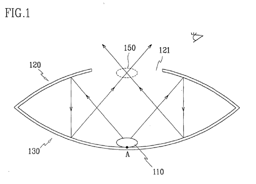
or WO95/19584
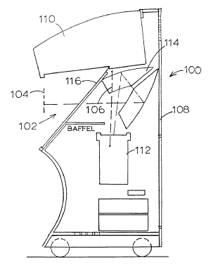
G02B 27/42: Diffraction optics
G02B 27/42 deals with systems comprising a DOE (diffractive optical element) having a significant interaction with another component of the optical system. If the document also discloses significant details about the diffractive element as such, it should be additionally classified in G02B 5/18. This subgroup contains documents in which the diffractive effect results from a purposeful design of a DOE. It does NOT include documents in which light is merely diffracted by an aperture, an edge or a particle. G02B 27/4266 is an exception to this rule. G02B 27/42 is essentially structured into two major groups:
.. imaging systems (G02B 27/4205 and lower)
.. non-imaging systems (G02B 27/4233 and lower).
Besides this major differentiation, there are three further divisions:
.. physical properties of the DOE:
polarization G02B 27/4261,
thermal G02B 27/4283,
spectral G02B 27/4288, G02B 27/4294
.. sequential DOEs G02B 27/4272 and G02B 27/4277
.. theory, models G02B 27/4266
In deciding whether a system is an imaging system or a non-imaging system, concepts such as image resolution or extended objects/images are strong hints towards imaging systems. On-axis point-like objects/images are pointers to non-imaging systems. It is important to note that G02B 27/4205 (and lower) and G02B 27/4233 (and lower) relate to the specific role played by the DOE in the system: a DOE within an imaging system, but merely deviating light for illumination purposes in a subsystem of the imaging system, is classified in G02B 27/4233 (or lower).
Specific rules
G02B 27/4233 (and lower) should preferably not contain documents which have a more specific class e.g. G02B 6/00 (optical fibers, waveguides), H01S (laser pulse compression), G01J (spectroscopy).
G02B 27/4238 should contain no document from the field of optical pick-up devices (these documents should be classified in G11B 7/1353).
G02B 27/425 should preferably contain no document about mask illumination in a lithographic apparatus (these documents should be classified in G03F 7/70158). This should not be confused with a DOE projecting an image of the mask onto a wafer, which is classified in G02B 27/4222).
G02B 27/4272 and G02B 27/4277 relate to plural diffractive elements positioned sequentially along the optical path means that the distance between sequential diffractive elements is large enough to ensure that each period of the subsequent grating receives diffracted light from several periods of the previous grating, i.e. far-field diffraction. For instance, DOEs which, at least in certain portions of the DOE are in direct contact or multilayered DOEs are normally not plural diffractive elements in the sense of G02B 27/4272 and G02B 27/4277.
When allocating G02B 27/42, consider also the relevance of the following classes in G02B relating to diffraction or gratings:
G02B 1/005 (photonic crystals)
G02B 1/118 (moth-eye anti-reflection structures)
G02B 5/0252 (diffusers using holographic or diffractive means)
G02B 5/18 (diffraction gratings per se)
G02B 5/203 (filters using holographic or diffractive means)
G02B 5/32 (holographic optical elements)
G02B 26/0808 (controlling direction of light)
G02B 26/106 (scanners using movable diffraction gratings)
G02B 27/0944 (beam shaping using diffractive optical elements)
G02B 27/1086 (beam splitting and combining by diffraction)
G02B 27/46 (spatial filters)
G02B 27/58 (superresolution, apodization)
G02B 27/60 (systems using moiré fringes)
Exemplary drawings for G02B 27/42
Diffraction optics, i.e. systems including a diffractive element being designed for providing a diffractive effect (G02B 27/60 takes precedence)
having a diffractive optical element [DOE] contributing to image formation, e.g. whereby modulation transfer function MTF or optical aberrations are relevant | |
correcting chromatic aberrations (G02B 27/0056, G02B 27/4222, G02B 27/4227 take precedence) | |
correcting geometrical aberrations | |
in projection exposure systems, e.g. photolithographic systems | |
in image scanning systems | |
having a diffractive element [DOE] contributing to a non-imaging application (diffusers having a diffractive element G02B 5/0252; filters having a diffractive element G02B 5/203; systems for controlling the direction of light having diffractive elements G02B 26/0808; scanning systems having diffractive elements G02B 26/106; beam shaping systems using diffractive optical elements G02B 27/0944; beam splitting or combining systems operating by diffraction G02B 27/1086 ) => consists of non-imaging systems whose application has no dedicated class B1 to B7 | |
in optical recording or readout devices (optical pick-up devices such as for CD, DVD or BD reader or recorder using diffraction optics G11B 7/1353 ) => comprises mostly older documents | |
in wavelength selecting devices (spectrometry G01J) | |
in illumination systems (mask illumination systems in photolithographic systems G03F 7/70158) | |
for alignment or positioning purposes (optical displacement encoding scales G01D 5/347) | |
having a diffractive element with major polarization dependent properties | |
Diffraction theory; Mathematical models => background on diffractive patterns; diffracted wave propagation; a real DOE is not necessarily present | |
having plural diffractive elements positioned sequentially along the optical path | |
• | |
having a diffractive element with major temperature dependent properties | |
having uniform diffraction efficiency over a large spectral bandwidth | |
in multispectral systems, e.g. UV and visible | |
Grating systems: NOT IN USE IN CPC(documents classified in G02B 27/42 and subgroups). |
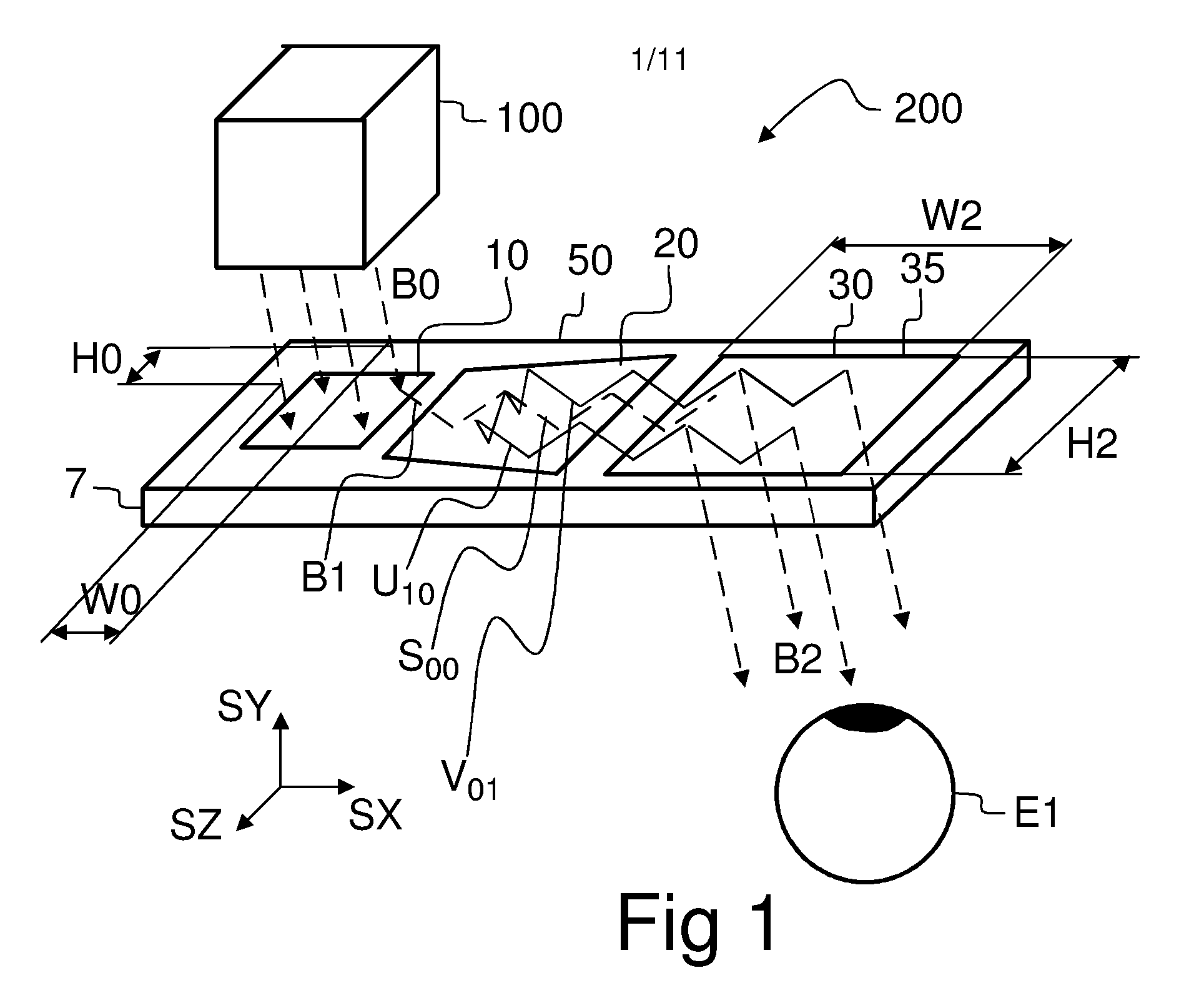
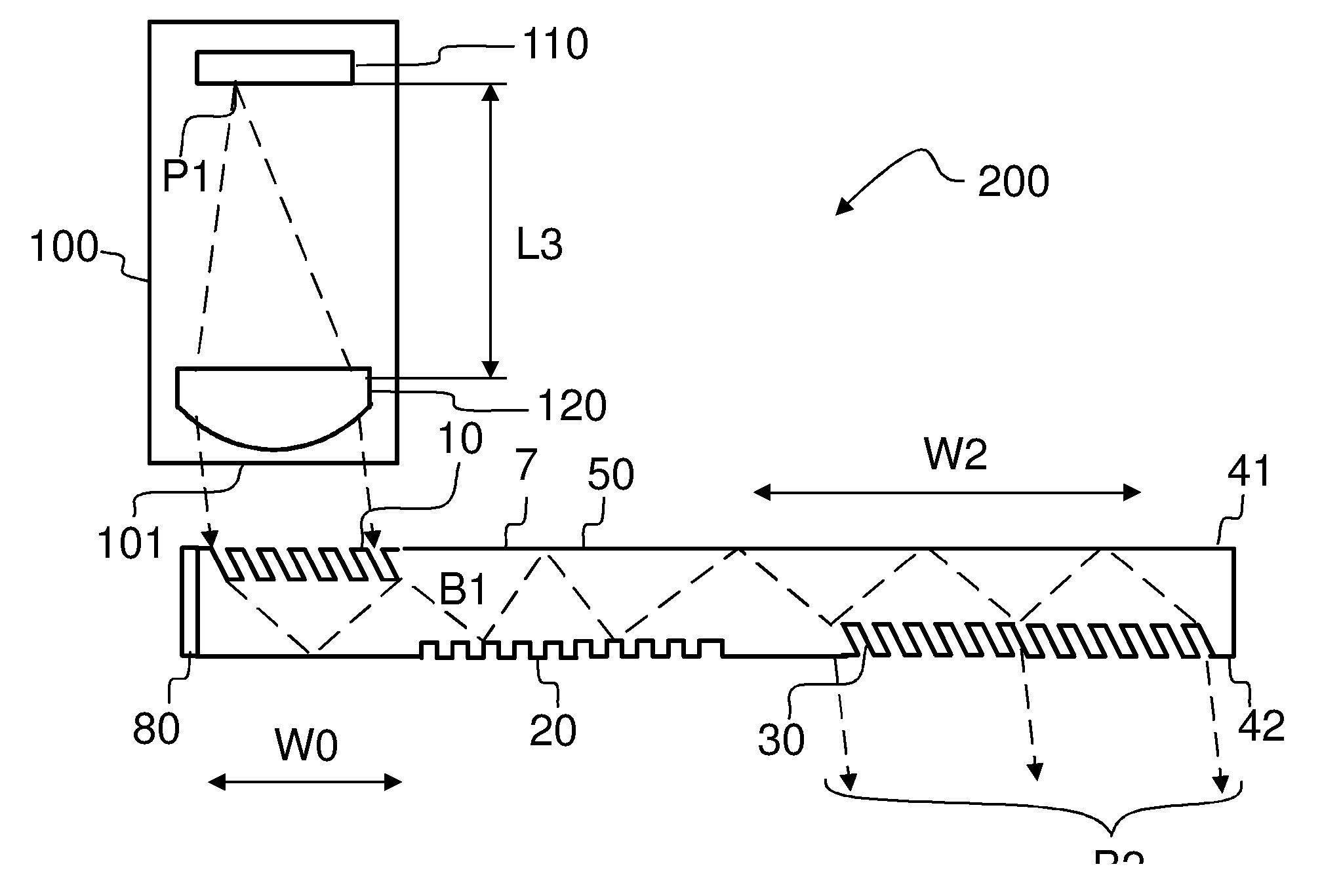
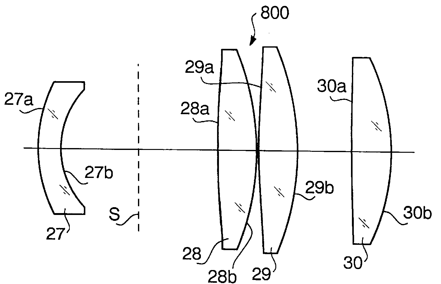
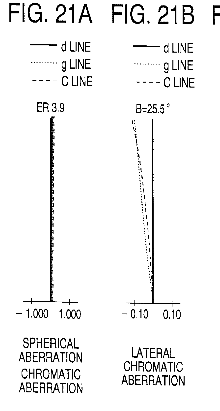
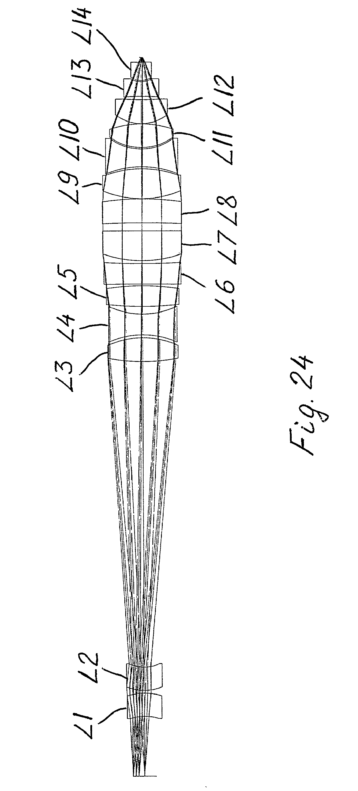
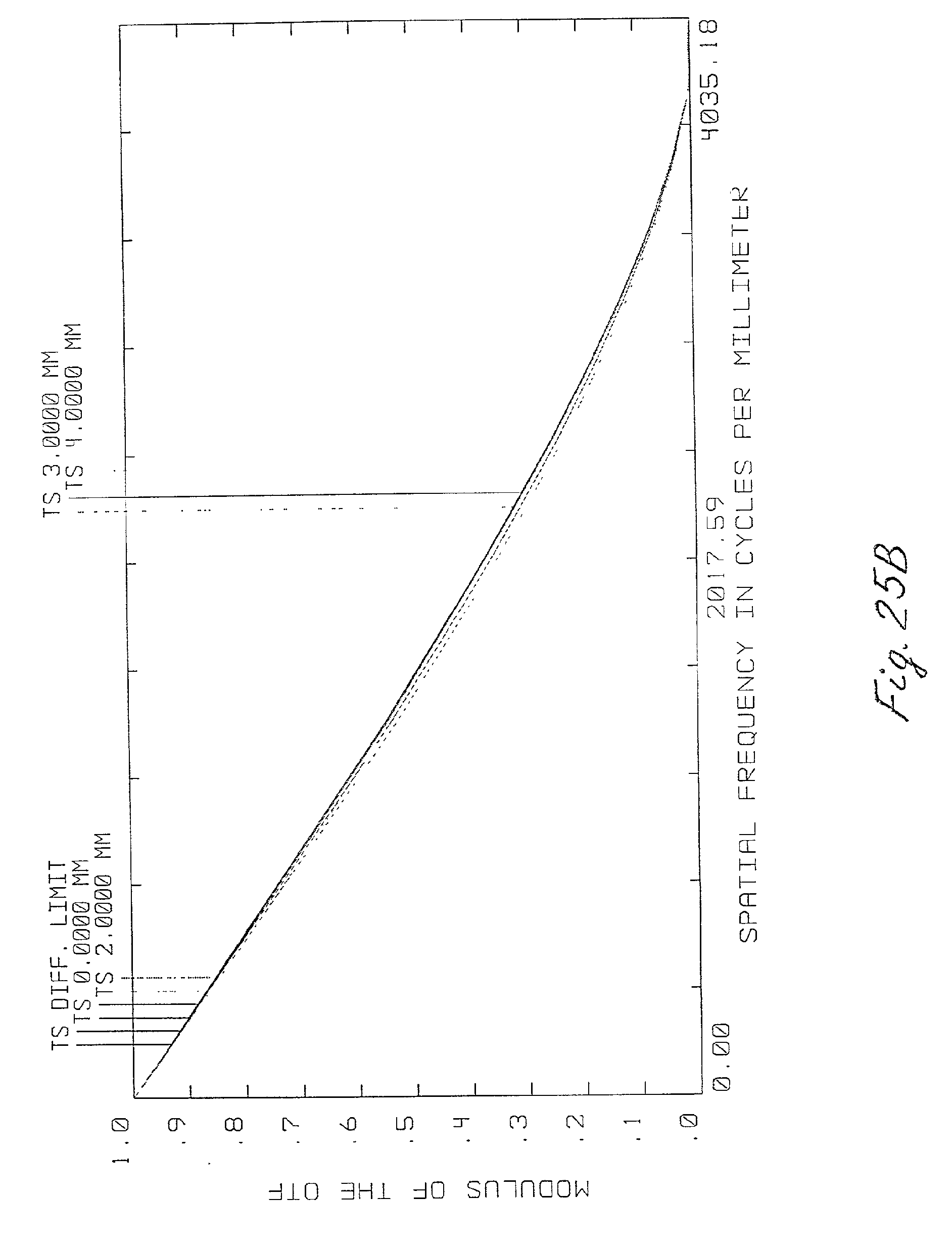
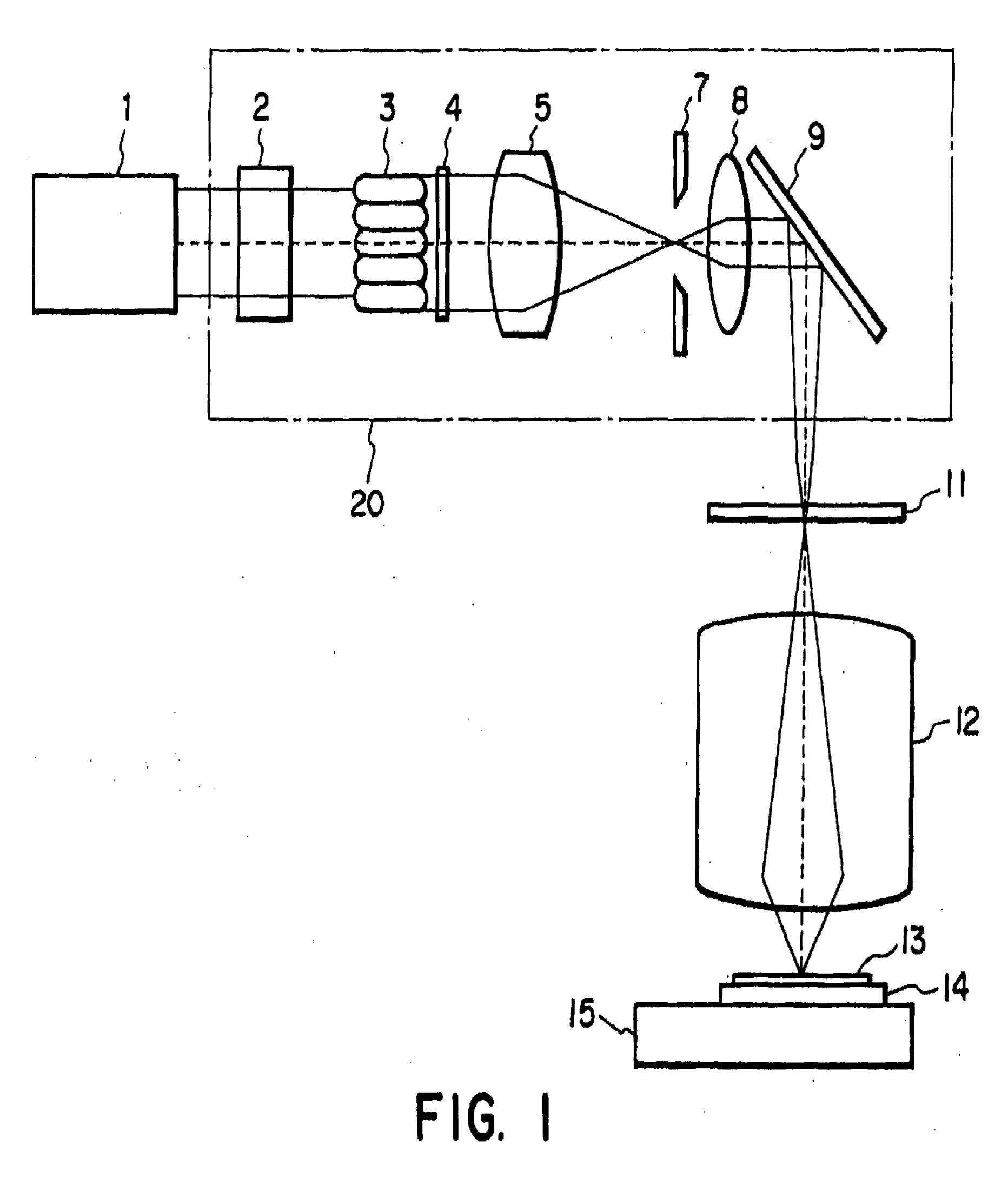
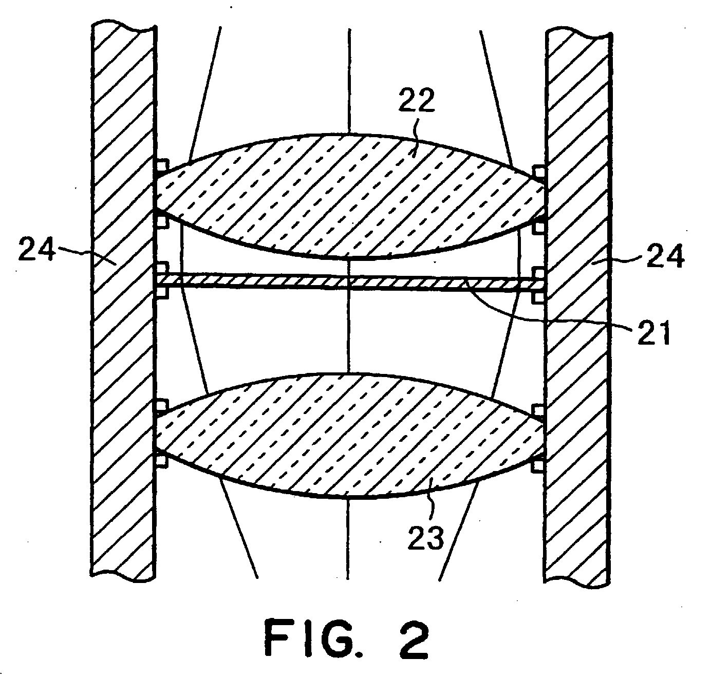
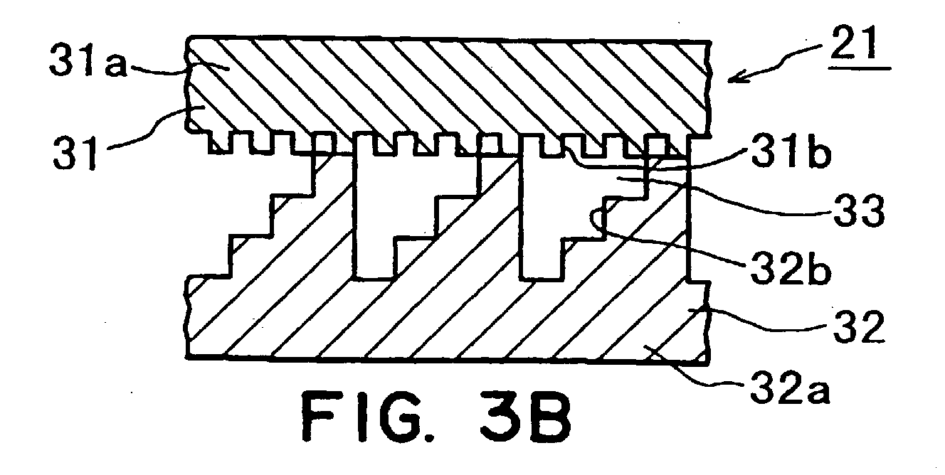
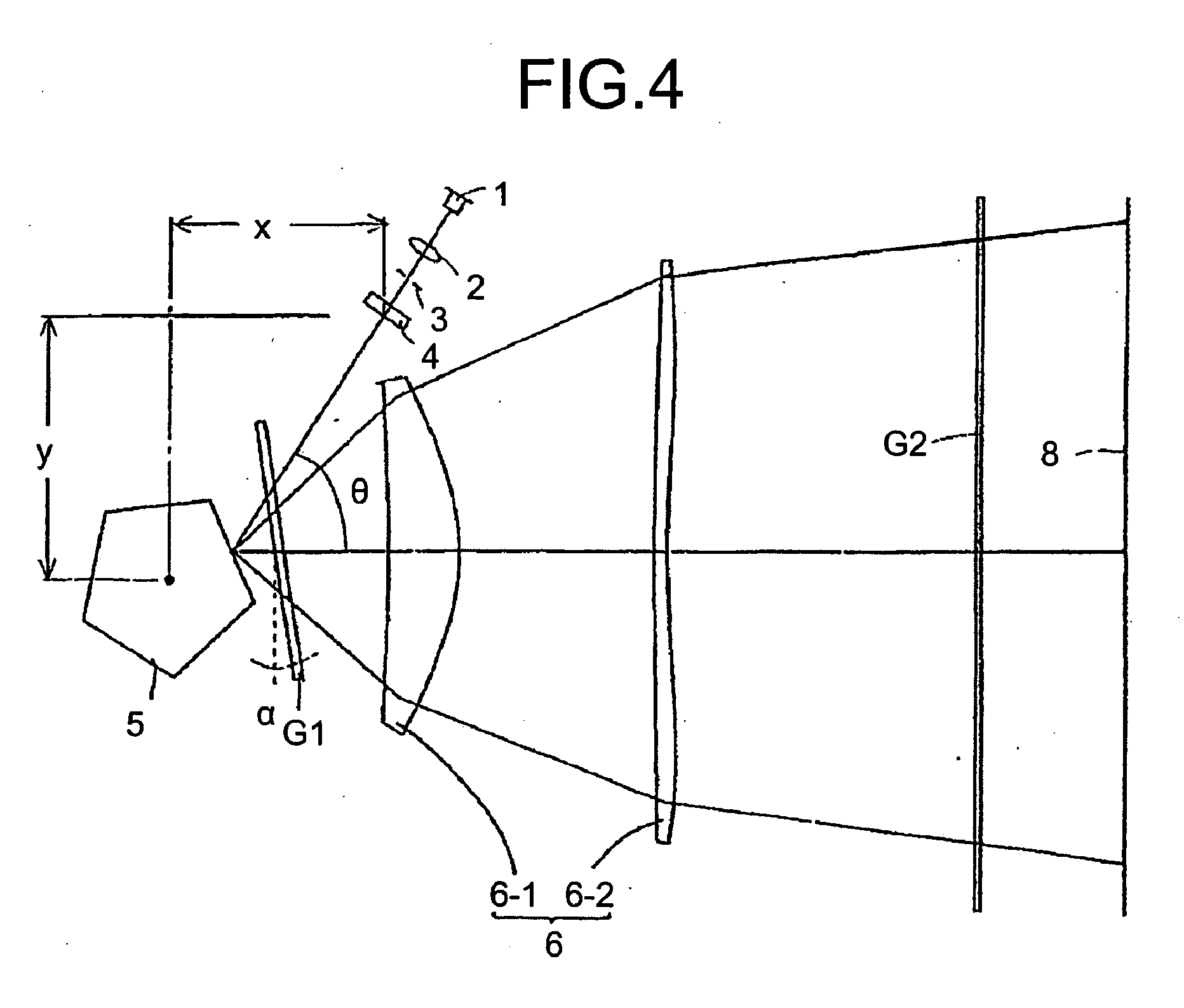
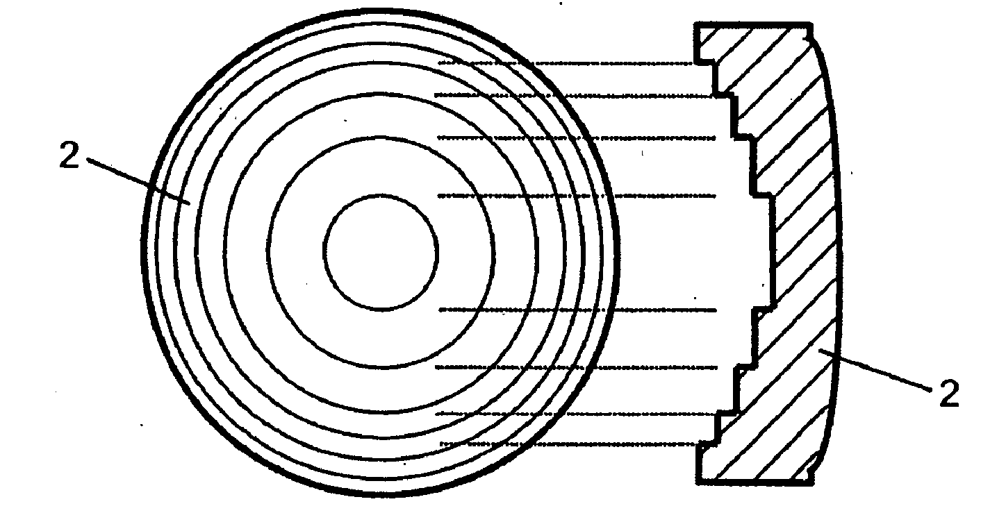
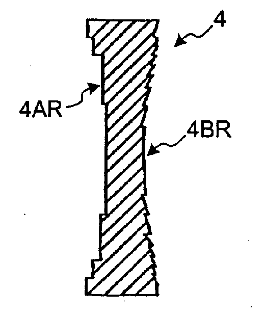
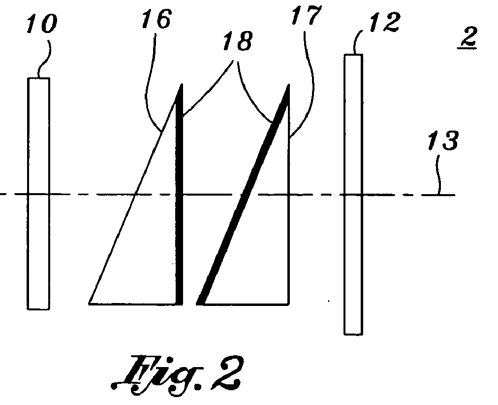
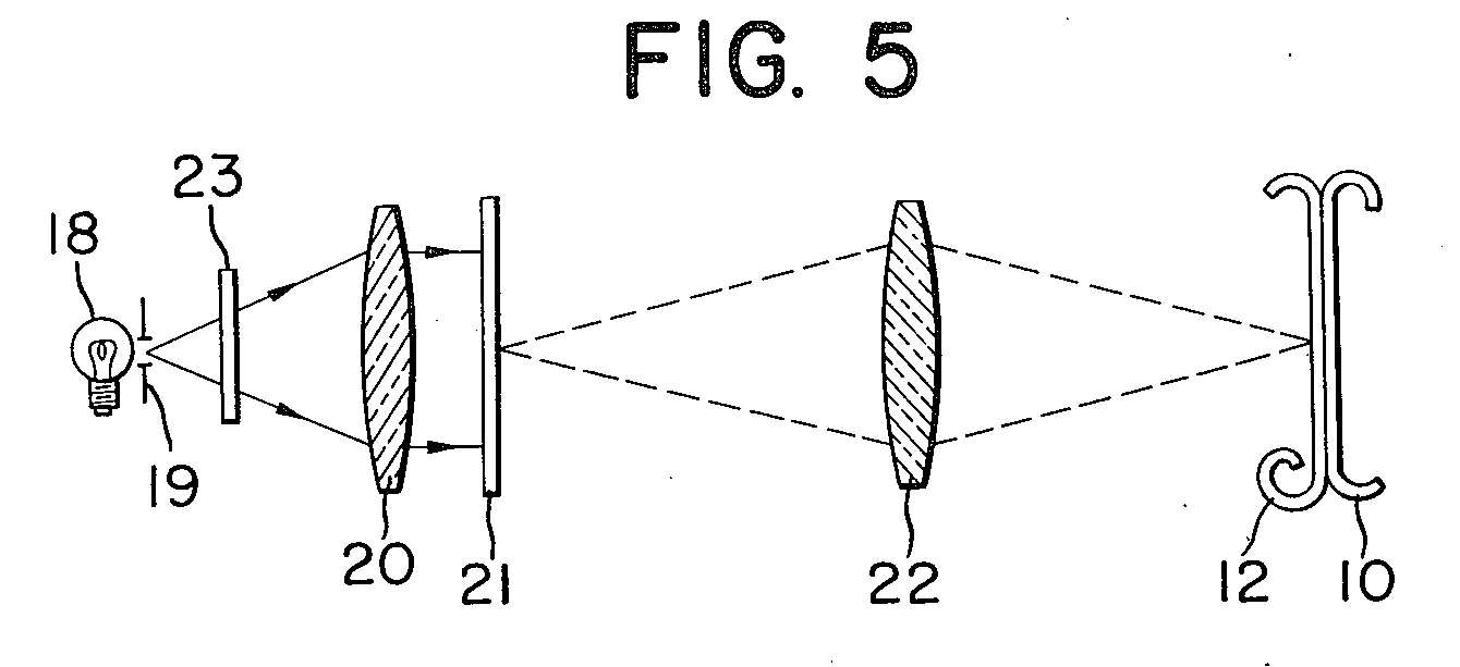
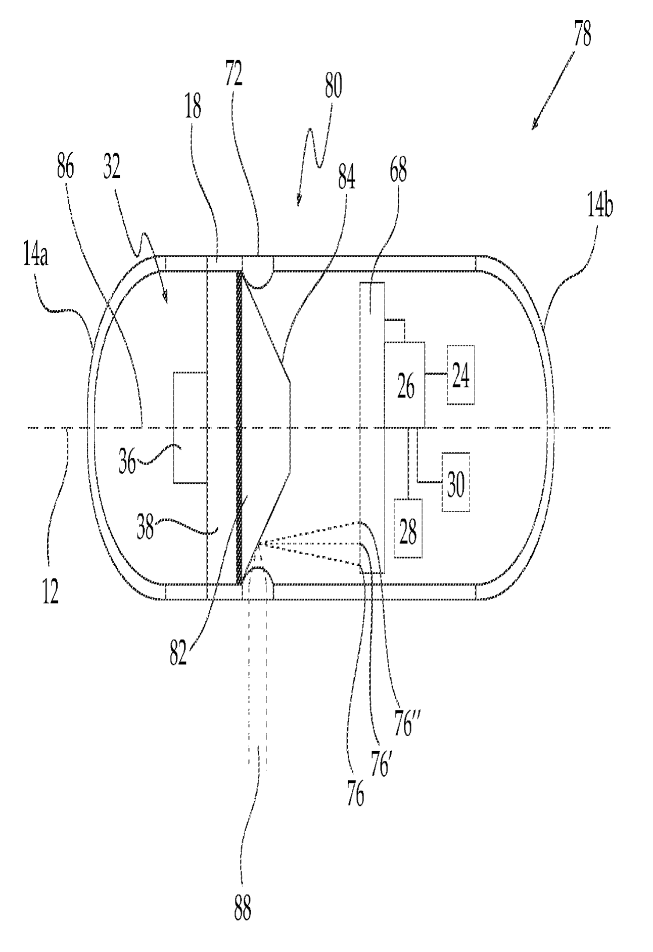
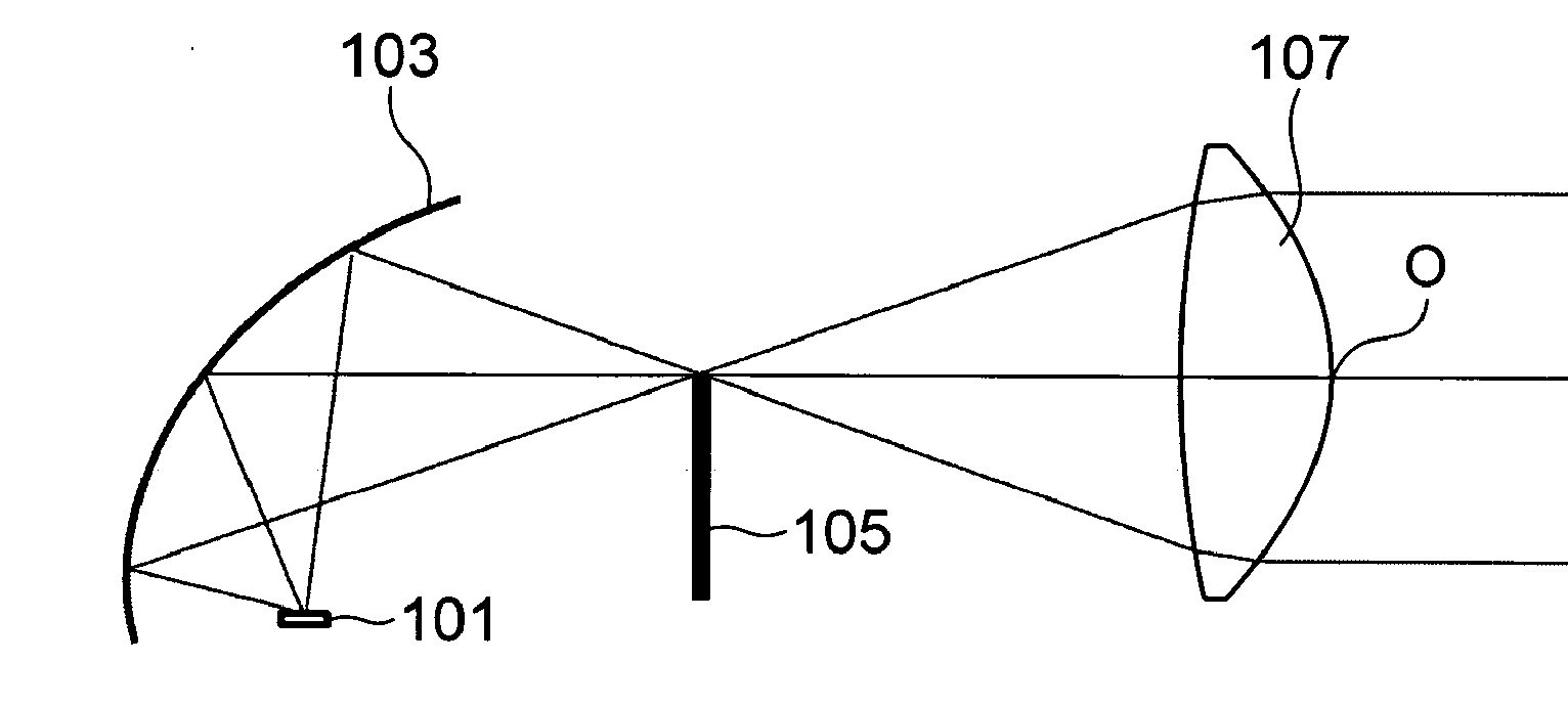
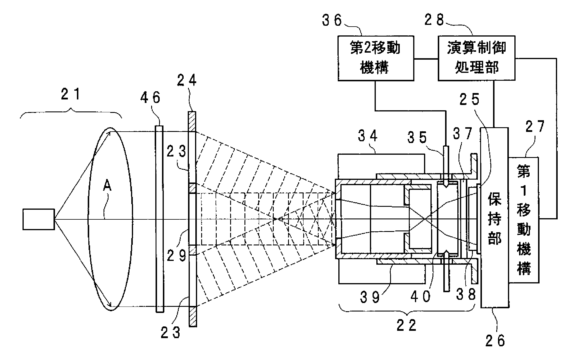
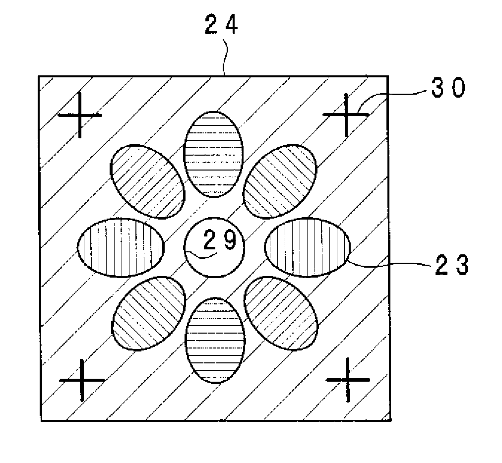
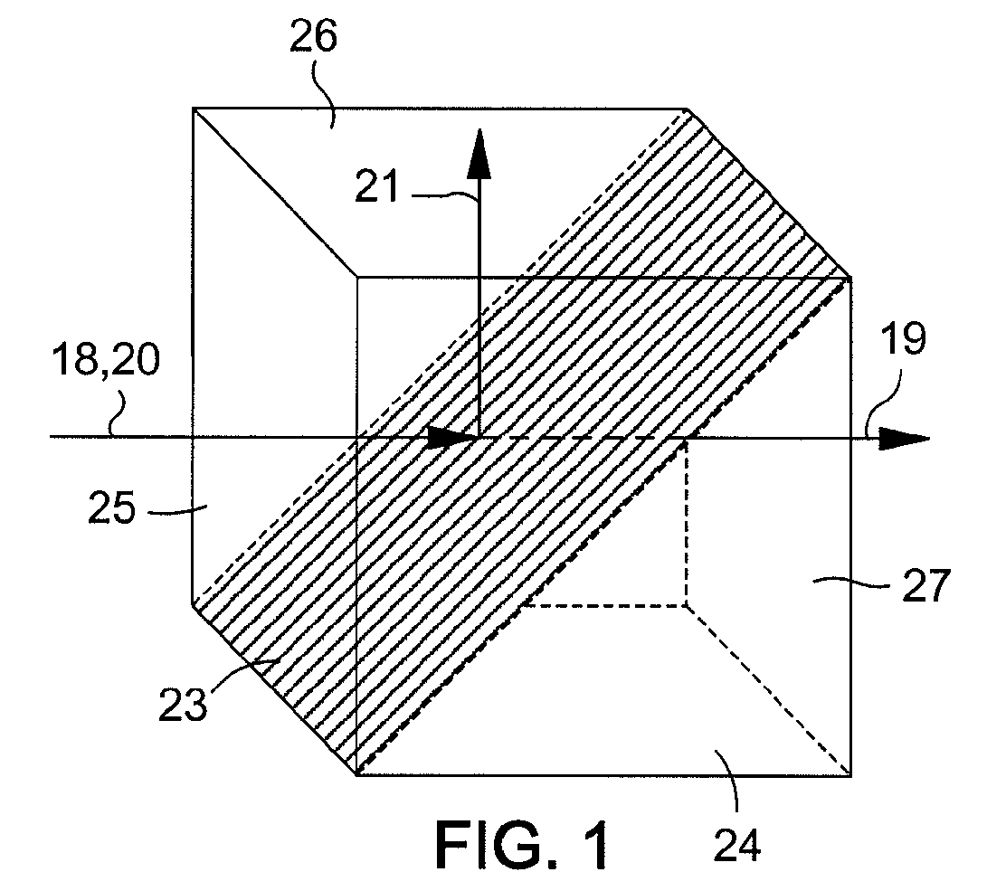
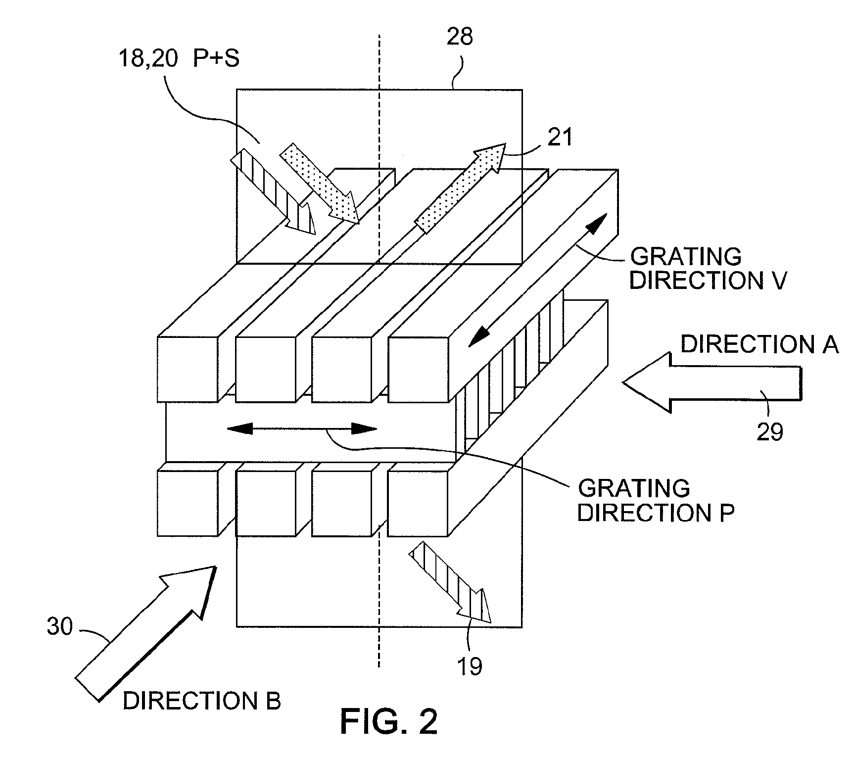
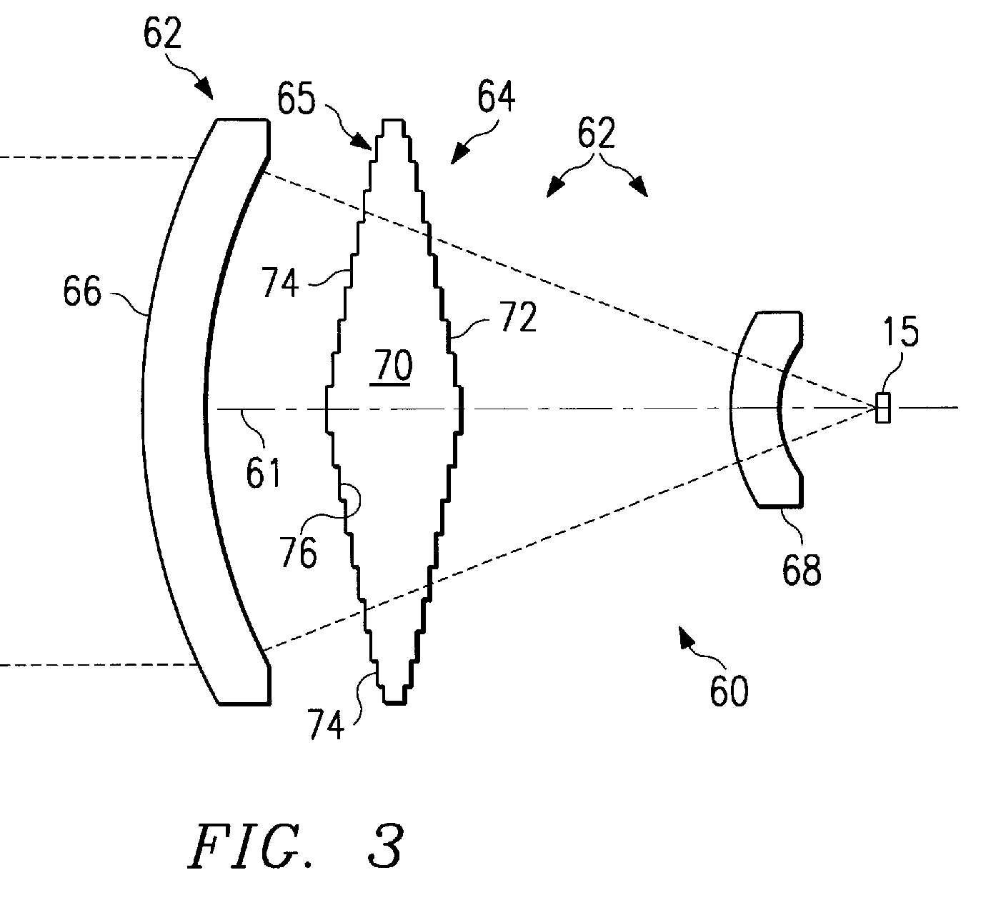
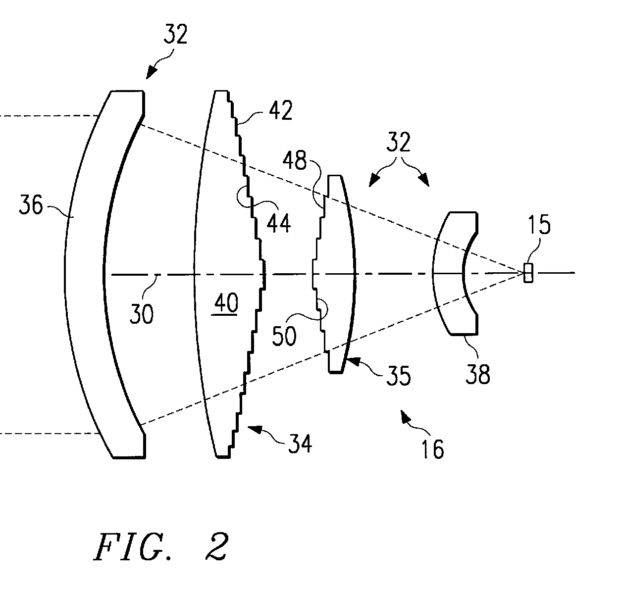
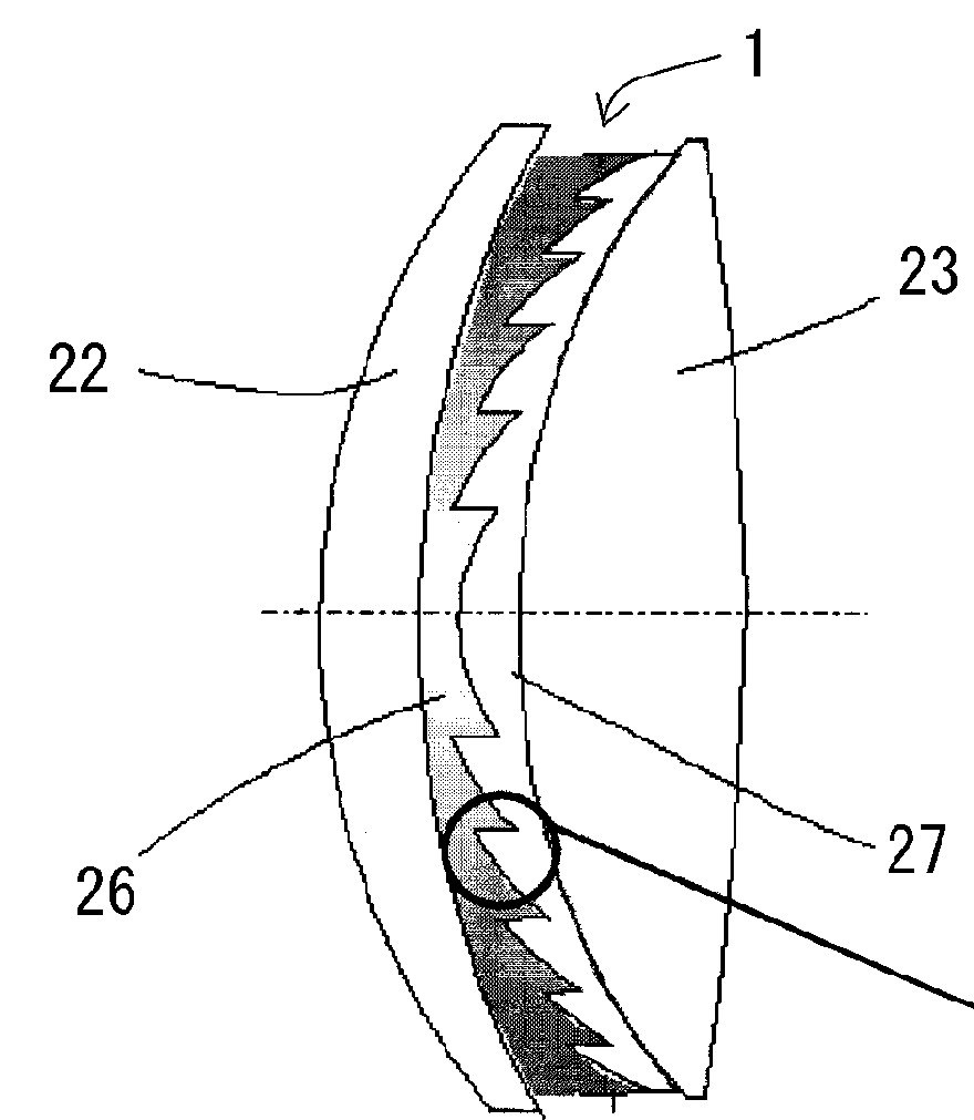
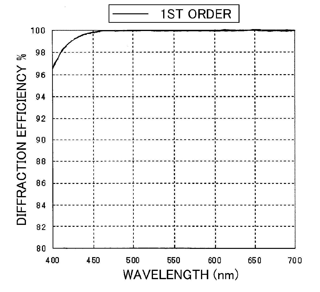
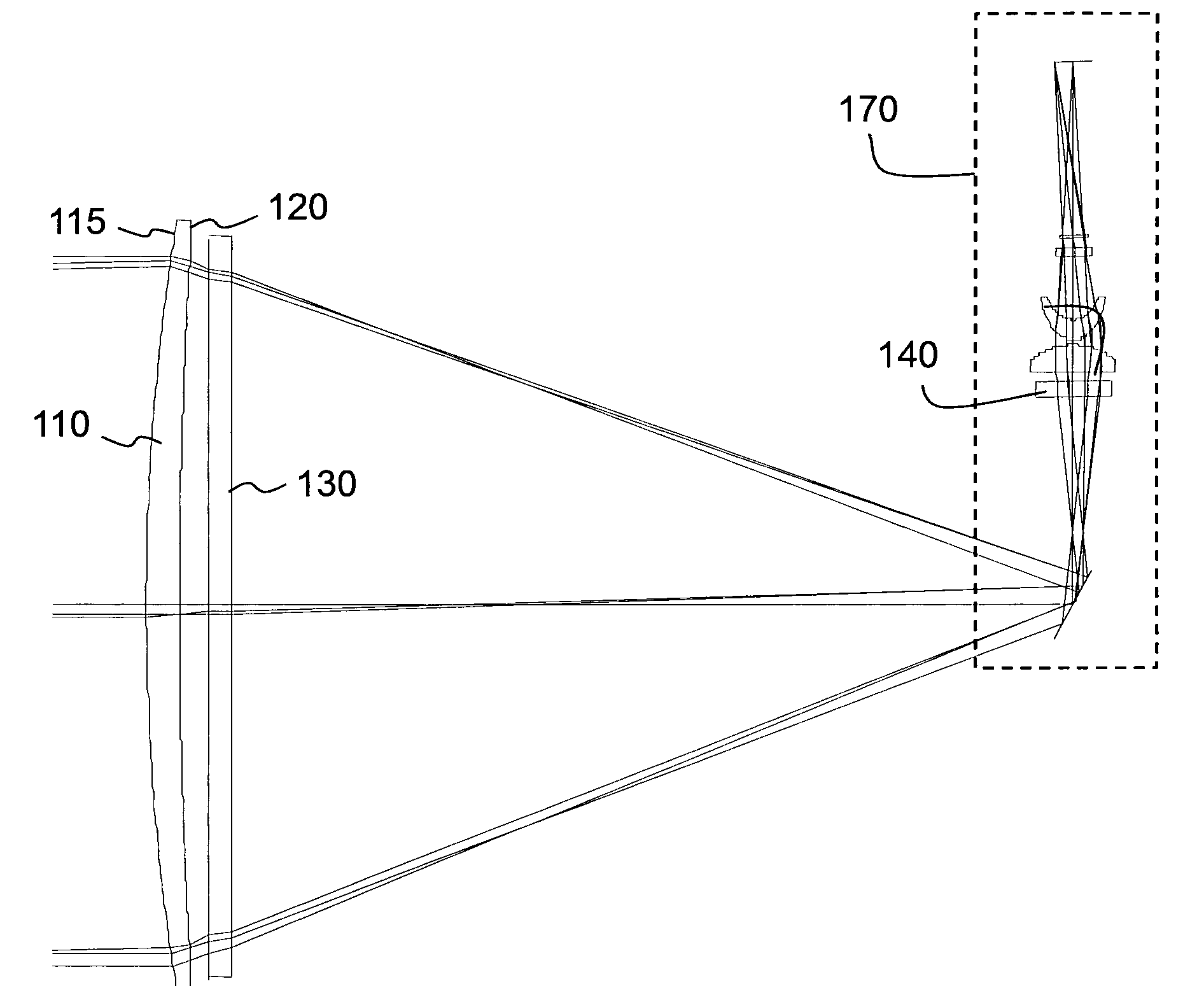
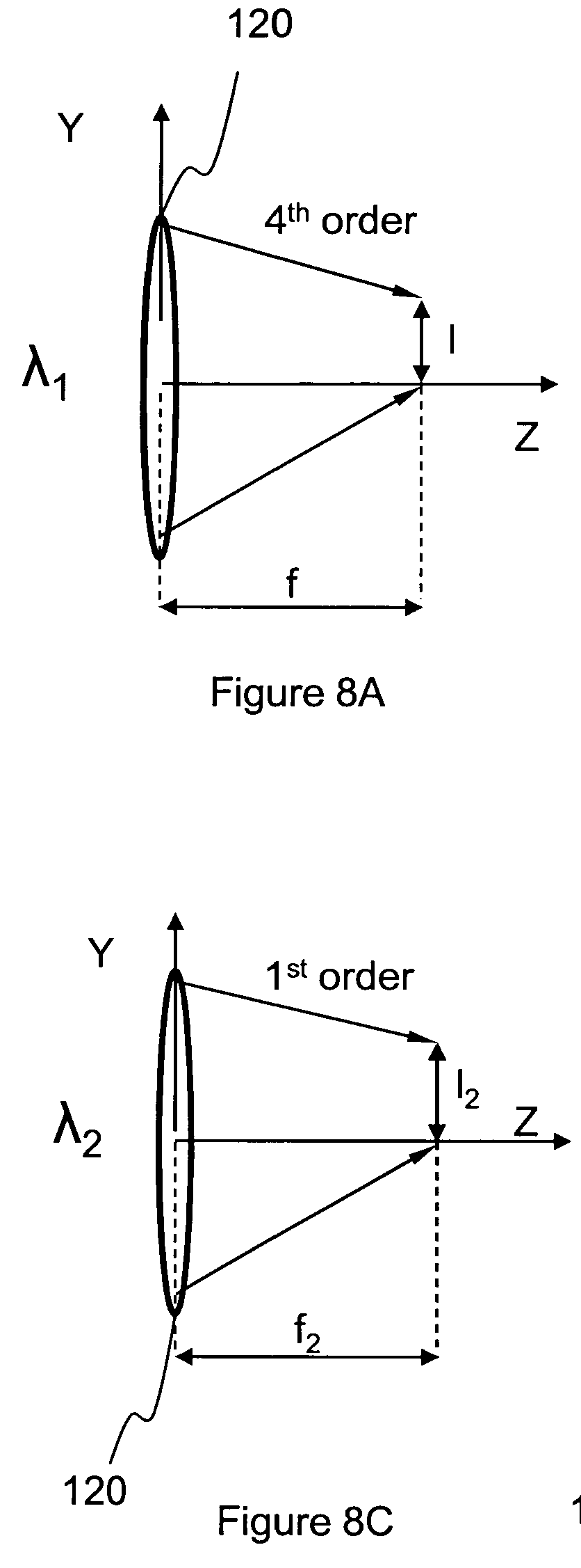
This place does not cover:
Stereoscopic systems |
Examples of places where the subject matter of this place is covered when specially adapted, used for a particular purpose, or incorporated in a larger system:
Of the protection type | |
Slide-changing apparatus |
Attention is drawn to the following places, which may be of interest for search:
Beam splitting or combining systems |
This place does not cover:
Systems using spatial filters |
Attention is drawn to the following places, which may be of interest for search:
Spectrometry |
Attention is drawn to the following places, which may be of interest for search:
Character recognition |
Attention is drawn to the following places, which may be of interest for search:
Speckle suppression in holography |
Attention is drawn to the following places, which may be of interest for search:
Means for converting the output of a sensing member using diffraction gratings |
Attention is drawn to the following places, which may be of interest for search:
Adjusting means being part of the system to be assembled |
In this place, the following terms or expressions are used with the meaning indicated:
Stereoscopic | with left and right images projected to the left and right eyes of an observer, who is required to view the image through an optical system placed adjacent to the eyes. |
In this place, the following terms or expressions are used with the meaning indicated:
Autostereoscopic | with left and right images projected to the left and right eyes of an observer, who is not required to view the images through an optical system placed adjacent to the eyes. |