CPC Definition - Subclass F03B
This place covers:
Engines driven by liquids and machines for liquids, other than of positive-displacement type.
This place does not cover:
Machines for liquids and gases | |
Positive-displacement engines for liquid | |
Ocean thermal energy conversion (OTEC) | |
Positive-displacement machines for liquids | |
Rotary fluid gearing of the hydrokinetic type |
Attention is drawn to the following places, which may be of interest for search:
This place covers:
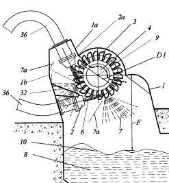
Engines of impulse type, i.e. turbines with jets of high-velocity liquid impinging on blades or like rotors, e.g. Pelton wheels; Parts or details peculiar thereto.
In these engines the energy - usually potential - of the liquid is entirely transformed into kinetic energy (or momentum) in the nozzle system, before the liquid reaches the runner or rotor.
Another way of defining these engines is to say that in an impulse turbine the runner or rotor is not enclosed by a pressurised space or casing, but placed within a space which is normally at atmospheric pressure.
DE202004019537U
This place covers:
Machines or engines of reaction type; Parts or details peculiar thereto.
A reaction type machine or engine in which the potential energy of the liquid is transformed into mechanical energy partly in the stator and partly in the rotor, in other words the fluid is forced to accelerate by a decrease in the available cross reaction, in both sections. Both the stator and rotor spaces are completely filled with the liquid whilst in operation, at a pressure higher than atmospheric.
A special case is when all the energy is transformed in the rotor, the so called Hero's turbine.
FR935827
This place covers:
Turbines in which all the potential energy of the liquid is transformed by acceleration in the rotor itself, causing the reaction which drives the turbine. The typical example is the Greek Hero's turbine - although that one was driven by steam. A rotating garden sprinkler uses this effect.
WO9612872
This place covers:
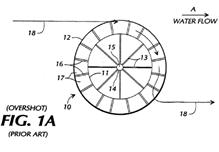
Water wheels which convert the potential energy of the liquid due to height differences, in this case up to a few meters.
The channels conveying the fluid to the water wheel are open to atmosphere.
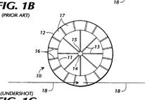
The traditional distinction between overshot and undershot water wheels refers to whether the point of introduction of the fluid onto the wheel is above or below the axis of rotation of the wheel. This distinction is not reflected (yet) in the classification.
Undershot water wheels use small gradients, but greater that the minimum incline which would still cause flow. They often have no buckets but blades.
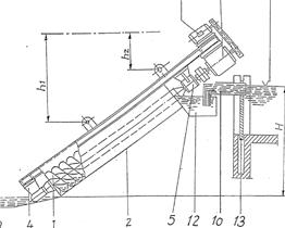
An Archimedes screw is also a water wheel in this sense when it extracts power from the potential difference on the fluid.
Examples:
Overshot
Undershot
Archimedes screw
When the device uses a flow with a minimal gradient, like a slow river, just enough to maintain the flow, documents should be classified in F03B 17/06
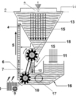
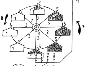
This place covers:
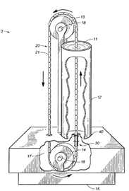
Machines where the collecting and transmitting the energy of a fluid is done with the help of a flexible continuous member closing on itself, which is maintained in place whilst moving with the help of rotating elements.
The flexible continuous member can be made of hinged elements ( as a bicycle chain) or consist of an elongated member also closing on itself, like a rope loop or a belt.
This flexible continuous member closing on itself ( "sans-fin" in French, also internationally known) is held in place whilst it travels by usually two, sometimes more than two, rotating guiding elements, like pulleys or toothed wheels.
Usually the elements directly interacting with the fluid flow (collecting its energy), in the form of buckets or paddles, are attached to the flexible continuous member at regular intervals along its length.
Any device using these elements in F03B is either a water wheel (see F03B 7/006 and subdivisions), or a machine using only the kinetic energy of a liquid flow (see F03B 17/06 and subdivisions).The group F03B 9/00 is therefore not used anymore for classifying new documents. Instead classify in the corresponding water wheel or liquid flow machine groups; that is, any hydraulic motor involving an endless chain arrangement should be classified in either water wheels F03B 7/006 or in machines using liquid flow F03B 17/06.
This place does not cover:
Turbines having means for functioning as pumps |
Attention is drawn to the following places, which may be of interest for search:
Wind motor combined with water energy converters | |
Wind motor combined with energy storage in form of liquid gravitational energy |
In patent documents, the following words/expressions are often used as synonyms:
- "pump storage", "hydroelectric schemes" and "stations"
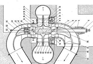
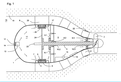
This place covers:
An installation where the turbine (usually propeller type), the gearbox (if any) and the electrical generator are all enclosed in a watertight enclosure (the "bulb") which is submerged and completely surrounded by the fluid from which the group extracts energy.
DE102008017537
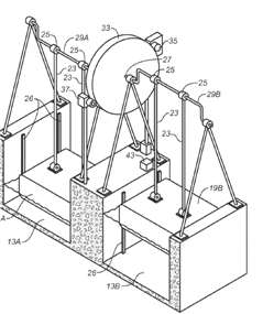
This place covers:
For a mechanical energy collection there must be a relative movement between a member directly acted upon by the waves (the Wave Operated Member or "wom" for short) and some other reaction structure or member relative to which the "wom" moves. This reaction structure is called REaction Member or "rem" (for short).
F03B 13/18 and subgroups: the REM is fixed with respect to the sea bed or shore, there are then 4 basic possibilities reflected in the subgroups:
F03B 13/188: Relative movement between WOM and REM happens because of flexibility of the WOM.
F03B 13/1805: Relative movement between WOM and REM is a rotation
F03B 13/1845: Relative movement between WOM and REM is a sliding movement
F03B 13/1885: Relative movement between WOM and REM is allowed by the WOM being tied to the REM, in a movement with three degrees of freedom
F03B 13/20: both members are movable relative to sea bed or shore, i.e. neither the WOM or the REM are motionless, the only constraint will be some form of anchoring to retain the whole device in the desired position.
Example :
GB297720
This place covers:
The waves indirectly cause a flow of liquid somewhere, which then drives a motor or turbine.
DE102008016839
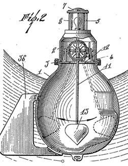
This place covers:
Normally it is some form of a (large and heavy) float which moves up and down with the tide, this movement being converted by various means in a usable form of energy.
US3567953
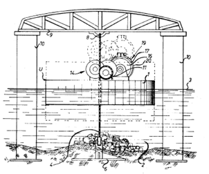
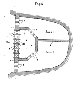
This place covers:
The tide is collected in a basin closed by dams with sluices, which are open when the tide is rising. At the highest point of the tide the sluices are closed. The trapped water is then allowed to escape through turbines back to sea level until the tide turns again.
US1785896
This place covers:
Turbines driven by fluid with (height) potential energy, which drives a generator to produce electricity, and a pump which returns the fluid to the original height.
WO2004094816
This place covers:
Turbines in which the conversion of energy is made thanks to the hydrostatic vertical thrust of objects lighter than water experienced when submerged. Often uses additional compressed air in which case the device is a motor.
DE10200903
This place covers:
Floats which usually follow alternative water levels. Also containers (floats) which are alternatively filled and emptied within a water basin. All these devices are motors.
WO201106632
This place covers:
Perpetua mobilia of alleged kind, i.e. devices where the hydrostatic thrust effect is used to supposedly drive a device continuously, without input of energy, or of additional energy after the start, even when the concept perpetual is not explicitly mentioned.
US2010223922
This place covers:
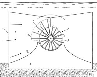
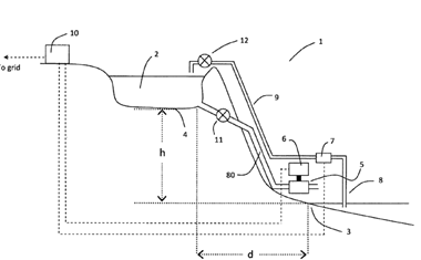
Machines or engines using liquid flow with predominantly kinetic energy conversion, e.g. of swinging-flap type, "run-of-river", "ultra-low head".
The term "liquid flow" is meant here to refer to fluid flows with minimal gradient, little more than that necessary for maintaining the flow, like for instance in calm rivers. The energy being converted is thus the kinetic energy of the flow, rather than its potential (height) energy, as in older, conventional hydro(electric) schemes involving large height differences, or even medium to small height ("head") differences, used in water wheel type devices.
When the water flow is caused by the tides F03B 13/264,
In this place, the following terms or expressions are used with the meaning indicated:
Rotation axis | Rotational axis of the device converting the kinetic energy. |
In patent documents, the following words/expressions are often used as synonyms:
- "run-of-river" and "ultra low head"
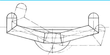
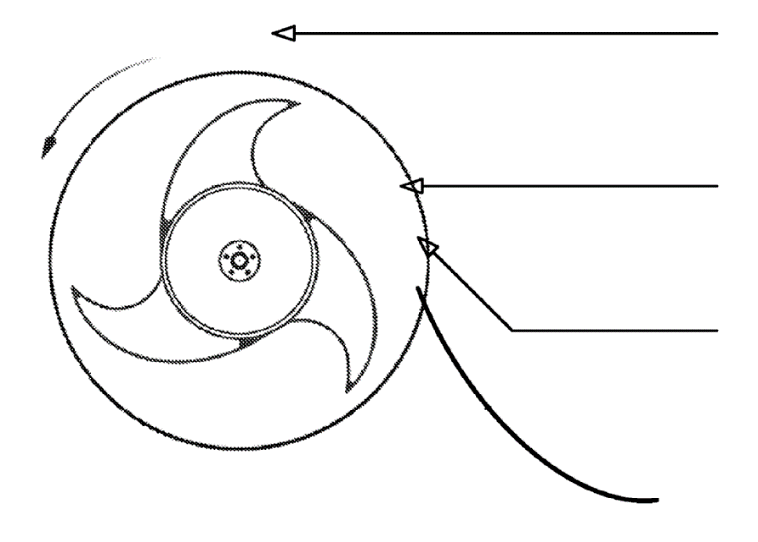
This place covers:
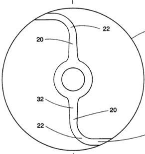
Machines or engines in which the flow engaging parts, i.e. the elements in contact with the flow, transferring its kinetic energy to the rest of the converting device, are permanently and rigidly fixed to the rest of the structure of the converter.
Illustrative example of subject matter classified in this group:
This place covers:
Machines or engines in which the concept "cyclic movement" refers to the relative movement of the flow engaging parts with respect to the rest of the converter structure, where the parts adopt different positions depending on the rotational position of the whole converter structure as it rotates about its axis, returning to the original position after each revolution. When coupled to the movement of rotation then F03B 17/067.
WO03029646