CPC Definition - Subclass E05B
This place covers:
Locks for swingable, slidable, or otherwise movable wings, e.g. doors or windows, for restricting access, which are usually, but not necessarily always, unlocked by means of a key or equivalent means, e.g. combination means, electrical means, etc. It also covers handles or knobs for wings, including handles for wings which do not operate the locking mechanism. It additionally covers latching or locking means for other movable structures such as drawers, lids of chests, vehicle doors, vehicle lids for luggage or engine compartments, to which the locking means covered by this subclass may be applied. It further covers devices for locking clothing, locks specially adapted for bicycles, locks for locking portable objects against unauthorised removal and handcuffs.
- Bolts or fastening devices for wings, specially for doors or windows: E05C;
- Hinges or other suspension devices for door, windows or wings: E05D;
- Devices for moving wings into open or closed positions: E05F;
- Safes or strong-rooms: E05G;
- Door, windows, shutters, roller blinds, gate: E06B
- Individual entry or exist registers: G07C 9/00
This place does not cover:
Buckles; Similar fasteners for interconnecting straps or the like | |
Devices for fastening or securing constructional elements or machine parts together | |
Electronic locks |
Examples of places where the subject matter of this place is covered when specially adapted, used for a particular purpose, or incorporated in a larger system:
Door latches for dish washers | |
Locking devices for vehicle seats, e.g. for back rests or for locking a seat relative to the floor | |
Locking devices for container closures | |
Locking or fastening means for lids or covers of refuse receptacles | |
Locks for washing machines | |
Locking of doors, covers, guards acting in conjunction with the control or operation of a machine | |
Latches for doors specially adapted for stoves |
In this place, the following terms or expressions are used with the meaning indicated:
Bolt | means a sliding, pivoted, or otherwise movable member such as is normally carried by a door to hold it shut by engagement with a keeper on the frame. It may be operated by hand directly or through mechanism or by a key; it may be a latch (see below); |
Frame | means any member to which a wing may be held by a fastening device. It does not include a framework forming part of the wing, but it may be another wing. |
Hasp | means a member hinged to the frame or wing so that it can be moved towards the face of the wing or frame and secured thereto, e.g. by a turn-button, by a padlock and staple. |
Latch | means a bolt arranged to be moved to the releasing position against the force of a spring, or some other returning force, when a wing meets the frame on closing, so that it does not have to be operated by hand to secure the wing, but only to open it. |
Lock | means primarily a device for releasing or securing any member, which requires a key or a permutation mechanism for release. In groups E05B 1/00- E05B 9/00, E05B 13/00- E05B 17/00, E05B 39/00- E05B 47/00, E05B 51/00, E05B 53/00, E05B 63/00 and E05B 65/00 however, the term "lock" may include other fastening devices. |
Wing | is a general term for swingable, slidable, or otherwise movable doors or windows. This term also includes other movable structures such as drawers, lids of chests, car boots, or car bonnets, to which the operating, mounting, latching, or locking means covered by this class may be applied. |
This place covers:
Knobs, handles or push-buttons for wings. The handles can be movable or non-movable
This place does not cover:
Examples of places where the subject matter of this place is covered when specially adapted, used for a particular purpose, or incorporated in a larger system:
Handles for vehicles | |
Knobs or handles for furniture | |
Straps provided with handles for bundling articles | |
Controlling members for hand actuation, e.g. handles |
Attention is drawn to the following places, which may be of interest for search:
Handles for suitcases or travelling bags | |
Handles for carrying purposes | |
Methods or apparatus for disinfecting materials | |
Handles for hand implements, e.g. for tools | |
Handgrips or straps for passengers in vehicles | |
Handles for containers | |
Handles for sacks or bags | |
Details of refrigerator doors |
This place covers:
Fastening the knob or handle to lock or latch parts, in particular to the lock spindle, as well as fastening the spindle to the lock follower.
This place does not cover:
Mounting handles to a vehicle wing |
Attention is drawn to the following places, which may be of interest for search:
Mounting of handles which do not operate the bolt | |
Fastening locks or fasteners or parts thereof to the wing |
This place covers:
Handles which are flush when mounted to a wing and pop-out handles.
This place does not cover:
Handles for vehicles |
This place covers:
Handles pivoted about an axis parallel to the wing
This place does not cover:
Handles for vehicles |
This place covers:
Lock or latch mechanism casings of latch bolt locks, of dead bolt locks and of cylinder locks;
Face plates;
Fastening of locks or parts thereof to the wing;
Coupling devices for the two halves of a double cylinder lock.
This group has the following structure:
Faceplates or front plates | |
Casing of latch bolt or dead bolt locks | |
Casing of cylinder locks | |
Fastening locks or fasteners or parts thereof, e.g. the casings of latch bolt or dead bolt locks to the wing | |
Fastening of lock cylinders to the wing | |
Fastening plugs or cores to an outer stator | |
Coupling devices for the two halves of double cylinder locks |
This place does not cover:
Padlock casings | |
Mounting of lock casings to the vehicles | |
Mounting of lock casings to vehicles |
Attention is drawn to the following places, which may be of interest for search:
Handles which do not operate the bolt | |
Fastening locks for glass wings |
This place does not cover:
Using a pair of interlocked keys |
Attention is drawn to the following places, which may be of interest for search:
Preventing turning of the key | |
Keyholes guards |
This place covers:
Covers preventing access to the handle or key;
Devices for locking the handle;
Devices for disconnecting the handle;
This place does not cover:
Electrically locking the handle | |
Electrically disconnecting the handle | |
Disconnecting the handle in a lock in which a sliding latch is used as a locking bolt |
Attention is drawn to the following places, which may be of interest for search:
Closures or guards for keyholes |
This place covers:
Other details and parts of locks according to the following structure:
Devices for aligning wing and frame; Anti-rattling devices | |
Followers; bearings therefor | |
Energy storage by movement of the wing | |
Adaptors cooperating with and acting on keys inserted in an existing lock | |
Spindles for handles, i.e. square spindles | |
Lost motion connections | |
Ratchet mechanisms | |
Means providing a stable position for lock parts | |
Toggle levers | |
Gravity actuated lock parts | |
Escutcheon plates | |
Striking plates, keepers | |
Spring arrangement in locks | |
Lock wards | |
Key guides | |
Bolts of locks | |
Tumblers | |
Use of special materials for parts of the locks |
- Bolts or fastening devices for wings, specially for doors or windows: E05C.
Attention is drawn to the following places, which may be of interest for search:
Spring biasing means for moving the handle | |
Wound springs | |
Modifying spring characteristic or tension | |
Attachments or mountings; Mounting of springs | |
Units of springs; Two or more springs working together | |
Folded springs | |
Torsion springs of bar type | |
Leaf springs; Non-wound wire springs | |
Ring springs | |
Cup- or dished-disc springs | |
Made of one piece with a lock part | |
Made of rubber, plastics or the like | |
Heavy springs which cannot be operated by hand | |
A single spring working on more than one part | |
Overcenter springs | |
Springs actuated by cams or the like | |
For the whole lock | |
For bolts | |
For escutcheons | |
For lock housing | |
For strikers | |
For handle bearings | |
Using special materials for keys | |
Electric strikers | |
Gravity mechanisms for brief or suitcases | |
Staples for padlocks | |
Gravity arrangements related to vehicle accidents | |
Anti-rattling means in vehicles | |
Strikers for vehicles | |
Bolts or detents for vehicle locks | |
Fastening devices for wings other than locks or associated with locks | |
Strikers for espagnolette locks | |
Securing part is formed by a spring, e.g. snaps | |
Toggle fasteners | |
Finger plates |
Examples of places in relation to which this place is residual:
Use of special materials for handles |
Attention is drawn to the following places, which may be of interest for search:
For reducing friction | |
For keys |
This place covers:
Accessories in connection with locks according to the following structure:
Lock assembling or manufacturing | |
Defrosting, heating devices | |
Weather or dirt protection | |
Devices for forcing the wing against its seat or to initiate opening of the wing | |
Damping means | |
Silencing devices, noise reduction | |
Preventing accidental lock-out | |
Fraction or shear lines | |
Insulating, e.g. for limiting heat transfer | |
Devices for coupling the turning cylinder with the bolt operating member | |
Templates or apparatus for installing locks | |
Lubricating devices | |
Illuminating devices | |
Devices for removing key stuck in the lock | |
Closures or guards for keyholes | |
Means independent of the locking mechanism for preventing unauthorised opening, e.g. by attack | |
Means for operating or controlling locking mechanisms, e.g. switches, indicators |
- Bolts or fastening devices for wings, specially for doors or windows: E05C.
This place does not cover:
Preventing dirt into the striker | |
Illuminating devices attached to key rings | |
With means carried by the lock for interlocking with the keeper | |
Additional locking for safes responsive to attack | |
Weather protection for vehicles | |
Noise prevention, anti-rattling means in vehicles | |
Cushion elements in vehicles | |
Vehicle locks elements covered by a silencing coating | |
Means for damping the movement of vehicle lock parts | |
Burglar prevention in vehicles, e.g. by opening by unauthorised tool | |
For assisting closing vehicle doors | |
Making locksmith's goods of sheet metal, e.g. handles | |
Drill jibs for work pieces | |
Assembling in general | |
Slotted or mortise work | |
Using toothed wheels between lock cylinder and operating bars in espagnolette locks | |
Templates for hinges | |
Anti-tampering devices for hinges | |
Stops or buffers preventing slamming of the wings | |
Means for taking the weight of the wing |
Attention is drawn to the following places, which may be of interest for search:
Devices for holding pieces while being painted | |
Means for preventing rattling of the wing | |
Switches associated with locking means of the closing member |
This place covers:
Keys for locks and accessories therefor and it has the following structure:
Key safes, i.e. lockable container for safe storage of one or a few keys | |
Key decoders | |
Key profiles | |
Construction of the key head, attaching the head to the shank | |
Double or multiple keys | |
Keys adjustable before use | |
Skeleton keys; devices for picking up locks | |
Keys indicating whether the last operation was locking or unlocking | |
Key distinguishing marks | |
Use of special materials for keys |
- Individual entry or exist registers G07C 9/00.
This place does not cover:
Key modifications or attachments preventing removal from the lock | |
Key rings | |
Key cases; e.g. purses for keys or small cases for extendable/retractable storage of several keys or shanks (however for single keys/shanks E05B 19/0082, E05B 19/043, E05B 19/046) | |
Key holders; boards or cabinets for key storage | |
Rescue tools with forcing action | |
Making keys | |
Milling grooves in keys |
Attention is drawn to the following places, which may be of interest for search:
Illuminating devices on keys | |
Locks for use with special keys | |
Keys with magnets | |
Mechanical keys for electric permutation locks | |
Key manufacturing | |
Non-mechanical keys for electronic locks |
This place covers:
Locks with plate tumblers wherein, when the correct key is inserted into the lock, the tumblers are not immediately moved to their unlocked positions. Only when the key is thereafter turned, the tumblers are moved to their unlocked positions. The movement of the tumblers does not follow the movement of the bolt, which means that the tumblers usually are mounted to the lock housing. This group has the following structure:
Chubb locks | |
Cylinder locks, e.g. Protector locks | |
Cylinder locks of the sliding-plate tumble type | |
Cylinder locks of the rotary-disc tumbler type |
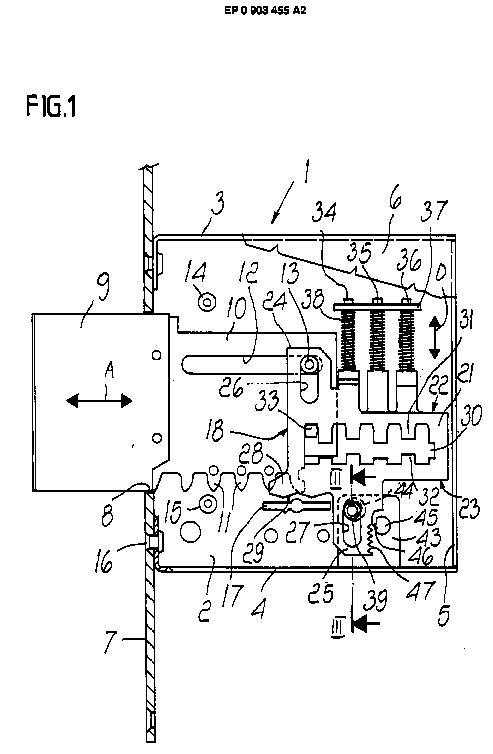 EP0903455
E05B 21/00 should contain locks with tumblers moved by rotation of the key in which, when the key is turned, the movement of the tumblers is independent of the movement of the bolt, e.g. the tumblers are guided in the lock casing for movement in a direction perpendicularly to the movement direction of the bolt.
This place covers:
Cylinder locks wherein the tumblers are not set by pushing the key in.
 DE560425
This place covers:
Cylinder locks with rotary-disc tumblers wherein the tumblers are not set by pushing the key in.
 EP0978608
Cylinder locks with rotary tumblers, such that when the key is inserted into the lock the tumblers are set should be classified in E05B 29/0013.
This place covers:
Locks, other than cylinder locks, wherein when the key is turned to move the bolt the tumblers follow the movement of the bolt, e.g. the tumblers are pivotally mounted on the bolt.
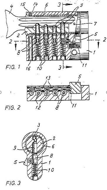
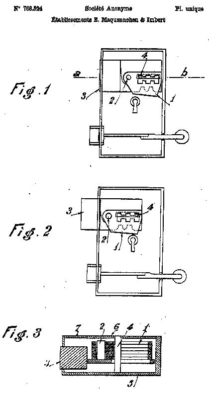 FR768524
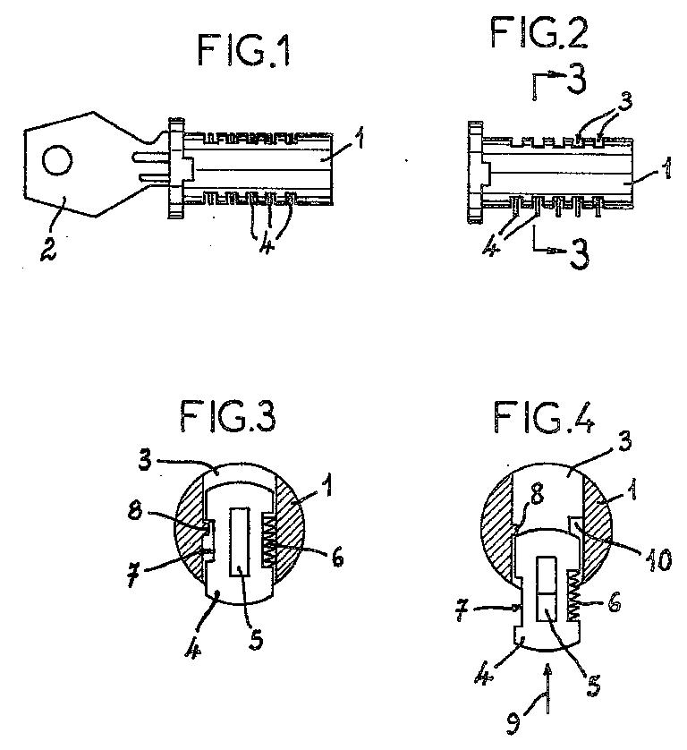
This place covers:
Cylinder locks with tumbler pins or balls which are set by pushing the key in and parts thereof, i.e. rotors, stators and tumblers.
Attention is drawn to the following places, which may be of interest for search:
Casing of cylinder locks | |
Fastening of lock cylinders to the wing | |
Fastening plugs or cores to an outer stator | |
Coupling devices for the two halves of double cylinder locks | |
Cylinder locks with magnetic tumblers | |
Cylinder locks with electromagnetic control | |
Lock cylinder arrangements vehicles |
This place covers:
Cylinder locks with plate tumblers which are set by pushing the key in. The plate tumblers can slide, rotate or float, e.g. slide and rotate.
 FR768524
This place does not cover:
Lock cylinder arrangements vehicles |
Attention is drawn to the following places, which may be of interest for search:
Casing of cylinder locks | |
Fastening of lock cylinders to the wing | |
Fastening plugs or cores to an outer stator | |
Coupling devices for the two halves of double cylinder locks | |
Cylinder locks with magnetic tumblers | |
Cylinder locks with electromagnetic control |
This place covers:
Cylinder locks with rotary tumblers, wherein, when the key is inserted into the lock the tumblers are set to the right combination.
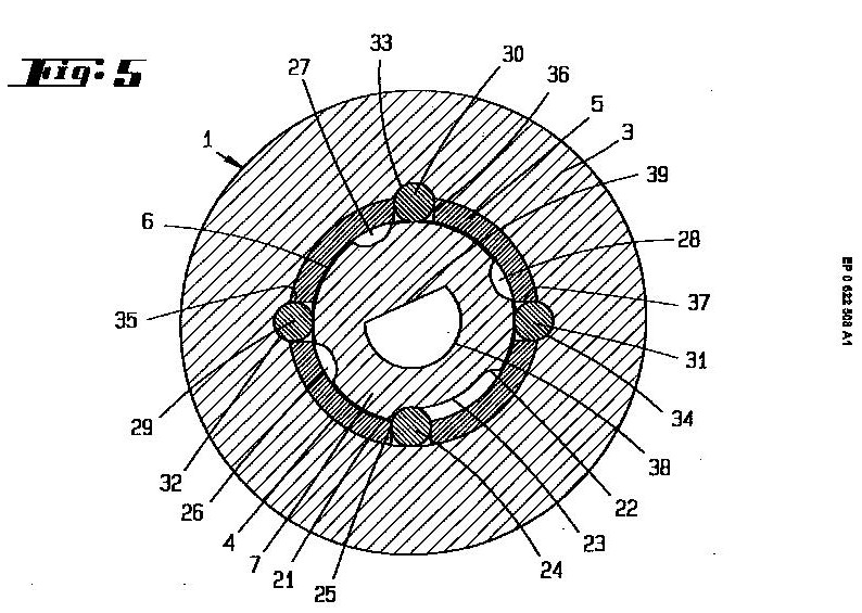 EP0622508
Cylinder locks with rotary tumblers, wherein, when the key is inserted into the lock the tumblers are not set, e.g. do not move, and when during rotation of the key the tumblers are set to the right combination should be classified in E05B 21/066.
This place covers:
Cylinder locks with both tumbler pins or balls and plate tumblers which are set by pushing the key in.
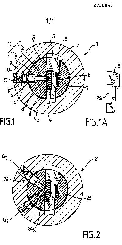 FR2758847
This place covers:
Cylinder locks with tumblers which are set by pushing the key in and wherein the rotor is moved by means other than the key.
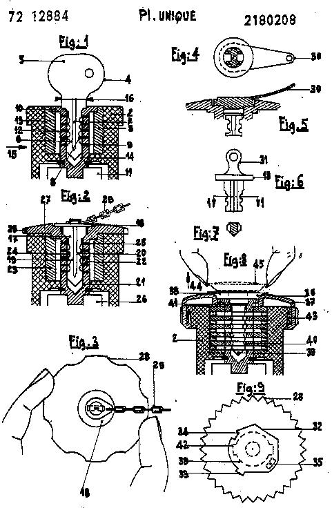 FR2180208
Attention is drawn to the following places, which may be of interest for search:
Cylinder locks operated by handles, e.g. by knobs | |
Cylinder locks with electromagnetic control operated by handles, e.g. knobs |
This place covers:
This group has the following structure:
With key identifying function | |
For flexible keys | |
For keys with movable bits | |
For rack- or pinion-like keys | |
The key being a perforated card or the like | |
For simple tool-like keys | |
Which can be shifted laterally or rotated about an axis perpendicular to the key axis | |
For screw keys | |
Operable by a plurality of key | |
With master and pass keys | |
Requiring the use of two keys | |
With keys that different parts operate separate mechanisms |
This place does not cover:
Keys adjustable before use | |
Mechanical locks operated by cards having magnets | |
Keys with magnets | |
Mechanical keys for electric permutation locks | |
Non-mechanical keys for electronic locks |
Attention is drawn to the following places, which may be of interest for search:
Key; accessories therefor | |
Cylinder locks with tumbler pins or balls | |
Cylinder locks with plate tumblers |
This place covers:
Mechanical combination locks, padlocks with combination locks and puzzle locks.
- Individual entry or exist registers G07C 9/00.
This place does not cover:
Handles with combination locks | |
Keyhole guards with combination locks | |
Electric permutation locks |
Examples of places where the subject matter of this place is covered when specially adapted, used for a particular purpose, or incorporated in a larger system:
Permutation locks for container closures |
Attention is drawn to the following places, which may be of interest for search:
Alarms for combination locks | |
Electronic permutation locks | |
Combination switches |
This place covers:
Locks with means giving indication of authorised or unauthorised unlocking and also locks with non-electronic counting or registering devices.
This place does not cover:
Closures for postal containers with special means for indicating unauthorised opening | |
Locking devices for container closures with means for indicating unauthorised opening | |
Time recording locks (electronically) | |
Security seals |
Attention is drawn to the following places, which may be of interest for search:
Locks with key identification function | |
Alarm locks | |
Vehicle locks with means for sealing |
Attention is drawn to the following places, which may be of interest for search:
Seals per se |
Attention is drawn to the following places, which may be of interest for search:
Illuminating devices | |
Switches, indicators |
This place covers:
Time locks, e.g. with delaying means and timers devices controlling electrically operated locks.
- Mechanically driven clocks or watches G04B 23/00
- Registering indicating or recording the time G07C 1/00;
- Time medicine dispensers A61G 7/00;
Attention is drawn to the following places, which may be of interest for search:
Electrically operated locks | |
Electric permutation locks | |
Medicine programmed dispensers | |
Clocks or clock mechanisms with attached or built-in means operating any device at preselected times or after preselected time-intervals | |
Time recording locks |
This place covers:
Locks provided with mechanical or electrically operated alarms, including chain, cables or padlock with alarms.
- Alarms systems G08B
- Vehicle fittings preventing or indicating unauthorised used or theft B60R 25/00;
- Appliances indicating unauthorised use or theft of cycles B62H 5/00;
- Safe or strong rooms E05G 1/00;
Attention is drawn to the following places, which may be of interest for search:
Electric operated locks | |
Electric permutation locks | |
Vehicle theft alarms | |
Bicycle theft alarms | |
Safe or strong rooms with alarms | |
Detonating alarm devices in general | |
Alarm devices(other than the lock itself) actuated by tampering with fastenings in general |
This place covers:
Locks or other fastening devices comprising electric or magnetic means for operation or control the lock functions. It has the following main structure:
This place does not cover:
Electric permutation locks |
Examples of places where the subject matter of this place is covered when specially adapted, used for a particular purpose, or incorporated in a larger system:
Power-actuated vehicle locks |
Attention is drawn to the following places, which may be of interest for search:
Motor-operated | |
Electrically-operated | |
Devices for holding wings in open position or limiting movement of wings by magnetic or electromagnetic attraction | |
Device holding the wing by magnetic or electromagnetic attraction | |
Key switches |
This place covers:
Electric permutation locks and mechanical keys therefor. It has the following main structure:
Keys with mechanical characteristics | |
Keys actuating mechanical switches | |
Keys actuating opto-electronic devices |
- Methods of sensing or reading record carriers G06K 7/00;
- Recognition of data, record carriers G07F 7/00;
- Mechanisms including electronic locks actuated by non mechanical keys such as passive and active electrical keys: G07C 9/00
- Mechanism actuated by coded cards: G07F 7/00
- Electronic switching or gating: H03K 17/00
This place does not cover:
Electric operated or controlled locks | |
Electronic locks actuated by non mechanical keys | |
Non-mechanical keys for electronic locks |
Examples of places where the subject matter of this place is covered when specially adapted, used for a particular purpose, or incorporated in a larger system:
Key operated switches |
This place covers:
Operating or controlling locks or other fastening devices by other non-purely mechanical means, such as e.g. by bimetallic or memory-shaped elements, or by pneumatic or hydraulic means.
This place does not cover:
Opening a panic door under force or pressure on the surface of the door | |
Locking several vehicle wings simultaneously by pneumatic or hydraulic means | |
Pneumatic or hydraulic driven locks for vehicles and actuators or circuits therefor | |
Hydraulic power locks for wing closers | |
Power operated mechanism for wings with pressure medium |
Attention is drawn to the following places, which may be of interest for search:
Thermo-electric actuators |
This place covers:
Locks operated by mechanical transmission including foot-operated locks and locks operated by flexible means, e.g. cables or Bowden cables.
This place does not cover:
Flexible connections between lock parts in vehicles | |
Mechanical operating mechanisms for wings |
Examples of places where the subject matter of this place is covered when specially adapted, used for a particular purpose, or incorporated in a larger system:
Means for transmitting linear movement in a flexible sheathing, e.g. Bowden mechanisms |
Attention is drawn to the following places, which may be of interest for search:
For simultaneously actuated bolts | |
For car boot lids or bonnets | |
For fuel inlet covers |
This place covers:
Locks in which a sliding latch is used also as a locking bolt, e.g. cylindrical or tubular locks. It includes also locks in which the handle can be disconnected or locks in which the bolt is secured by the action of a trigger member cooperating with the frame.
This place does not cover:
Electrically disconnecting the handle | |
A latch bolt being initially retained in an intermediate position and subsequently projected to its full extend when the wing is closed |
Attention is drawn to the following places, which may be of interest for search:
Devices for disconnecting the handle | |
Cylindrical or tubular latches |
This place covers:
Locks in which a pivoted latch is also can be dead locked.
AU556425
This place covers:
Locks with latches in addition to lock-bolts or dead bolts.
EP0792980
- Bolts or fastening devices for wings, specially for doors or windows: E05C.
Attention is drawn to the following places, which may be of interest for search:
Bolts with multiple head | |
Locks in which a sliding latch is used also as a locking bolt | |
Other locks with provision for latching | |
Locks with a rotary bolt without provision of latching | |
Locks with a pivoting bolt without provision of latching | |
Mortise locks | |
Locks with several bolts | |
Automatic locks | |
Espagnolette locks |
This place covers:
Locks which provision of latching not covered by the groups E05B 55/00, E05B 57/00 or E05B 59/00.
This place covers:
Locks or fastenings with special structural characteristics
Bolts or fastening devices for wings, specially for doors or windows: E05C
Examples of places where the subject matter of this place is covered when specially adapted, used for a particular purpose, or incorporated in a larger system:
Using bolts interlocking with notches for attaching vehicle seats to the vehicle chassis | |
Safety devices for wings opening about a vertical as well as a horizontal axis |
This place does not cover:
Bolts with multiple head | |
With provision for latching |
Examples of places where the subject matter of this place is covered when specially adapted, used for a particular purpose, or incorporated in a larger system:
Locks for sliding wings having simultaneously pivoting double hook-like locking members | |
Bolts for vehicle locks rotating about an axis and being bifurcated | |
Double bolts being bifurcated and spring actuated for wings, doors or windows |
Attention is drawn to the following places, which may be of interest for search:
Locks for keys with several bits | |
Arrangements of simultaneously actuated bolts or other securing devices at well-separated positions on the same wing |
This place does not cover:
Operating or controlling locks using electric or magnetic means in the striker or on the frame | |
Adaptation of locks - locking the bolt by an electromagnet in the striker | |
Locks with means carried by the bolt for interlocking with the keeper and having additional bolt in the striker | |
Hasp locks |
Attention is drawn to the following places, which may be of interest for search:
Hasp fastenings |
This place covers:
Locks or fastenings for special use.
Examples of places where the subject matter of this place is covered when specially adapted, used for a particular purpose, or incorporated in a larger system:
Weight arrangement in locks | |
Arrangements of fasteners for travelling bags | |
Drawers for tables, cabinets or like furniture | |
Coffin closures | |
Arrangement of water tight doors in bulkheads | |
Applications of locks for container closures | |
Locking devices for elevator doors or gates | |
Locking devices for manhole covers | |
Connections for building structures withrotatable locking means | |
Vertically sliding sectional doors | |
Gas-proof doors or similar closures | |
Wire gates | |
Covers or closures for pressure vessels | |
Details of doors or covers of refrigerators | |
Latching mechanisms for covers of portable computers | |
Enclosures for switching arrangements |
Attention is drawn to the following places, which may be of interest for search:
Insulating, e.g. for limiting heat transfer | |
Locks with fracturable glass or the like | |
Locks with visible indication as to whether the lock is locked or unlocked | |
Locks for vehicles | |
Locks for sliding doors of vehicles | |
Buckles, similar fasteners for interconnecting straps | |
Slide fasteners | |
Door latches for dish washers | |
Locking devices for vehicle seats | |
Hatch fastening in ships | |
Locking devices for container closures | |
Locking or fastening means for lids or covers of refuse receptacles | |
Safety arrangements for laundry washing machines | |
Securing means for doors of laundry washing machines | |
Locks for two wings | |
Holding sliding wings open | |
Toggle fasteners | |
Devices for holding the wing by magnetic attraction | |
Magnetic gaskets | |
Locking of doors, covers, guards acting in conjunction with the control or operation of a machine | |
Latches for doors specially adapted for stoves | |
Coin freed locks | |
Switches operated by a key |
This place covers:
Locks or fastenings for sliding wings.
Attention is drawn to the following places, which may be of interest for search:
For vehicles | |
Holding sliding wings open |
Attention is drawn to the following places, which may be of interest for search:
Connections between frontal surfaces of slab-shaped building elements with rotatable locking means co-operating with a recess | |
Toggle fasteners in general |
This place covers:
Locks for furniture.
This place does not cover:
Locks for drawers |
This place covers:
Locks for drawers.
Attention is drawn to the following places, which may be of interest for search:
For electronic unit cases |
This place covers:
Locks for two or more drawers using rotary locking bars.
This place does not cover:
Drawer interlock or anti-tilt mechanisms with rotary locking bars | |
Locking bars secured in front of the drawers |
Examples of places in relation to which this place is residual:
Permutation locks | |
Hasp locks | |
Locking slide fasteners | |
Toggles |
Attention is drawn to the following places, which may be of interest for search:
Closures for bags or trunks |
This place covers:
Padlocks; Details thereof
This place does not cover:
Permutation locks |
Examples of places where the subject matter of this place is covered when specially adapted, used for a particular purpose, or incorporated in a larger system:
Anti-theft devices for vehicles operating on steering mechanism |
Attention is drawn to the following places, which may be of interest for search:
Chain cables or padlocks with alarms | |
Hasp locks | |
Lockable hangers or hanger racks | |
Hasp fastenings |
This place covers:
Devices for locking clothing, shoes, lockable hangers or hanger racks and lockable clothing hooks.
Shoe hangers, clothing, dress or hat holders: A47G 25/00
This place does not cover:
Chain cables or padlocks with alarms | |
Anti-theft tags or monitors |
Examples of places where the subject matter of this place is covered when specially adapted, used for a particular purpose, or incorporated in a larger system:
Shoe hangers | |
Dress holders | |
Cloth hooks | |
Hat holders | |
Clothing hangers |
Attention is drawn to the following places, which may be of interest for search:
Anti-theft monitors | |
Dress or hat holders in general |
This place does not cover:
For means for safe-keeping of property, left temporarily, e.g. by fastening the property |
This place covers:
Locks specially adapted for bicycles, other than padlocks
Locks integral with cycles, cycles stands: B62H
This place does not cover:
Attention is drawn to the following places, which may be of interest for search:
Supporting devices for attaching articles to cycles |
This place covers:
Devices for locking portable objects against unauthorised removal; Miscellaneous locking devices
This place does not cover:
Locks specially adapted for bicycles | |
Anti-theft arrangements for helmets | |
Devices for storing or displaying riffles or guns | |
Show cases with theft protection | |
Anti-theft means for display panels | |
Show stands with provision for preventing unauthorised removal | |
Anti-theft devices for skis or ski equipment | |
Covers cups or guards for traction coupling, hitches | |
Supporting devices for attaching articles to cycles |
Examples of places where the subject matter of this place is covered when specially adapted, used for a particular purpose, or incorporated in a larger system:
Walking sticks with locks | |
Umbrella stands or holders | |
Cases for storing record carrier discs |
Attention is drawn to the following places, which may be of interest for search:
Chain or cable locks | |
Lockable hangers or hanger racks | |
Hasp fastenings |
This place does not cover:
Locks integral with walking sticks |
Attention is drawn to the following places, which may be of interest for search:
Stick or umbrella holders in general |
This place covers:
Handcuffs; Finger cuffs; Leg irons; Handcuff holsters; Means for locking prisoners in automobiles
Examples of places where the subject matter of this place is covered when specially adapted, used for a particular purpose, or incorporated in a larger system:
Restraining devices for body parts |
This place does not cover:
Locks specially adapted for bicycles | |
Locking arrangements for nonfixed vehicle roofs |
In this place, the following terms or expressions are used with the meaning indicated:
latching/unlatching | holding/release of a bolt element that a wing or door can be opened. A typical vehicle lock is unlatched when a detent, pawl or ratchet releases the fork shaped bolt |
locking/unlocking | preventing/allowing an unlatching action. In the locked state an unlatching action, normally done by actuating a handle or grip, is prevented. A locked door or wing is at least prevented from being unlatched from outside of the vehicle |
This place covers:
Locks designed to perform or prevent certain functions in case of accidents
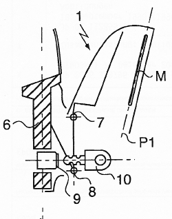
This place covers:
Locks, where an unwanted unlatching is prevented in case of an accident. One particular example is that a door handle could be accidentally actuated in case of a collision against the side door of a vehicle.
One way of preventing such an unwanted actuation is the provision of an extra long bowden cable. The extra length thereby prevents unwanted actuation, if a vehicle part is deformed.
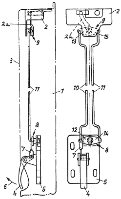
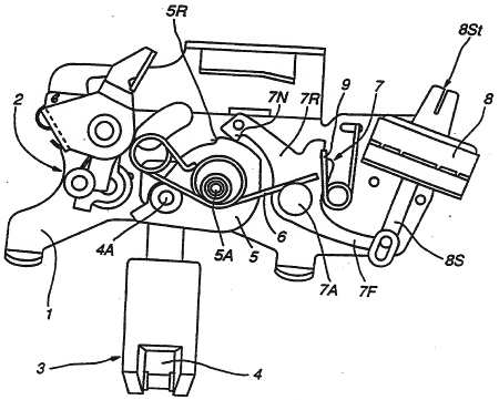
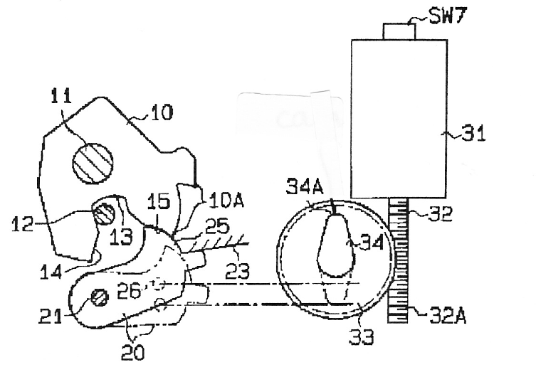
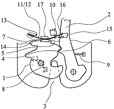
The figure shows another construction, which should avoid actuation at the moment of a collision. Two parallel connecting rods (10, 11) are provided, such that if one of the rods (10,11) would be deformed during an accident, then it could not cause the lever (9) to turn since the second lever (11) would resist this by an equal force acting to turn the lever (9) in the opposite direction.
This place covers:
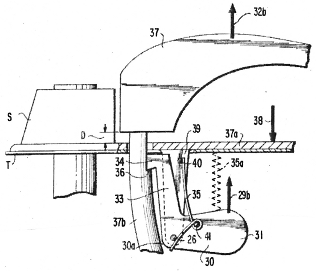
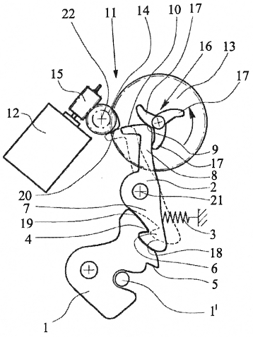
Means for preventing actuation caused by inertial forces acting on lock parts in case of an accident. Typically, a weight arrangement is used, which is actuated in order to block a handle against movement at the moment of collision.
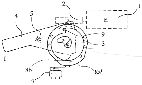
The figure shows an example whereby at the moment of a collision a force (29b) would cause a mass-lever (30) to rotate counterclockwise. A blocking member (34) of the mass-lever (30) thereby prevents the handle (37) to be actuated by an inertial force (32b).
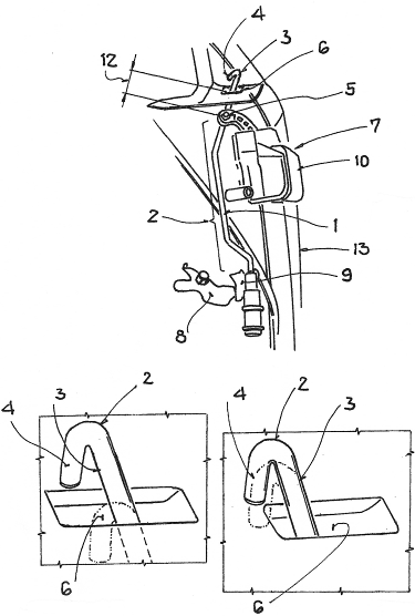
This place covers:
Locks designed for pedestrian protection. In practice, it almost always concerns engine compartment locks (E05B 83/24)
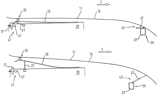
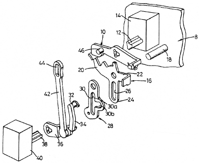
The example in the figure concerns an active front hood system, whereby both the hinge part (41) and the lock (25) are designed such that they are automatically raising the hood (13) in case of a collision with a pedestrian. This allows the front zone of the vehicle to deform easier.
Attention is drawn to the following places, which may be of interest for search:
Arrangements or fittings on vehicles for protecting non-occupants of a vehicle, e.g. pedestrians, in case of accidents |
This place covers:
The general problem that a wing/door is frequently deformed at an accident. In this subgroup the lock is protected in such a way that it can be unlatched/unlocked even if the door is deformed. This is often achieved by protective plates, shields and reinforcements.
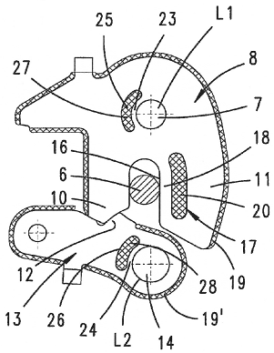
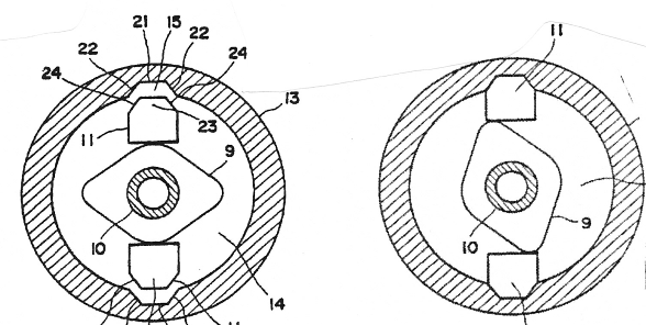
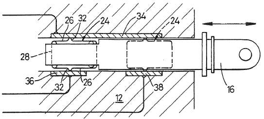
Another alternative is to design lock parts in order to be deformed in a controlled way, such that they can still function after an accident. In the figure the bolt (8) and the detent (13) are provided with deformation zones (17, 25, 26). In case of an accident the bolt and the detent will not break. They will rather be deformed plastically such that they will still function properly after the collision.
This place covers:
Arrangements whereby a particular action is forced to take place in case of an accident. The situation is more or less the opposite of E05B 77/04 in which a particular action is prevented.
A typical example is that a locking or an unlocking action is initiated at the accident. The choice of action depends on the security philosophy. Sometimes an unlocked door, which allows easy escape, is preferred and sometimes the preference is a locked door, which prevents (unwanted) opening of the door.
Another frequent example from this class is locks which after an accident remain locked for a certain time and then automatically move to an unlocked condition.
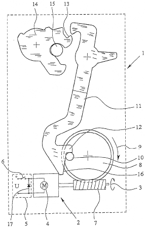
The example of the figure shows a system whereby a sensing means (50) is designed to pivot in case of an accident. This releases the bolt element (26) which is moved by a spring (52) into a striker (56). The door is therefore automatically locked at the moment of an accident.
This place covers:
Locks which usually concern the problem that vehicle keys can be left inside the vehicle, if the door would be accidentally closed in a locked condition.
This place covers:
Locks in which the bolt position is sensed e.g. mechanically, magnetically or electrically. An unlatched bolt should thereby indicate an open door, and in this situation the locking system is blocked in order to make it possible to lock the door only after it has been closed.
The example of the figure illustrates this by a detent (20) having a cam (46) and a locking lever (24) having a shoulder (48).
When the bolt (14) is in its open position, the locking lever (24) cannot move to the locked position, since the shoulder (48) of the locking lever (24) is blocked by the cam (46) on the detent.
This place covers:
Locks where the closing of the door always results in an unlocking action. The lock will thus never be in a locked state after having closed the door. This means that the door can always be unlatched after closing.
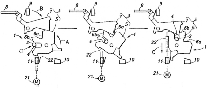
This place covers:
Arrangements whereby the automatic unlocking action can be prevented by overriding means, which require an additional action by the user, e.g. that the door handle is actuated during the closing of the door.
The user can thus decide, that the door should remain locked after closing, but this choice requires that a certain action is carried out during the closing. This makes it less likely, that the door is by mistake closed in a locked state.
According to the exemplifying figures, a lever (60) is actuated by a handle and can be used for unlatching the lock, if a release lever (64) can hit a pin (42) on the detent.
A locking lever (66) can move the release lever (64) to a locked position in which it will not hit the pin (42) as shown in the lower figure. A cam element (92a, 92b) rotates together with the actual latch bolt.
If the lock is brought to the locked position when the door and thereby also the bolt are in the open position, then the closing of the door will rotate the bolt to the latched position. The cam (92b) will therefore act on an intermediate element (94), which brings the locking lever (66) back to the unlocked position.
If however the handle lever (60) is actuated during the closing of the door, then the cam (92b) will not be able to contact the intermediate3 element (94) as shown in the right-hand figure. The lock will thereby stay in the locked position.
This place covers:
Certain functions linked to the inside actuation of locks.
Attention is drawn to the following places, which may be of interest for search:
Sill-buttons, garnish buttons or inside door lock knobs | |
Inner door handles |
Constructional details of the inside actuation means, e.g. inner door handles, sill buttons or lock knobs, are classified in group E05B 85/08 and E05B 85/12.
This place covers:
Essentially the subjects "child safety" and "super-locking/double-locking". Even though the general purpose of preventing an inside handle from being used is the same for these both functions, there is one fundamental difference.
Child safety prevents the use of an inside handle at any time, i.e. the inside handle can never be used regardless if the door is unlocked or locked from the outside. A double-locked/super-locked door has an inside handle, which cannot be used, when the door is locked from the outside.
This place covers:
Locks which prevent all use of an inside handle, when the child safety is activated. This means that the inside handle cannot be used regardless if the door is unlocked or locked from the outside.
The figure shows a child safety arrangement with an actuation button (7) of the push-push type. Every time the button (7) is pushed, the system changes between an active and an inactive state.
This place covers:
Locks having an inside handle, which cannot be used, when the door is locked from the outside. It is therefore not possible to open the door by breaking a window in order to reach the inside handle.
The double-locking can be achieved either by uncoupling or blocking of the inside lock system and inside handle.
In the figure, an example of a blocking system is shown. A double-lock arrangement (9, 12) prevents any actuation of an inside lock knob rod (7).
This place covers:
A combined unlocking and unlatching function of the inside door handle. This is sometimes achieved by one single actuation of the handle. Another possibility is that a first actuation of the handle unlocks the door and that the second actuation unlatches the door.
The figure shows an example of an inside handle (7), which can be moved from a neutral position (A) to an unlatching position (B). If the door would be locked, then the same handle can be moved from the neutral position (A) to an intermediate position (C) and back to the neutral position (A) in order to unlock the lock. The handle can thereafter be actuated one more time to position (C) for unlatching.
This place covers:
Arrangements addressing the well known problem that an unlocking (or locking) action can fail, if the handle of the door is actuated at the same time.
Often a second unlocking action is required. This problem is normally avoided by an energy accumulation arrangement of springs.
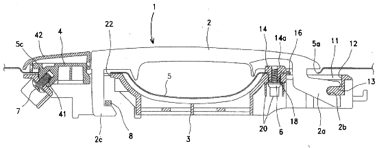
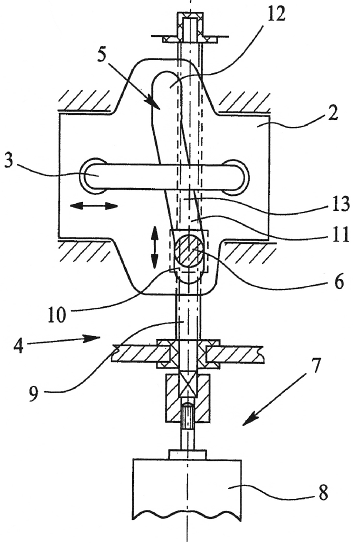
This place covers:
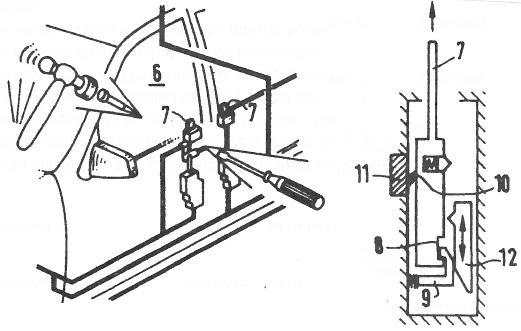
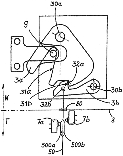
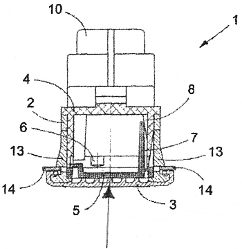
Means offering protection against weather influence. This can for example be achieved by a totally closed lock housing or by arranging some parts of the lock in a "wet compartment" and other parts in a "dry compartment". Another type of weather protection concerns means preventing freezing of the lock in cold conditions.
In the figure, a "wet area" (N) of the lock comprises the main lock elements, i.e. the bolt (3a) and the detent (3b). A sensing arrangement (7a, 7b) for determination of the detent position is housed in a "dry area" (T) o the lock. A single thin link rod (50) extends from the "wet area" to the "dry area" through a small opening (80).
This place does not cover:
Closures or guards for keyholes |
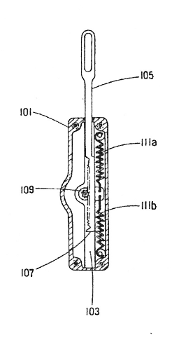
This place covers:
Ways of reducing noise and vibrations in locks. The example in the figure shows a lever element (8) of a lock. The end positions of the lever are defined by stretching of cord elements (3, 3a). The use of cords for this purpose reduces the noise of the lever (8) reaching its end position.
This place covers:
Elastic blocks, elastic guiding elements etc. which are typically placed in the zone of engagement between the bolt and the striker. One function of such blocks can thus be to make an impact between moving elements softer.
Another purpose can be to hold for example a striker firmly fixed in the latched position. This prevents noise due to rattling.
In the figure, an elastic cushion means (30, 40) defines a seat for firmly holding the striker (2).
This place covers:
Bolts, strikers, detents etc. which are covered by a (thin) anti-noise coating/layer. One rather typical example is a metal bolt with a plastic coating.
According to the exemplifying figure, a coating (16) of elastically deformable material allows any direct contact between the base plate (2) of the striker and the bodywork of the vehicle. The noise produced during closing of the lock is thereby reduced.
This place covers:
Arrangements for damping of movements. This class does however not cover elastic blocks/guides (E05B 77/38). It is rather directed to dampers, for example of the fluid type. A typical example is a damper, which slows down the return movement of a handle.
The return movement of the handle in the figure is slowed down by a fluid damper (30).
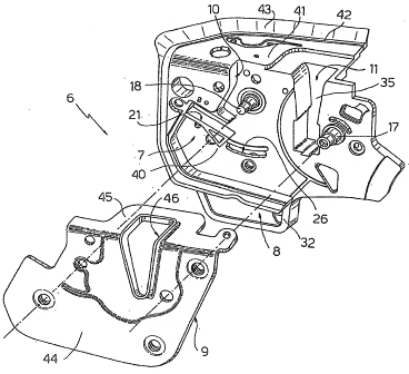
This place covers:
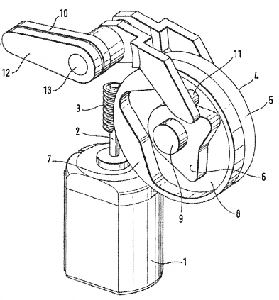
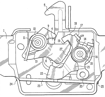
Locks where an arrangement has been provided, which prevents manipulation by burglar tools. Typical examples are protective shields, completely closed casings, or plates which deflect tools away from the essential lock parts.
The figure shows a hollow shield (34) which covers and protects the locking lever (14) and the linkage (20,24) between the locking lever (14) and the lock cylinder (30).
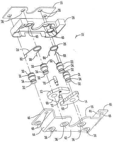
This place covers:
Central locking arrangements. The lower subgroups concern the main families of such arrangements, and the example in the figure therefore shows a more unusual central lock configuration.
A mechanical central lock arrangement uses actuation cables (110,112) for locking/unlocking two doors by a single action performed at one of the two doors.
This place covers:
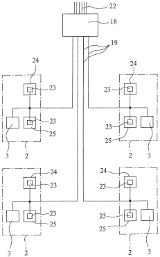
Electrical circuits for control of several locks in a central locking system. This subgroup is essentially directed to the overall electric/electronic circuits for the control of a central door lock system.
In the example each door has an electrically controlled lock module (2), and these four lock module are connected (19) to a central processing and control unit (18)
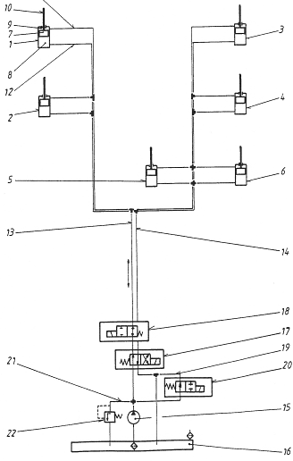
This place covers:
Pneumatic or hydraulic circuits for control of several locks in a central locking system. This subgroup is essentially directed to the overall circuits, as exemplified by the figure wherein a number of actuators (1-4) is controlled by a central control system.
This place covers:
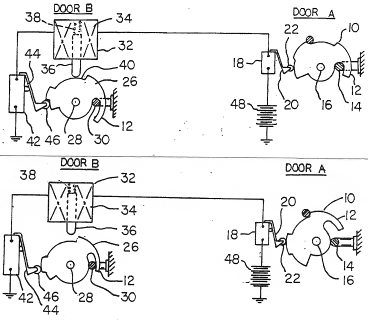
Sequential lock control of a vehicle door system. As shown in the figure, when a first door (A) is unlatched a second door (B) is unlocked, and when the first door (A) is closed and its bolt moves to a latched position, then the bolt of the second door (B) is automatically locked.
Attention is drawn to the following places, which may be of interest for search:
Wings which abut when closed, whereby a fastening for one wing is actuated or controlled by closing the other wing |
This place covers:
Locking of vehicle doors, based on the state of the vehicle systems in general. The state of the door locks could thereby be decided based on for example the speed of the vehicle, the status of the ignition lock, the selected gear or the actuation of the vehicle brakes.
This place does not cover:
Triggered by vehicle collision |
This place covers:
Various aspects of the mounting of lock elements or mounting of the lock itself. It is to be noted, that this subgroup does not cover the connection of movable parts to each other (E05B 79/10).
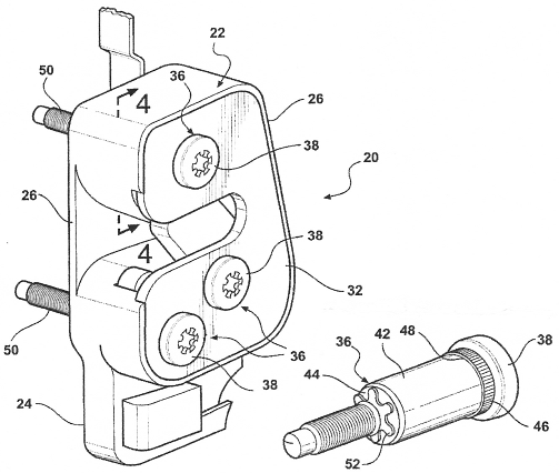
This place covers:
Ways of attaching the lock casing to the vehicle. The casing is thereby often mounted to the wing, but it may also concern the mounting of casings on the fixed frame.
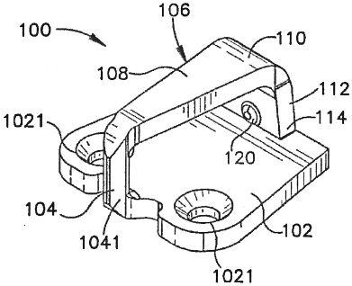
According to the example of the figure, bolt elements (36) are used as axis for e.g. the bolt and the detent of the lock. At the same time these bolt elements (36) have threaded parts (50) which are used for mounting the lock casing (22) to the vehicle.
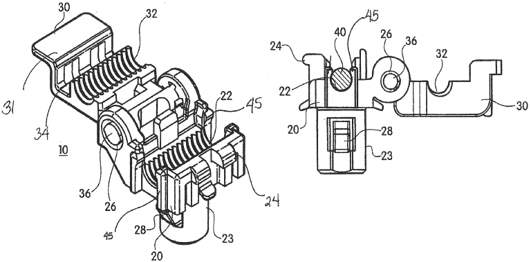
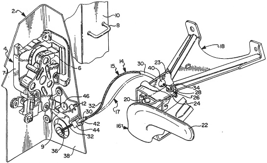
This place covers:
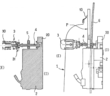
Ways of mounting the handles specific elements in the lock. The figure shows a system using two different screw arrangements (6, 7) for attaching the handle to the wing.
This place covers:
Ways of mounting specific elements in the lock. According to the example in the figure, a specific type of pivot axis (32) is used for mounting the bolt (12) and the detent (14).
This place covers:
Various ways of connecting movable lock parts to each other. The lower subgroups cover he most frequently represented connection aspects.
This place covers:
Elongated connection elements. According to the example shown in the figure a connecting rod (2) is provided with an extension (3) having a hooked end (4). If the door and the rod would be deformed, e.g. due to a collision, then the hooked extension of the rod can cooperate with the edge of an opening (6) such that unwanted operation of the lock occurs.
This place covers:
Ways of connecting rods to each other, as exemplified by a connecting element (40), which links two operating rods (31, 32) to each other.
This place covers:
Details of how connecting rods are fixed to other lock elements. This would usually be the connection to a handle element or to a lever element in the lock housing. It can also concern the details of how a rod is connected to the output member of a powered actuator.
According to the example, a rod clip has one part (23), which is connected to a lever of the lock mechanism, while another part (22,32) connects to an operating rod (40).
This place covers:
Means for guiding long rod elements. In the case of fairly long rod elements it might be necessary to provide guiding means along the length of the rod. This is of particular importance in order to prevent bending of the rod, when it is compressed during a pushing action.
A typical example of such a rod guide (7) is shown in the figure.
This place covers:
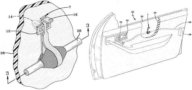
Non-rigid connections between lock parts. Bowden cables are frequently used in these situations, but also wires, ropes or the use of springs as connection means are covered by this subgroup.
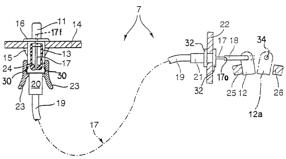
The figure shows a specific type of Bowden-cable connection, whereby a cable (32) is fixed at one end (36). Tensioning the cable (36) will therefore cause the sheath to be straightened and thereby push on a lever (12) of the lock.
Attention is drawn to the following places, which may be of interest for search:
Flexible shafts; … Mechanical means for transmitting movement in a flexible sheathing |
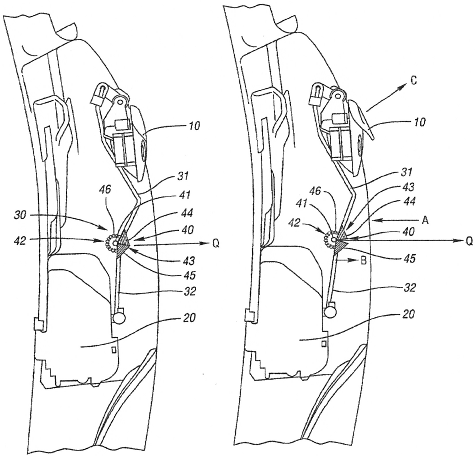
This place covers:
Details of how hand actuated elements are connected to lock elements. It is to be noted that E05B 79/12 and E05B 79/20 quite often will cover the connection of handles to a lock situated at a distance more or less far away.
This subgroup will consequently for example cover operative, i.e. movable, connections where a handle is more or less directly fixed to the lock. Other elongated connections than rods or flexible elements will also be covered by this subgroup.
This place does not cover:
Mounting of the non-movable base elements of a handle to a lock |
In this place, the following terms or expressions are used with the meaning indicated:
latching/unlatching | holding/release of a bolt element that a wing or door can be opened. A typical vehicle lock is unlatched when a detent, pawl or ratchet releases the fork shaped bolt |
locking/unlocking | preventing/allowing an unlatching action. In the locked state an unlatching action, normally done by actuating a handle or grip, is prevented. A locked door or wing is at least prevented from being unlatched from outside of the vehicle |
This place covers:
Various types of actuators, whereby the most common alternatives are covered by the lower subgroups.
One example of a less common power driving means is shown in the figure, which shows a pyrotechnic charge (10) provided for bringing a bolt (4) or a connecting rod (24) to an unlocked position in case of an accident.
This place covers:
Actuators driven by electricity. The figure shows a lock with a handle (3), which can release a bolt (2) from a striker (6). The bolt (2) can also be released by electrically heating a shape memory alloy actuator wire (9). This heating shrinks the actuator wire, and the bolt (2) will consequently be released from the striker (6).
This place does not cover:
Electrical circuits |
This place covers:
Electrically driven motors, as exemplified by the motor (2) of the figure.
This place covers:
Electromagnets or solenoids, most often of the linear type. However, as the figure exemplifies, also rotary electromagnets (10) are used for vehicle lock actuation.
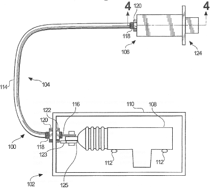
This place covers:
Actuators of the hydraulic or pneumatic type. In the figure, a pneumatic actuator (8) is used for powered actuation of a boot lid lock.
This place does not cover:
Hydraulic or pneumatic circuits |
This place covers:
Various ways of using an actuator in a vehicle lock. These uses are thereby in principal defined depending on which lock part(s) the actuator is connected to.
This place covers:
A typical vehicle lock comprises a fork-shaped rotary latch bolt, which is kept in its latched position by a detent. In this subgroup the power actuator releases the detent of the bolt and consequently an unlatching takes place. The result of the powered actuation is thus that the door is free to be opened.
The figure shows an actuator (12), which drives cam elements (17) through a geared transmission. The cam elements (17) act on a detent (2) in order to unlatch the bolt (1).
This place covers:
Actuators which achieve the movement of a locking element (typically a locking lever) between a locked and an unlocked position.
The actuator consequently moves the lock between an unlocked state wherein the bolt is allowed to move and a locked state in which the movement of the bolt is prevented.
The movement of the bolt is thus not directly influenced by the actuator. A very common example in this subgroup is the powered locking/unlocking of central-locking arrangements.
According to the figure, a locking lever (10) is pivotally mounted on the output axis (12) of an actuator (14). The locking lever (10) can be moved between a locked and an unlocked position by means of the actuator (14).
This place covers:
Actuator acting on the bolt in order to move it, normally from a position in which it holds the door closed to a position in which the door can be opened, or vice-versa. It could thereby concern both latch bolts and dead bolts.
The figure shows an actuator (108), which drives a lock bolt (124) between a locked and unlocked position.
Attention is drawn to the following places, which may be of interest for search:
Adaptation of locks, latches, or parts thereof, for movement of the bolt by electromagnetic means |
This place covers:
Pulling the door tight or pushing the door slightly open. It is to be noted, that this subgroup covers the cases where these (small) movements of the door are achieved by the lock. This should not be confused with the powered closing /opening of for example E05F 15/00, where the wing is moved from a (more or less) open position to a (more or less) closed position.
The example illustrates this by an actuator (21), which uses a pushing element (22) in order to assist movement of a bolt from a half-latched to a fully-latched position.
This place covers:
A movable striker for achieving the final closing or the initiated opening. A typical example is that after a first engagement between a striker and a bolt, the striker is moved by an actuator in order to further pull the wing tight.
The exemplifying figure shows an actuator in the form of an electric motor (8). When an axis (9) is turned by the motor (8), a pin (6) moves in an inclined slot (5) of a striker base (2). The actual striker (3) can thereby be driven by the motor (8) for assisting the movement of the door to a fully closed position.
This place covers:
Various individual aspects of actuator details and transmission constructions.
This place covers:
Different types of actuator output elements. It thereby essentially concerns the final element in the kinematic chain of the actuator device. Such an output element is then typically connected to elements of a vehicle lock, either directly or via further connecting means. The lower subgroups E05B 81/28 and E05B 81/30 relate to the two most common types of output members.
This place covers:
Output elements which move linearly, as exemplified by the sliding output member (105) in the figure.
This place covers:
Output elements which rotate, as exemplified by rotatable output members (10,12) which both rotate around axis (13) in the figure.
This place covers:
Various elements in the kinematic chain before the actuator output member. Different typical kinematic elements are the subject of the lower subgroups E05B 81/34 – E05B 81/46.
This place covers:
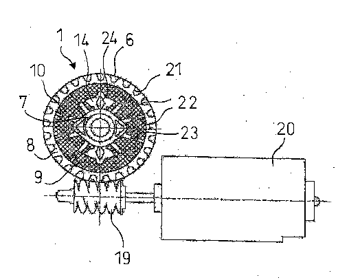
Geared elements in the kinematic chain of the actuator, as exemplified by the toothed gear elements (8) which are driven by the worm-screw (19).
This place covers:
Elements in the shape of a sector with gears on its outer rim. An example of such a sector (10) is shown in the figure.
This place covers:
The use of planetary gear transmission in actuators, as exemplified by the figure.
This place covers:
Transmissions of the type where a nut-like element (6) slides along a threaded rotating axle (4) as exemplified by the figure.
This place covers:
Cam-like transmission elements, for example a motor driven cam (34), which is used for transmitting a movement to elements of the actual lock.
This place covers:
The use of the contour of a groove as cam element for transmission of a movement, as exemplified by the groove (3) in the figure.
This place covers:
Transmissions comprising some kind of engagable/releasable clutch arrangement. In the figure, a clutch element (23) engages a groove (21) in a driven element (13), when a motor driven element (9) starts rotating.
This place covers:
Actuators moving only in one direction. From a starting position, the actuator moves continuously in one step or in several steps, always in the same direction, until it arrives back at the starting position again.
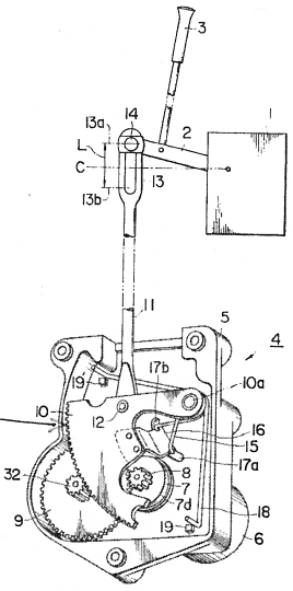
One example can be seen in the figure, where the motor (2) and the actuating element (8) can only turn in one direction (3,9). An electric arrangement (17) is provided for minimizing the back-drive when the drive pin (10) hits an abutment stop (12). When the detent pawl (11) has moved further clock-wise, then the actuator can continue to move in its single driving direction (3,9).
It is to be noted, that essentially the whole movement cycle should be power actuated. If for example a significant part of the movement is achieved by e.g. a mechanical spring, then the subgroup E05B 81/50 takes precedence.
This place covers:
Actuators which are power driven to move from a neutral position to an active position, and the return movement to the neutral position is provided by non-powered means.
Examples of such arrangements can for example be a linearly moving solenoid, whereby an output member is moved electro-magnetically from a neutral position to an active position. When the power later is cut, a spring is arranged for moving the output member.
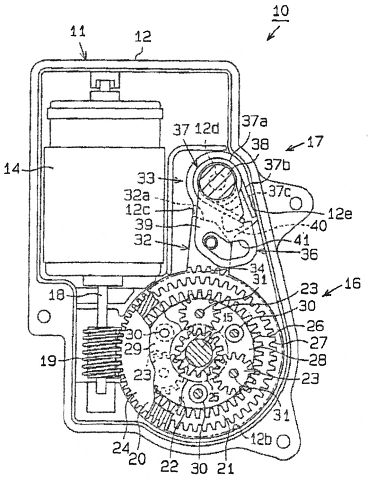
In the figure a geared transmission is moved by powered means to an active position. At the same time a geared rack (130) is moved, and this compresses spring (146). When the power is cut, the accumulated energy of the compressed spring (146) moves the rack (130) in the opposite direction such that the actuator returns to its normal position.
This place covers:
Hydraulic or pneumatic circuits of vehicle locks. This subgroup concerns the overall circuits (pipes, valves pumps etc.) providing pressurized fluid to the actuators, while the structural elements of hydraulic/pneumatic actuators can be found in E05B 81/10.
In the figure a typical example of a circuit in the sense of the present subgroup can be seen.
This place does not cover:
For locking several wings simultaneously |
This place covers:
Electric circuit schemes and individual circuit components. The lower subgroups concern a variety of specific control methods, monitoring, sensing and energy supply. This subgroup will consequently contain e.g. electrical circuits not covered by the various lower subgroups.
This place does not cover:
Electric circuits for controlling plurality of locks on different doors |
This place covers:
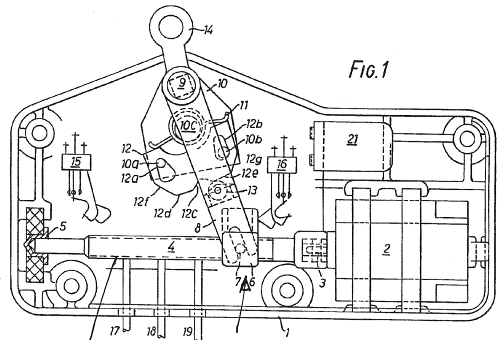
Various ways of controlling the way in which an actuator works. The most common control methods can be found in the respective lower subgroup. This means, that this subgroup will for example contain electrical circuits in cases which are not covered by one of the specific lower subgroups. An example of such a circuit is given in the figure, whereby an electrical control circuit (6) is provided in order to control the power input to the motor connectors (9,10).
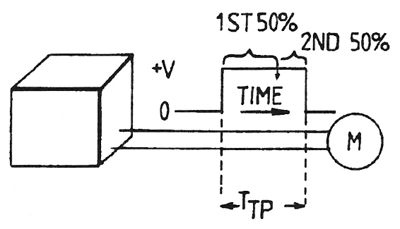
This place covers:
The use of time data for the control of actuators. In the example of the figure, a switch indicates when 50% of the actuator stroke has been completed. The time needed for this first half of the stroke is measured and used in order to calculate how much run-time will be needed for achieving the second half of the stroke.
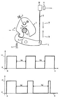
This place covers:
Control of actuators by pulses e.g. of varying length and frequency. One way of providing such control is shown in the figure, whereby the pulse-width for operating the actuator to release the detent (4) from the bolt (1) is different from the pulse-width used for bringing the detent (4) back to the initial position.
This place covers:
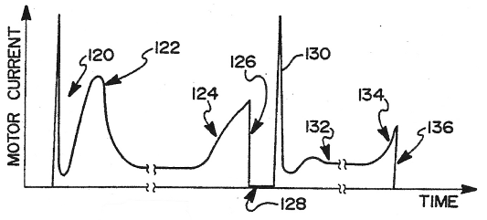
The use of electrical parameters for actuator control. A typical example of such a controlling method is to detect an increase of the current when an end position is reached, as exemplified by the figure wherein a current increase (124) is detected for stopping the movement of an actuator in one direction and a subsequent current increase (134) causes the stopping of the movement in the opposite direction.
This place covers:
Detection of lock states or user input by sensing/monitoring positions of various lock elements.
This place covers:
Monitoring of the lock status by sensing the bolt position. In the exemplifying figure two switches (55,57) are used for indicating the position of the bolt (17.
This place covers:
Control of the lock status by sensing the detent position. In the figure, a sensor (10) detects the position of the bolt as well as the position of the detent.
This place covers:
Indication of the closure status by sensing the door position. It should be noted, that the sensors for door position should be part of the lock or at least related to the function of the lock. An example of a lock monitoring system, which uses the detection of the door position is shown in the figure.
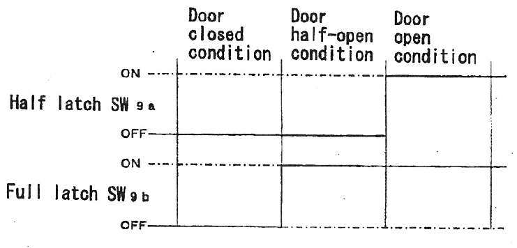
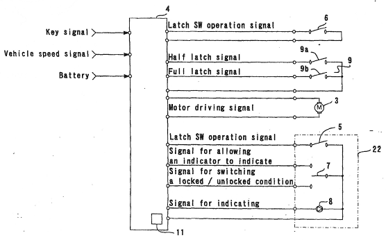
This place covers:
Lock monitoring by sensing a locked/unlocked condition. In the figure, such a monitoring is performed by a switch (7).
This place covers:
A special case of sensing the lock status via the state of the actuator. The figure shows such an arrangement, whereby a protrusion (32) comes into contact either of the two plates (36,38). This closes an electrical circuit, which indicates the state of the actuator and this is then used for indication of the lock status.
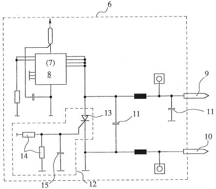
This place covers:
Handles with some kind of electrical function. It first of all concerns handles working more or less as an electrical switch. The handle does thus not perform any mechanical action on the lock. It is simply a switch for sending a signal (e.g. by closing a circuit) to the lock-electronics.
This subgroup also covers handles, which perform both a mechanical function as well as an electric function.
An example of a switch- type handle is given in the figure. This shows an opening switch for vehicle doors or trunks, which is actuated by pressing the cover element (3) in the direction of the arrow.
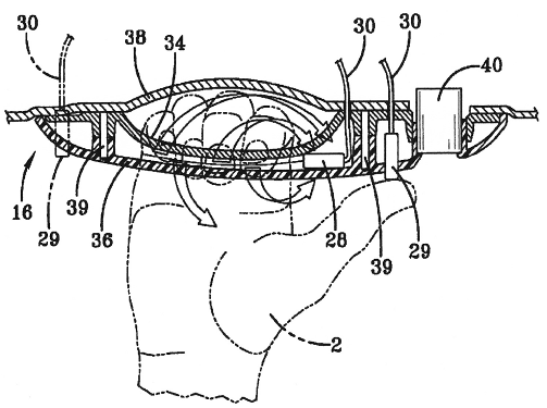
This place covers:
Handles used for the initiation of a hands-free opening. A sensor or switch in or near the handle starts the data transfer. This could be done either by moving the handle in a predetermined way or by a proximity sensor, which registers the approach of a hand towards the handle.
It should be noted that this class does not concern the details of the coded data transmission between the lock and a transponder key.
According to the example in the figure, two switches (28,29) can be sensed/actuated by different actions of a user's hand for example in order initiate a hands-free opening process.
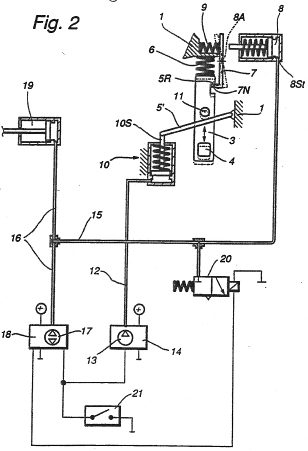
This place covers:
Various kinds of energy sources (other than the vehicle main battery) and spare-power devices.
If the main power source is defect (for example because the main battery of the vehicle is empty), then these power sources can provide a small amount of power for an emergency opening of the vehicle. This section also covers cases where the primary energy source is not the vehicle main battery. This would for example sometimes be the case for certain types of battery charged locks.
This place covers:
Additional batteries or back up batteries used for example in case of failure of energy supply from vehicle main battery.
This place covers:
Generators operated by the vehicle user. Such generators can be adapted for supply of energy for example by handle movement, opening/closing of the door or introduction of the key into the keyhole. The figure shows a generator (22), which supplies energy for the operation of the actuator (17) when the voltage of the main battery is below a certain level.
This place covers:
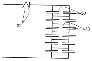
The use of capacitors for provision of energy for example when the main battery has been discharged. The figure shows a number of supercapacitors (30) which are available as a back-up energy source. A diode (32) or similar component prevents discharge of the supercapacitors (30) into the main power supply means.
This place covers:
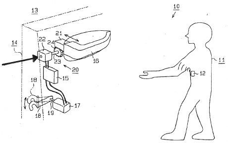
The use of induction for provision of energy. This can be used in situations when it is desired to avoid cables and contacts. One example of this type of arrangement is the provision of a coil in the key another coil in the lock for non-contact supply of emergency power to the lock.
This place covers:
Purely mechanical manual override means. One example would be a door handle, which in normal use electrically activates an actuator. In case of a power failure this handle can be actuated further or in another direction in order to actuate the lock mechanically.
This subgroup also covers cylinder locks in normally not visible, concealed positions. In the figure, a cylinder lock (9) is for example mounted behind the rear-view mirror (1).
It is to be noted, that this subgroup does not cover normally visible, non concealed cylinder locks mounted in or near the door handle.
This place does not cover:
Locks specially adapted for bicycles | |
Locking arrangements for non-fixed roofs | |
Latching means for sideboards or tailgates of open load compartments |
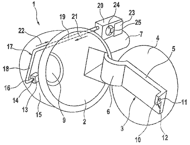
This place covers:
Locks for commercially used vehicles.
One specific subject, covered by this and the lower subgroups, is locks for (standardized) freight containers for use on trucks and trains, but also on ships or in aircrafts.
This subgroup consequently covers locks both for load compartments that form an integral part of the vehicle as well as freight containers forming a removable part which can be separated from the vehicle.
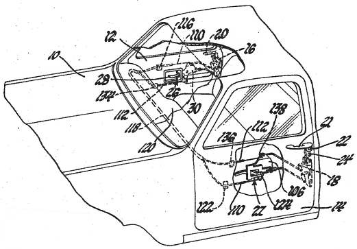
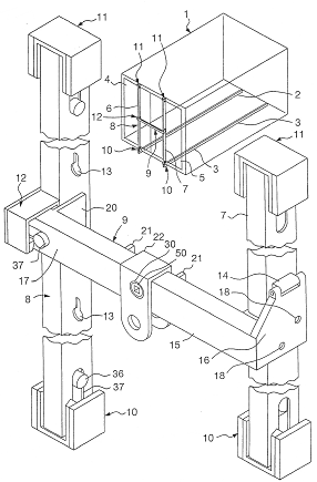
The figure shows a lockable structure applied to a container (1). In the locked position three bars (7, 8, 9) form a cross-bar construction preventing the doors (4, 5) of the container (1) to be opened.
This place covers:
Locks for sliding wings on commercially used vehicles. The figure shows an example of a hook bolt (34) for locking a sliding roll-up door (16).
This place covers:
Locking arrangements for railway freight cars, as exemplified by the figure where the locking device (20) keeps the sliding door (12) closed.
This place covers:
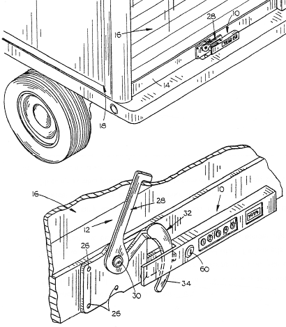
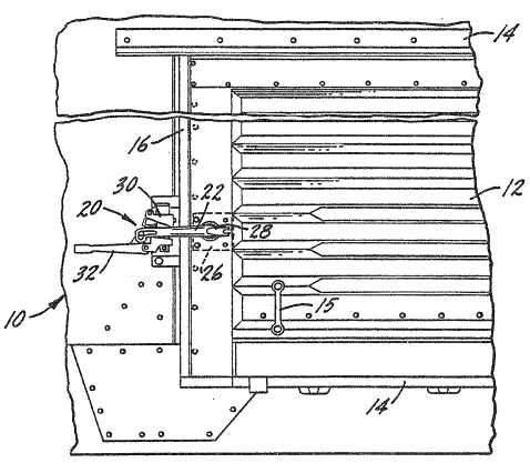
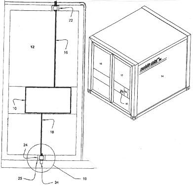
Locking devices with actuation bars which usually connect actuation means, for example a handle, with a fastening means. The figure illustrates this by showing a central actuation unit (10) connected to fastening means (22) by sliding bars (16).
This place covers:
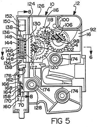
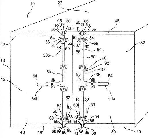
A very common locking arrangement for cargo vehicles with rotary bars connecting for example a handle and lock bolt(s).
In the figure the rotary bars (50a, 50b) are actuated by handles (64a, 64b) in order to move fastening means (66,68) between a locked and unlocked position.
This place covers:
Smaller locks for vans (e.g. delivery vans, plumber's van, locksmith's van). These vans usually have doors with locks, which are similar to locks for passenger doors, but quite often adapted to the special requirements needed for the various commercial purposes of the van.
The example of the figure discloses a lock for use on a door between the driver compartment and the cargo compartment.
This place covers:
Lock devices with means indicating authorized or unauthorized actuation of the lock device.
In the figure, the handle (143) of a hook bolt locking device is sealed by a wire (189) which has to be broken when the handle is to be actuated.
Attention is drawn to the following places, which may be of interest for search:
Locks giving indication of unauthorised unlocking | |
Security seals |
This place covers:
Lock devices for non-passenger compartments essentially located at the outside of the vehicle.
In most of the cases the rear compartments are used for load purposes, e.g. for luggage. This also covers locks for luggage compartments of hatchback/station (family) cars.
At the front of the car it usually concerns a hood for the engine compartment.
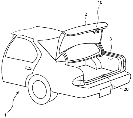
This place covers:
Locking arrangements for boot lids and luggage compartments, normally at the back of a car. A typical example of this subgroup is shown in the figure, whereby a lock (10) cooperates with a striker (20) for holding the boot lid (2) closed.
This place covers:
Locking arrangements for luggage compartments with more than one wing. One example of such a lock system is shown in the figure.
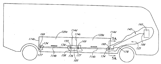
This place covers:
Locking arrangements for luggage compartments at the side of the vehicle, as exemplified by the figure, which shows a recreational vehicle with a central actuator (160) for locking and unlocking of several luggage compartment doors at the vehicle side.
This place covers:
Locks for compartments at the front of a vehicle. These locks are normally provided with a primary and secondary bolt in order to obtain a double security. This assures that the wing stays closed even if the primary bolt fails.
In the figure a striker (4) is held in the latched position by a primary bolt (8). A secondary bolt (5) catches the striker (4), if the primary bolt (8) would fail.
This place covers:
Arrangements for allowing escape from the inside of a boot. There are normally no means for actuating the boot lock from the inside.
This subgroup concerns means allowing operation from the inside in case of emergency. In the figure a handle (12) is provided for emergency opening.
This place covers:
Locks for storage compartments located in the dashboard area in front of the passenger seat. An example of such a device can be seen in the figure.
This place covers:
Locking arrangements for storage compartments normally placed between passenger seats as exemplified by the figure.
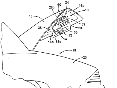
This place covers:
Locks for fuel inlet covers, which essentially lie in the plane of the vehicle surface, when closed. In the figure a fuel inlet (9) is covered by a lid (4). An actuator (20) drives a bolt (16) between a locked and unlocked position. The caps which actually close the inlet pipe in a fluid-tight way (with or without lock) and the flush cover flaps, per se, are rather covered by B60K 15/04 and B60K 15/05
Attention is drawn to the following places, which may be of interest for search:
Fuel inlet covers, as such |
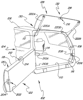
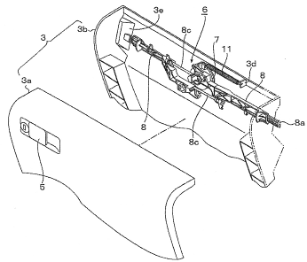
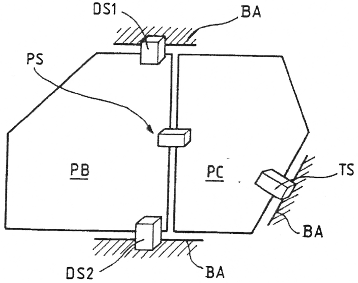
This place covers:
Locks for door arrangements without a central post between the front and the back door. According to the exemplifying figure a pivoting door (PB) and a sliding door (PC) are kept in a closed position by a system comprising four different locks (DS1, DS2, TS, PS).
This place covers:
Locking devices for sliding passenger doors. The example in the figure shows a lock system for a sliding door (D). It comprises a rear latch mechanism (11), a front latch mechanism (13) and a lower latch mechanism (17).
This place covers:
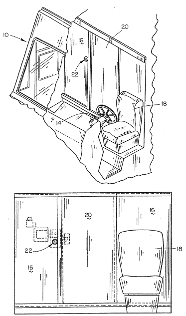
Locks for passenger compartments of large commercially used vehicles. The figure shows a cabin (1) of a working vehicle. On the inside of the cabin door a handle (24) can be operated for releasing a door lock mechanism (22).
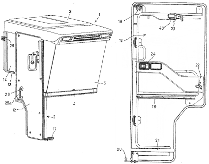
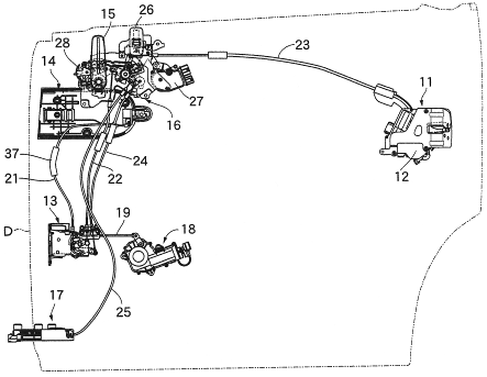
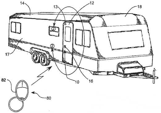
This place covers:
Locks for campers, caravans and similar. One commonly addressed problem is to secure the doors from the inside during night.
The figure is directed to a lock for a caravan, which can be locked and unlocked with a remote control (82).
This place covers:
Housing structures for vehicle locks as exemplified by the figure, which shows a housing (6) composed of a plastic shell (7) and a metallic plate (9).
Examples of places in relation to which this place is residual:
Mounting of lock casings |
This place covers:
Elements cooperating with the bolt for holding a wing closed. These striker elements are also called keepers. They are normally constructed as a pin or a staple for cooperation with a bifurcated latch bolt. A typical example is shown in the figure.
This place covers:
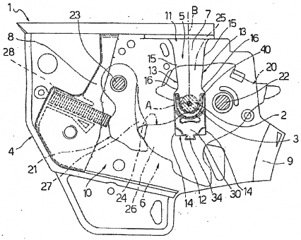
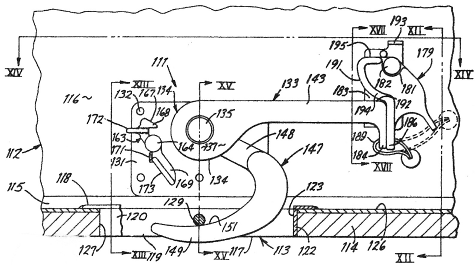
Arrangements of lock cylinders in vehicle lock devices. A usual subject of this subgroup is the connection between a lock cylinder and the lock mechanism in a lock housing. Such a construction is disclosed in the figure, wherein a lock cylinder (30) is connected to a lock mechanism (20) by means of a particular rod (4).
Attention is drawn to the following places, which may be of interest for search:
Devices for coupling the turning cylinder of a single or double cylinder lock with the bolt-operating member |
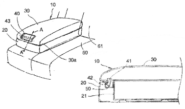
This place covers:
Buttons or knobs on the inside of the door for locking/unlocking of the door. It usually concerns either a sill-button placed on the door trim near the window or a knob/button placed near or in the door handle unit. The figure gives an example of a sill/garnish button (11) arranged for actuation of a locking lever (12).
Attention is drawn to the following places, which may be of interest for search:
Functions related to actuation of locks from the passenger compartment of the vehicle |
This place covers:
Various types of vehicle door handles for actuation of locks. The lower subgroups concern the most common groups of such handles.
This place does not cover:
Mounting of handles | |
Operative connections of handles |
This place covers:
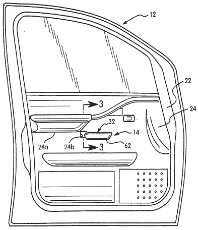
Handles on the inside of the door as exemplified by the figure, in which a door handle (32) is provided for actuation of the door lock.
This place covers:
Pivoting handle constructions with an axis essentially parallel to the plane of the wing. This is a very common type of handle movement, and the lower subgroups concern the most usual basic concepts. The example figure of this subgroup therefore discloses another type of such a pivoting handle.
This place covers:
One of the two most commonly used vehicle handle constructions. The figure illustrates how a longitudinal handle (1) pivots at one end (4) around an axis perpendicular to the longitudinal direction of the handle.
This place covers:
The second of the two most commonly used vehicle handle constructions. The figure illustrates how a longitudinal handle (16) pivots around an axis (27) parallel to the longitudinal direction of the handle.
This place covers:
Details of locking elements in the form of e.g. latch-bolts or dead-bolts and detents for such bolts. A vehicle front hood lock comprising a bolt (2) with a combined rotational and sliding movement, as illustrated by the figure, would belong in this subgroup.
This place covers:
Vehicle locks with sliding bolts as illustrated by the figure, in which an actuator (18) causes a sliding movement of a bolt (22).
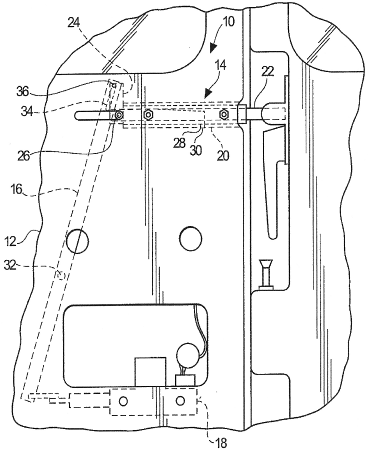
This place covers:
Vehicle locks with pivoting bolts. The vast majority of pivoting bolts in vehicle locks is of the bifurcated type. The example of the figure therefore shows a more unusual form of pivoting bolt. The striker (5) is guided onto a centering pin of the lock housing, when the door is closed. A hook element (3) of the bolt (2) will thereby come in contact with an edge (4) of the striker (5). The pivoting bolt (2) is held in the latched position by two detents (6, 10).
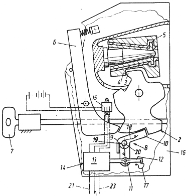
This place covers:
Cases where the detent, the bolt or the way in which they cooperate is described. In the figure a bolt (2) and a detent (3) are provided with contact surfaces with specifically chosen curvatures.
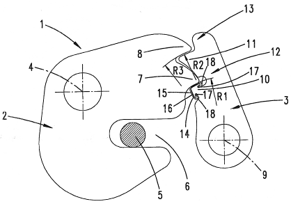
This place covers:
Bolt members shaped as toothed wheels. This used to be a very common bolt/striker construction but is rather unusual nowadays.
The lock in the figure has a wheel shaped bolt (21) with toothed elements (14) which cooperate with a protrusion (35) on the striker for holding the wing closed.