CPC Definition - Subclass B66C
This place does not cover:
Devices for lifting patients or disabled persons | |
Toy cranes | |
Devices for carrying objects by hand |
The following IPC groups are not used in this classification scheme.
Subject matter of these groups is classified in the following groups:
IPC B66C23/61 classified in B66C 23/60
IPC B66C23/683 classified in B66C 23/68
IPC B66C23/687 classified in B66C 23/701
IPC B66C23/69 classified in B66C 23/701
IPC B66C23/693 classified in B66C 23/705
IPC B66C23/697 classified in B66C 23/707
The scheme includes entry B66C 23/54, for which no corresponding IPC exists. Subject matter should be given an IPC classification in B66C 23/68
Documents should be classified in the lowest subgroup possible and only classified in higher groups if none of the subgroups is applicable. If necessary documents should be classified in multiple subgroups. All non-trivial technical features should be classified. Main groups should only be used when no appropriate subgroup exists.
This place does not cover:
Work holders | |
Robots with suction lifting devices | |
Feed or transfer devices | |
Conveying fragile sheets | |
Separating articles from piles | |
Suction cups for attaching purposes |
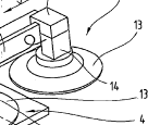
This place covers:
See for example US2007/0130884
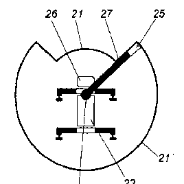
This place covers:
suction means with a circular shape
See for example EP 1 775 243
This place covers:
Arrangements for ensuring correct vacuum level or preventing load from falling if vacuum is lost.
This place covers:
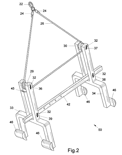
Devices where the weight of the load is supported by the operator.
See for example US 2 212 755
Also classified in B65G 7/12
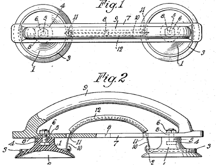
This place covers:
Devices where the edge of the suction cup has a particular arrangement, for example a shape.
See for example US 1 426 930
This place covers:
This group not used, devices classified in following two subgroups.
This place covers:
Devices where the suction cups are separated from each other by the mounting and/or piping arrangement.
See for example US 1 426 692
This place covers:
Devices where the suction cup is a single unit with separated vacuum areas.
See for example EP 1 118 578
This place covers:
General control arrangements not covered by the following three subgroups.
This place covers:
Devices for rotating the load being lifted.
See for example US 4 696 613
This place covers:
Devices where the vacuum is created using venturi or bernouilli principle.
See for example GB 1 396 737
This place covers:
Devices where the action of lifting the device creates the vacuum between the load and the suction cup.
See for example US 7 543 868
This place covers:
suction means with a rectangular shape
See for example US 3 506 297
This place covers:
Shapes which are neither circular nor rectangular or are non-planar.
See for example US 4 084 306
This place covers:
Devices with only a single vacuum area.
See for example US 4 413 853
This place covers:
Lifting devices with permanent magnets.
This place does not cover:
Work holders | |
Robots with magnetic lifting devices | |
Feed or transfer devices | |
Separating articles from piles | |
Lifting devices with both electromagnets and permanent magnets |
Attention is drawn to the following places, which may be of interest for search:
Permanent magnets for lifting or picking up |
Attention is drawn to the following places, which may be of interest for search:
Electromagnets for lifting or transporting magnetic material |
This place covers:
mechanical load engaging devices not covered by one of the following subgroups
See for example US 5 800 000
This place covers:
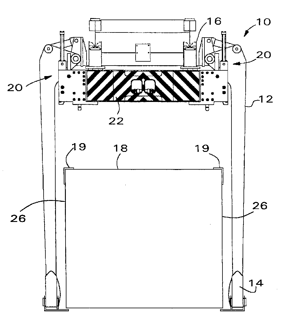
Lifting devices for containers.
See for example US 2008/0292440
This place does not cover:
Connectors, e.g. twistlocks, for connecting a lifting device to a container |
This place covers:
See for example US 2009/0278368
This place covers:
See for example EP 1 857 401
This place covers:
Devices where the load support is not directly under the crane hook, to allow the load to be deposited to one side.
See for example US 7 017 963
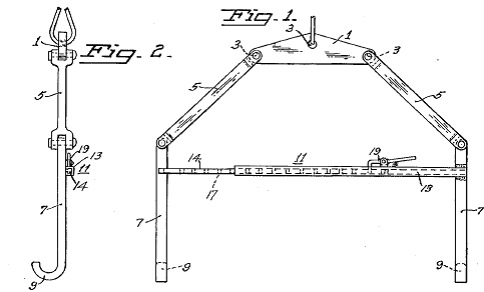
This place covers:
Load supporting devices for lifting engines.
See for example US 3 995 903.
This place does not cover:
Manually movable cranes for lifting engines |
This place covers:
Load supporting devices for wind turbine parts.
See for example US 2009/0025219.
This place does not cover:
Cranes for lifting wind turbines |
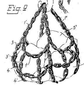
This place covers:
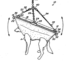
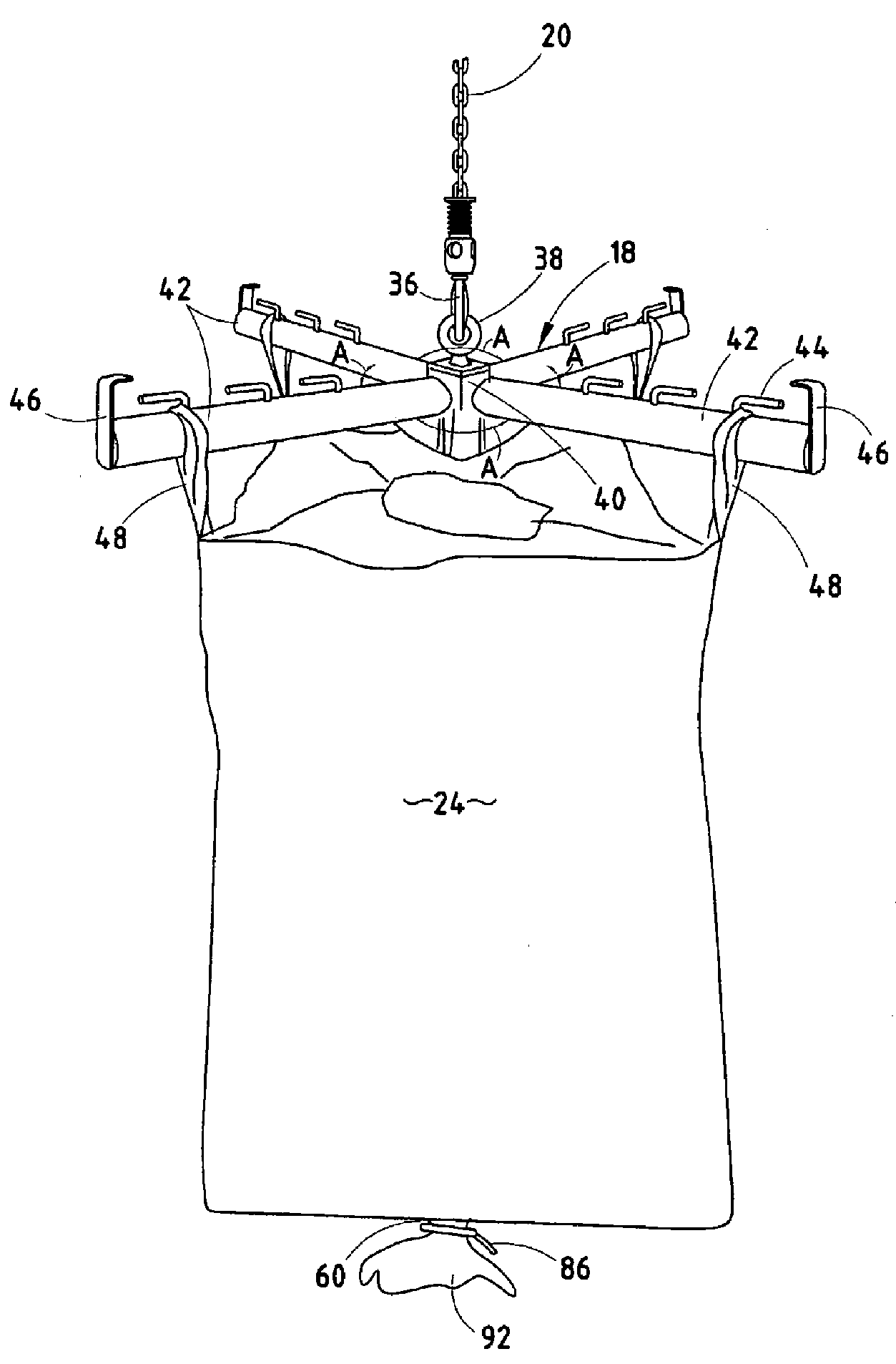
Slings not covered by one of the following subgroups.
Devices where a sling is suspended from a platform.
This place covers:
Devices for protecting the sling from damage.
See for example US 4 039 218
This place does not cover:
Devices for protecting the load |
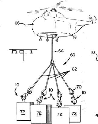
This place covers:
Lifting chains connecting the load to the lifting device
See for example US 2 989 287
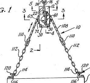
This place covers:
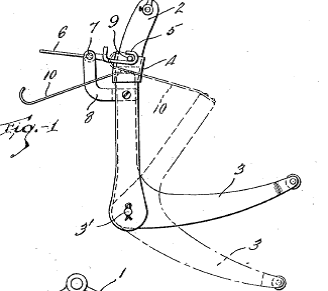
Chains or slings with hooks to attach to load.
See for example US 4 017 111
This place does not cover:
Chains with hook for attaching to chain link to form a loop around load | |
Devices for lifting barrels |
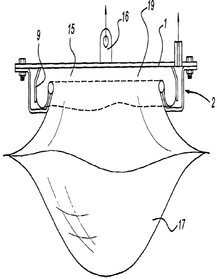
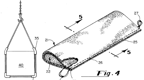
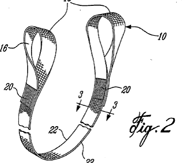
This place covers:
Slings with a flat cross-section.
See for example US 2008/0277952
This place does not cover:
Straps for attaching loads e.g. to trucks | |
Construction of cables or slings |
This place covers:
See for example US 4 232 893
This place covers:
See for example US 3 010 751
This place covers:
Rigid lifting devices for lifting a container from below
See for example US 5 649 805
This place does not cover:
Lifting (e.g. from above) using twistlocks |
This place covers:
See for example US 2005/0199650
This place covers:
See for example US 2006/0175850
This place covers:
See for example US 1 777 119
This place covers:
See for example US 5 066 189
This place covers:
See for example US 3 001 812
This place covers:
See for example US 2 670 985
This place covers:
See for example US 2009/0049663
This place covers:
Hooks where the load is automatically released when the load is lowered.
See for example US 5 292 165
This place does not cover:
Non-automatic release arrangements |
This place covers:
Load measurement on the hook.
See for example US 2010/0037700
This place does not cover:
Load measurement elsewhere on crane |
This place covers:
Gripping members not relying on friction to hold load, e.g. where the shape of the device ensures sufficient hold.
This place does not cover:
Gripping members for particular articles |
This place covers:
See for example US 5 842 729
This place covers:
See for example US 2 226 789
This place covers:
Devices using fluid motors or cylinders.
This place covers:
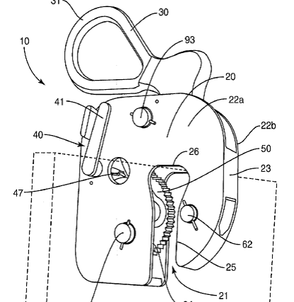
Gripping members relying on friction to hold load.
This place covers:
See for example US 5 280 982
This place covers:
See for example US 5 209 536
This place covers:
See for example US 4 253 696
This place covers:
See for example US 3 695 670
This place covers:
See for example US 5 158 416
This place covers:
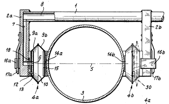
devices gripping drums or barrels either by their body or edges
See for example US2010/0140968
This place covers:
See for example US 4 371 203
This place covers:
Devices such as lifting rings or pins lifting via holes in object being lifted
See for example US 7 014 230
This place covers:
Devices such as twistlocks, which connect a lifting device to a container
See for example US 2004/0256266
This place does not cover:
Lifting devices per se such as spreaders for containers | |
Lifting from below container |
This place covers:
See for example US 4 634 164
Attention is drawn to the following places, which may be of interest for search:
Anchors in concrete elements |
This place covers:
lifting devices mounted on a rigid arm, boom, jib etc. rather than suspended from a flexible element such as a cable or chain
See for example US 2009/0245989
This place covers:
See for example US 2006/0086685
This place covers:
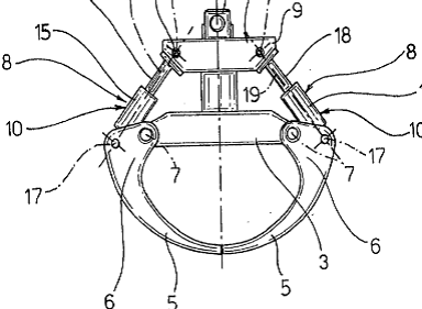
Devices where a single rope is used for both raising and subgroupsering and opening/closing.
See for example US 5 649 729
This place covers:
See for example US 4 807 918
This place covers:
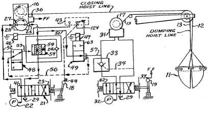
Devices where separate ropes are used for raising and subgroupsering and opening/closing.
See for example US 4 328 987
This place covers:
Grabs operated other than by electric or hydraulic motors, e.g. magnets
See for example US 6 179 357
This place covers:
See for example US 2009/0250887
This place covers:
See for example US 7 503 460
This place covers:
See for example US 4 106 641
This place covers:
See for example US 5 593 050
This place covers:
See for example US 4 762 240
This place covers:
See for example US 2008/0237174
This place covers:
See for example US2002/0014568
This place covers:
Details of rails, mountings, suspension etc.
See for example US 3 335 955
This place does not cover:
Devices for underhung trolleys |
This place covers:
Extension parts with different section.
Extensions pivoted to or telescoped in end of track section.
See for example US 2006/0260502
This place does not cover:
Similar track sections joined to each other |
This place covers:
Devices on rails for allowing transfer.
See for example US 2003/0140816
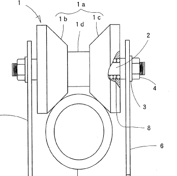
This place covers:
Trolley suspension arrangements
See for example US US2011/0076125
This place covers:
Steering of wheeled cranes.
See for example US 6 206 127
Wheel arrangements for running around curves on rails.
See for example US 5 623 879
This place covers:
Bogies for end of bridge of overhead cranes or bogies for wheeled cranes.
See for example US 5 161 730
This place covers:
See for example US 3 877 391
This place covers:
See for example US 2008/0047919
This place covers:
See for example US 6 082 562
This place covers:
Braking devices.
See for example US 2001/0052439
This place covers:
See for example US 4 752 011
This place covers:
See for example WO 94/03388
This place covers:
Smaller trolleys supported by a single rail.
See for example US 6 250 484
Attention is drawn to the following places, which may be of interest for search:
Features of lifting arrangement |
This place covers:
See for example EP 1 288 156
This place covers:
For example devices using counterweights.
See for example US2003/0019828
This place does not cover:
Elevators with counterweights |
This place covers:
See for example US 2011/0006026
This place covers:
See for example US 6 250 486
This place does not cover:
Drives for running gear, e.g. wheels |
This place covers:
See for example US 5 765 981
This place covers:
See for example US 6 343 702
This place covers:
See for example EP 0 081 935
This place covers:
See for example EP 0 063 724
This place covers:
See for example DE 84 16 063 U1
This place covers:
See for example WO 97/34282
This place covers:
See for example WO2009/038468
This place does not cover:
Winch controls for swell compensation |
This place covers:
Controlling vertical load movements.
See for example US 4 930 828
This place does not cover:
Controlling horizontal movements |
This place covers:
Mechanical sway compensation systems.
See for example US 2007/0158290
This place does not cover:
Reducing vertical load oscillation | |
Ensuring correct final load position |
This place covers:
Electrical sway compensation systems.
See for example US 2010/0094464
This place covers:
See for example EP 1 174 384
This place covers:
Mechanical arrangements for accurate final load position or orientation.
See for example US2007/0284327
This place does not cover:
Anti-sway systems |
This place covers:
Electrical arrangements for accurate final load position or orientation.
See for example US2005/0232733
This place does not cover:
Anti-sway systems |
This place covers:
Devices to prevent cable from hanging loose, i.e. with no tension, by supporting or applying tension.
See for example US 2005/0218100
This place does not cover:
Anti-slack devices for winches |
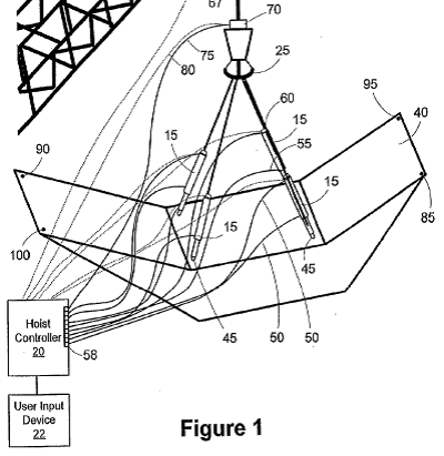
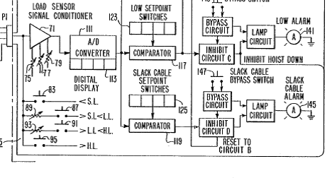
This place covers:
Anti-slack devices using electrical control, e.g. limit switches or tension measurement.
See for example US 4 487 741
This place does not cover:
Anti-slack devices for winches |
This place covers:
Cable or hose arrangements.
See for example US 5 294 066
This place covers:
Energy supply to load engaging elements, including local energy generation devices.
See for example US 5 280 880
This place covers:
Load measurement, either directly or indirectly, e.g. via motor torque.
See for example US 2011/0066394
This place does not cover:
Load measurement on crane hook | |
Load measurement in connection with safety control |
This place covers:
General control arrangements not fitting one of the following subgroups.
See for example US 6 269 635
This place covers:
Hydraulic or mechanical control devices.
See for example US 5 732 835
This place covers:
See for example US 4 614 274
This place does not cover:
Controls for load lifting and lowering | |
Circuits for horizontal motion |
This place covers:
Control of crane lowering and lifting drives.
See for example US 2011/0130863
This place does not cover:
Control drives for winches |
This place covers:
Crane drives with regeneration of energy when lowering.
See for example US 5 936 375
This place covers:
Circuits for horizontal motion control.
See for example US 5 751 126
This place covers:
See for example US4364704
This place covers:
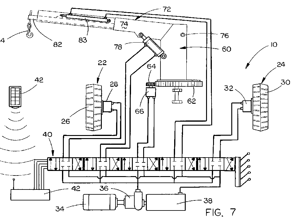
Remote controls for cranes and winches, i.e. outside cabin, includes both hard wired and wireless units.
See for example US 2003/0164349
This place does not cover:
Control devices inside crane cabin |
This place covers:
Control arrangements using hydraulic signal transmission, e.g. between sensor and central unit.
This place covers:
Control arrangements using electric signal transmission, e.g. between sensor and central unit.
See for example US 2009/0250424
This place does not cover:
Remote controls |
This place covers:
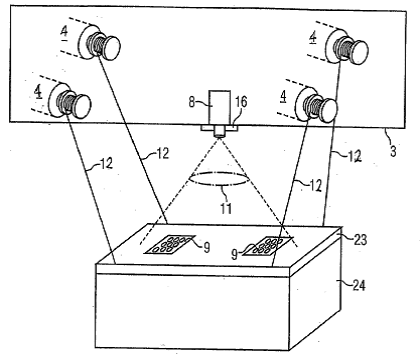
Sensors and cameras for detecting position of loads or parts of crane.
See for example US 2004/0015264
This place covers:
Systems allowing the crane to carry out an automatic movement, for example based on a program or target position, includes path planning and stack optimisation.
See for example US 6 065 619
This place covers:
See for example US 2011/0089131
This place covers:
Engine and motor compartments.
See for example US 4 045 866
This place does not cover:
Operator's compartments |
This place covers:
Operator's compartments.
See for example EP 0 870 725
This place does not cover:
Operating devices | |
Operator's compartments for fork lift trucks | |
Operator's compartments for soil shifting machines |
This place covers:
Control devices actuated by the operator.
See for example US 2007/0156280
This place does not cover:
Remote controls, i.e. outside cabin | |
Controls for fork lift trucks | |
Controls for excavators | |
General control handles |
This place covers:
General crane safety devices not covered by one of the following subgroups
for example component testing.
US 4 643 031
This place does not cover:
Safety devices for boom cranes | |
Safety devices for winches |
This place covers:
See for example US 5 735 507
This place covers:
See for example DE 10 2009 006 103
This place covers:
Electrical anti-collision devices.
See for example US 3 167 753
This place covers:
Non-electric devices, e.g. with visual indication
See for example US 2007/0205618
This place covers:
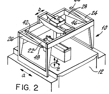
Devices where the load carrying element is connected to the lifting beam, i.e. not suspended by cables.
See for example EP 0 314 632
This place covers:
Specially adapted devices, i.e. with particular mechanical features making them especially suitable for a particular application not covered by the following subgroups.
This place covers:
See for example EP 2 275 764
This place covers:
See for example US 4 736 971
This place covers:
See for example DE 1 181 866 B
This place covers:
See for example DE 1 109 196 B
This place covers:
See for example DE 35 08 195
This place covers:
See for example US 5 803 280
This place does not cover:
Gantry cranes or straddle carriers |
This place covers:
See for example US 1 497 961
This place covers:
See for example US 2011/0142590
This place covers:
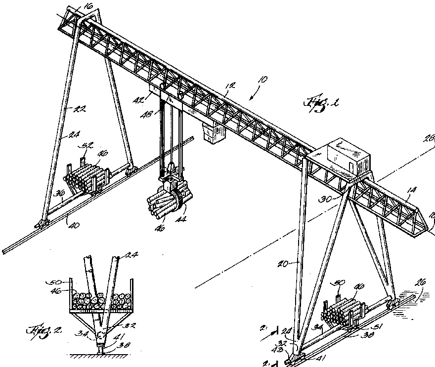
Gantry cranes not covered by the following subgroups.
See for example US 5 405 029
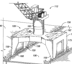
This place covers:
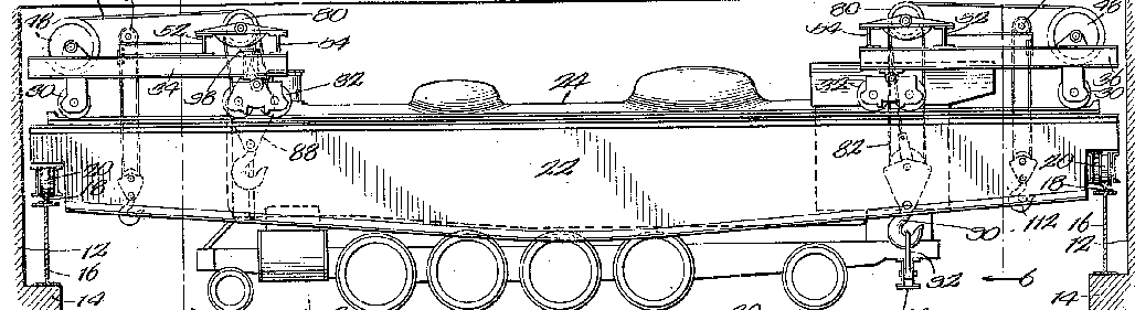
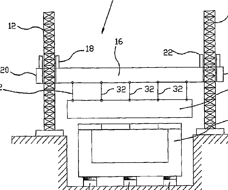
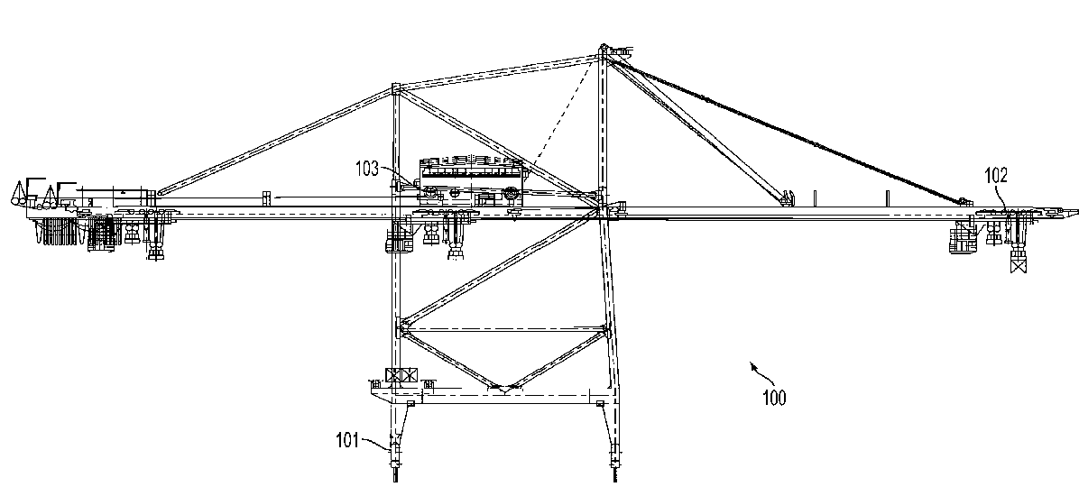
Gantry cranes for containers, i.e. static cranes or cranes with wheels which are static when handling loads.
See for example US 2009/0191028
This place does not cover:
Straddle carriers for containers |
This place covers:
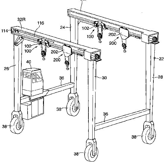
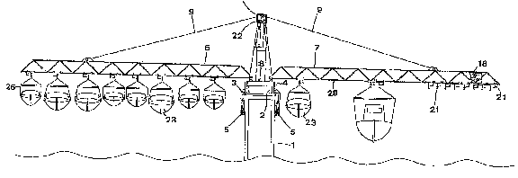
Straddle carriers for loads other than containers, e.g. boats.
See for example US 5 893 471
This place does not cover:
Straddle carriers for containers |
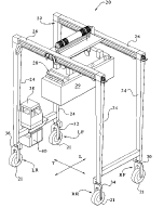
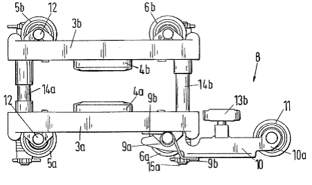
This place covers:
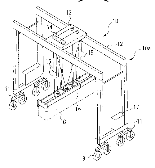
Straddle carriers for containers, i.e. wheeled devices which carry containers around ports.
See for example EP 1 829 810
This place does not cover:
Gantry cranes for containers |
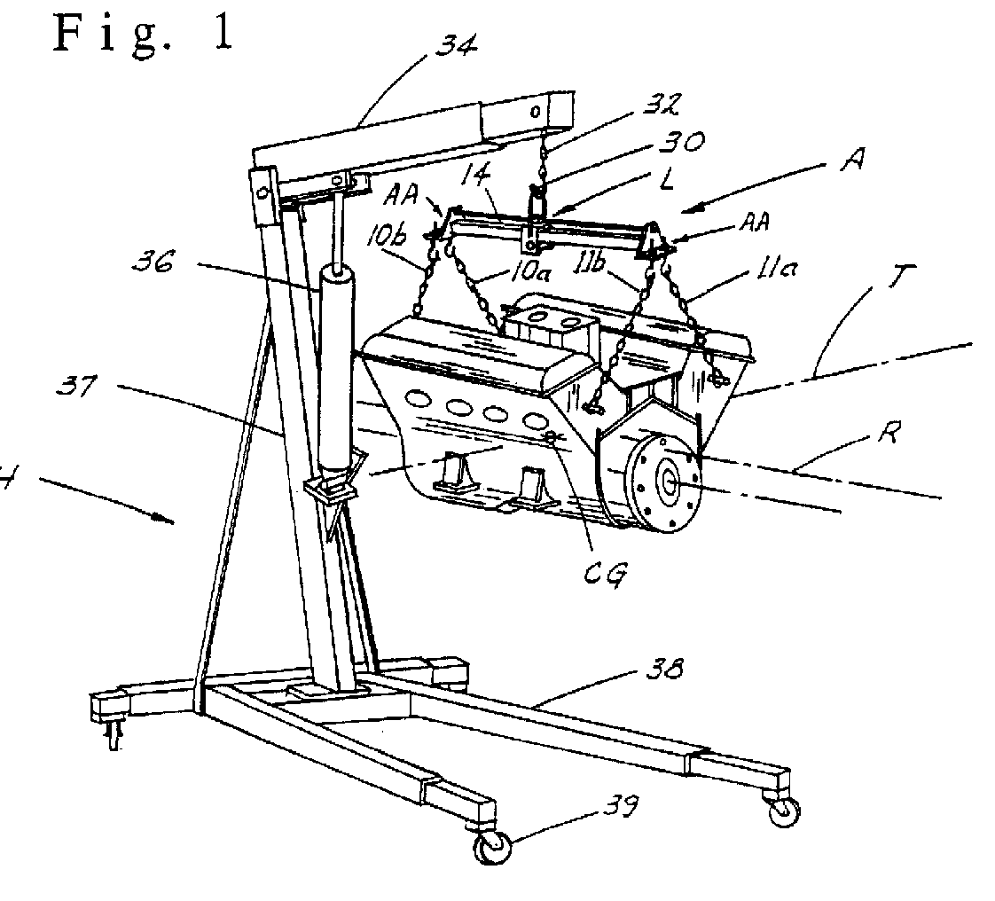
This place covers:
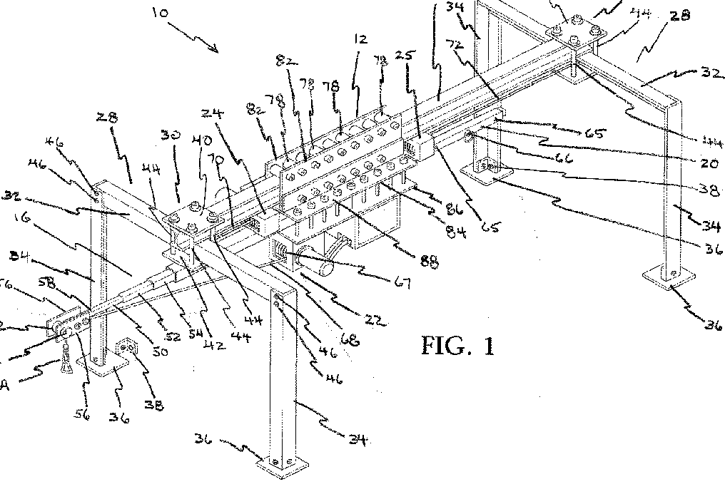
Easily dismantlable gantry cranes.
See for example US2007/0163982
This place covers:
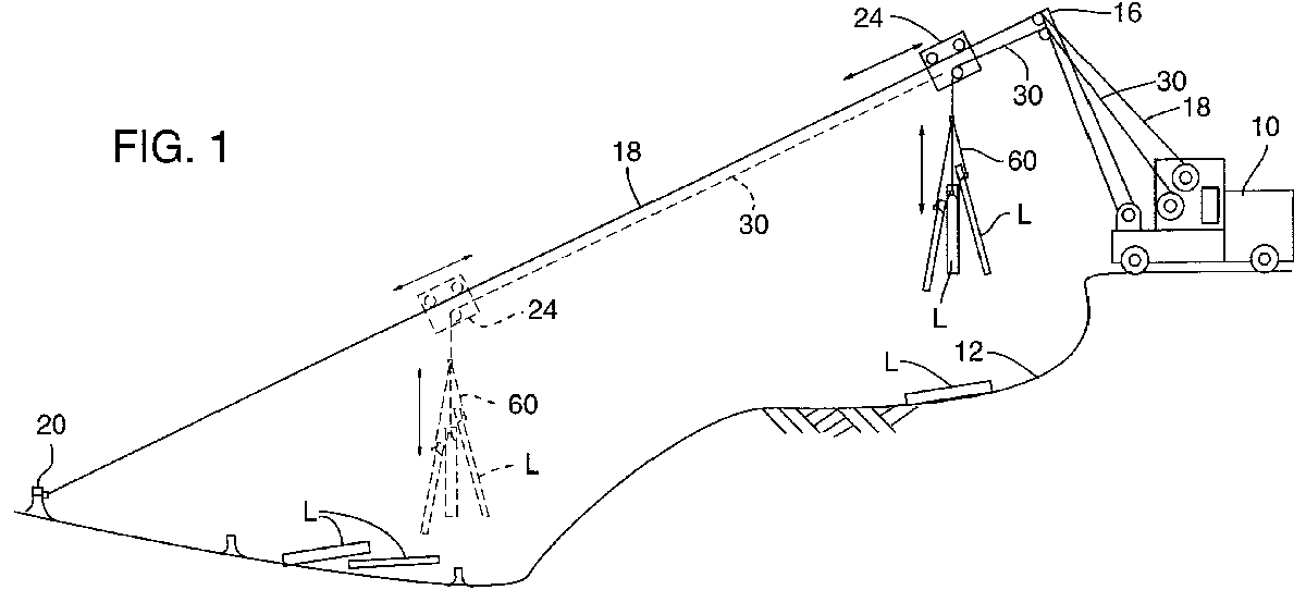
Devices not falling into one of the following subgroups.
See for example US 7 234 605
This place covers:
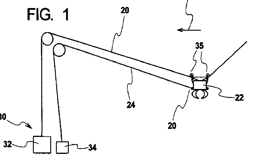
Cable cranes where one support for the end of the cable is pivotable.
See for example GB 130 008
This place covers:
Cable cranes where one end of the cable is not fixed.
See for example US 5 816 636
This place covers:
See for example DE 30 37 894
This place covers:
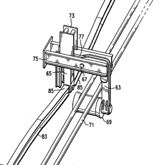
Arrangements for supporting cables.
See for example US 4 355 727
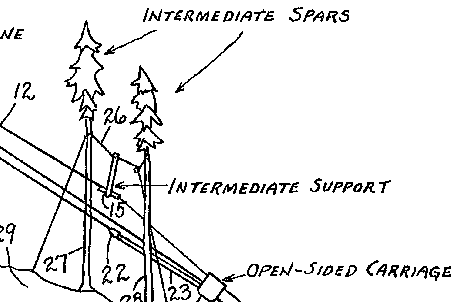
This place covers:
Supports which are movable along the cable.
See for example GB 374 921
Stationary cranes are classified in B66C 23/00 - B66C 23/24.
Tower type cranes (which may be mobile) are classified in B66C 23/26 - B66C 23/34.
Mobile cranes are classified in B66C 23/36 and later subgroups.
Groups B66C 23/54 onwards apply to all types of crane.
This place covers:
See for example US 5 203 837

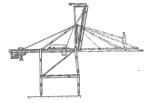
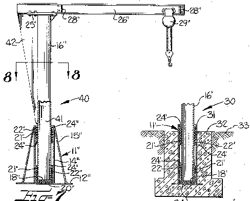
This place covers:
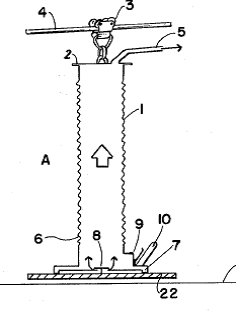
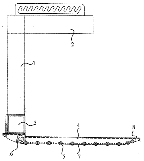
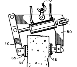
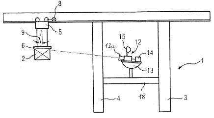
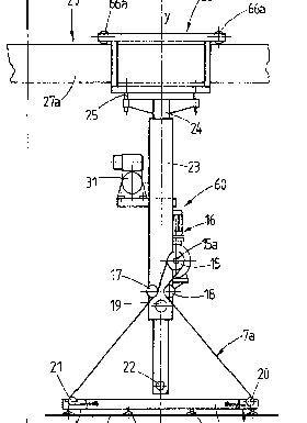
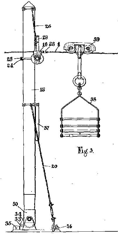
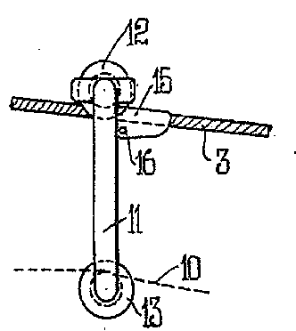
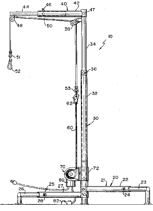
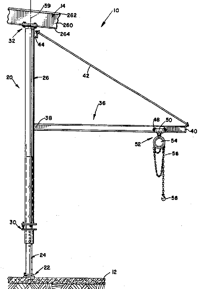
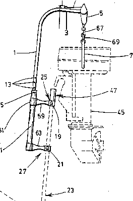
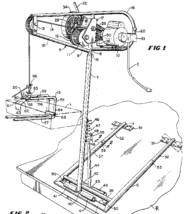
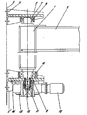
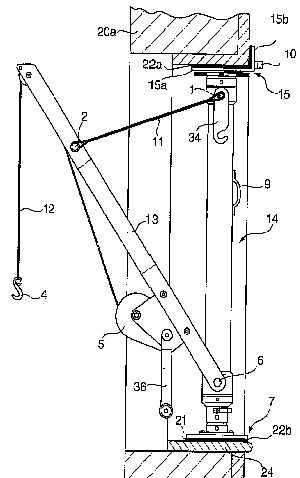
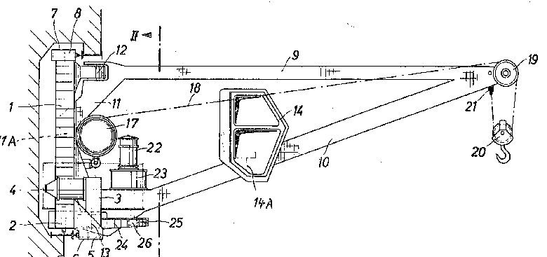
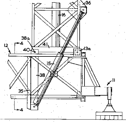
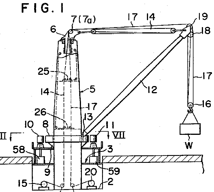
Jib cranes with a fixed vertical column mounted on the ground as the sole support, with a jib mounted for slewing at the top of the column, i.e. the column does not rotate and the inclination of the jib can not be altered.
This place does not cover:
Jib cranes where the column also rotates or the jib inclination can be altered | |
Jib cranes which are supported by other means, e.g. additional support from a building | |
Mobile cranes | |
Vehicle mounted cranes | |
Small cranes on wheels |
This group is only used if the following subgroups are not applicable. Documents may be classified in more than one subgroup.
This place covers:
Jibs pivoting around the centre of the column.
See for example WO 2009/003554
This place covers:
See for example EP 1 460 024
This place covers:
Jibs whose pivot is not in line with the axis of the column.
See for example US 6 367 855
This place covers:
See for example US 5 509 638
This place does not cover:
Telescopic booms e.g. for mobile cranes |
This place covers:
Fixed cranes with luffing jibs not covered by one of the subgroups B66C 23/08 - B66C 23/14.
This place does not cover:
Column mounted luffing jibs | |
Derricks | |
Luffing mechanisms |
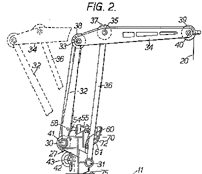
This place covers:
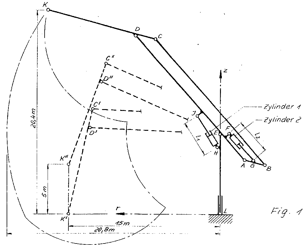
Mechanical arrangements for following a particular non-horizontal path.
See for example DE 44 15 029
This place does not cover:
Control devices for particular paths |
This place covers:
See for example US 3 884 359
This place covers:
See for example GB 1 392 223
This place covers:
See for example GB 985 801
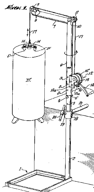
This place covers:
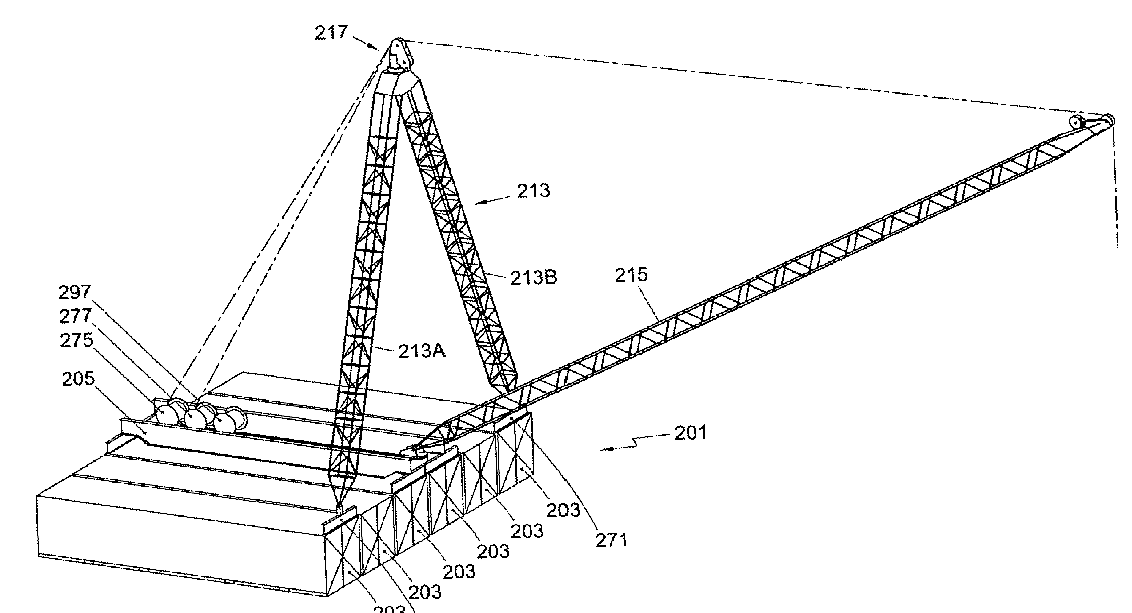
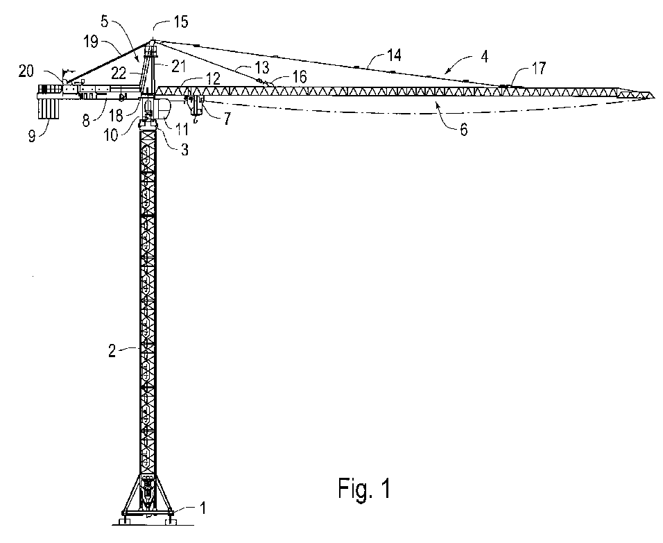
Jib cranes with a fixed vertical column mounted on the ground as the sole support, includes cranes with a jib mounted for slewing at the centre or bottom of the column, i.e. at least part of the column rotates. the jib may or may not be inclinable.
See for example US 3 358 849
This place does not cover:
Jib cranes with a jib mounted for slewing at the top of the column, i.e. the column does not rotate and the inclination of the jib can not be altered. | |
Jib cranes which are supported by other means, e.g. additional support from a building | |
Vehicle mounted cranes | |
Small cranes on wheels | |
Derrick cranes |
This place covers:
See for example US 3 181 707
This place does not cover:
Cranes where all the column is fixed |
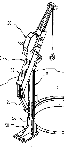
This place covers:
Small cranes without wheels.
See for example US 2005/0161422
This place covers:
Cranes with jibs for specific applications not covered by the following groups B66C 23/20 - B66C 23/52.
See for example US 2001/0051074
This place covers:
See for example US 2005/0211653
This place does not cover:
Load connecting element for lifting wind turbines | |
Cranes supported on or by wind turbines |
This place covers:
Jib cranes which are not supported only by a simple foot on the ground, but (also) by other means, e.g. additional support from a building, which do not fit one of the following subgroups.
This place does not cover:
Vehicle mounted cranes | |
Small cranes on wheels |
This place covers:
Supported either from only above or from both above and below.
See for example US 4 096 952
This place does not cover:
Cranes supported in window openings |
This place covers:
Cranes supported only from below, but requiring extra support, i.e. not merely mounted by a simple crane foot.
See for example US 2 382 299
This place does not cover:
Cranes supported both from below and above |
This place covers:
See for example US 4 880 345
This place does not cover:
Cranes attached to wind turbines |
This place covers:
See for example US 3 671 015
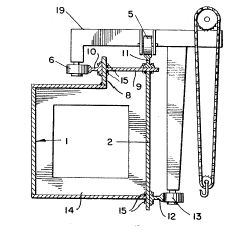
This place covers:
Cranes mounted on or in containers
See for example EP 2 196 427
This place covers:
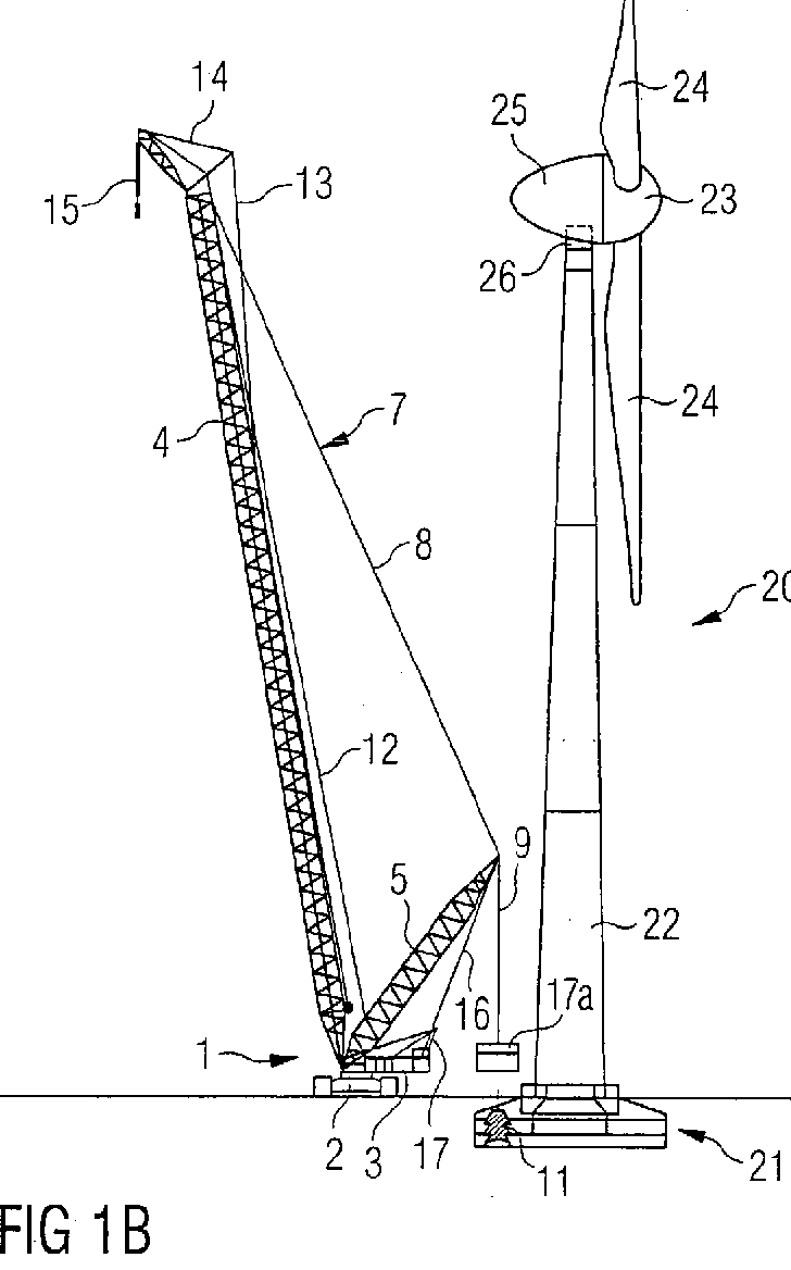
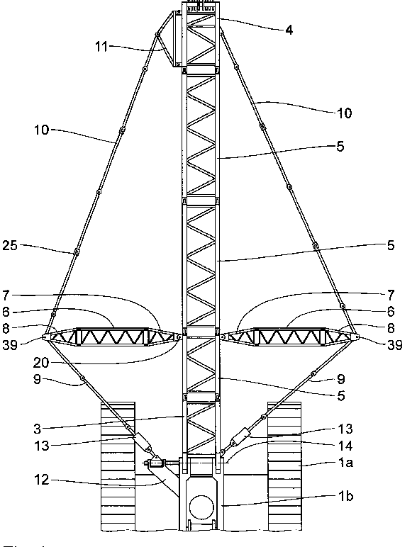
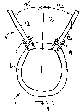
Mounted on or supported by wind turbines or for erecting wind turbines.
See for example EP1 677 007
This place does not cover:
Load connecting element for lifting wind turbines | |
Cranes not supported by the wind turbine |
This place covers:
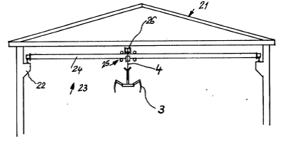
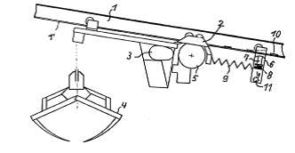
Cranes fixed to walls, i.e. which do not move relative to the wall.
See for example GB 2 037 701
This place does not cover:
Cranes which can run along walls |
This place covers:
See for example US 2008/0035594
This place covers:
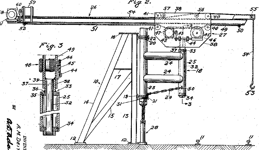
Cranes with a jib which runs along a wall.
See for example US 3 050 195
This place does not cover:
Cranes fixed to walls, i.e. which do not move relative to the wall |
This place covers:
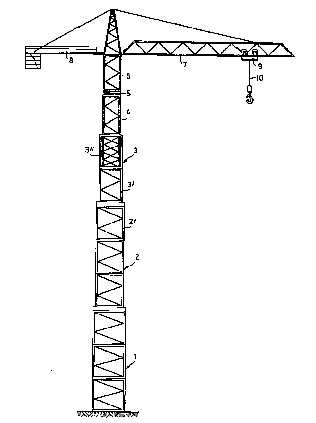
Tower type cranes not fitting one of the subgroups B66C 23/28 - B66C 23/34.
See for example US 6 422 408
This place covers:
Tower cranes where the jib does not have a fixed tower height relative to the ground and do not fit the following two subgroups.
This place does not cover:
Cranes where the tower is telescopic | |
Cranes which climb |
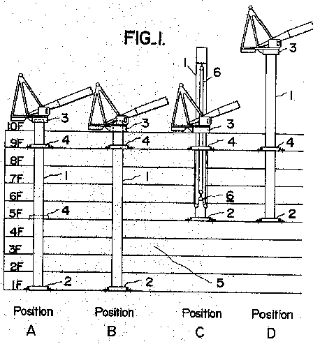
This place covers:
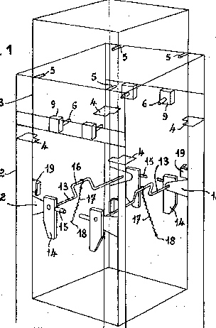
Cranes which have towers which can be extended by adding an extra section to the tower.
See for example US 4 028 792
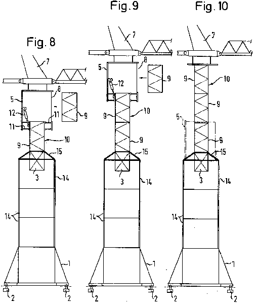
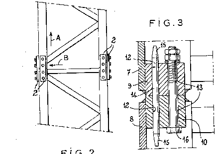
This place covers:
Cranes which have towers which can be extended by a telescoping section of the tower.
See for example US 4 196 814
This place covers:
Cranes which can alter the height of the jib and top of tower by climbing up other structures.
See for example US 3 485 384
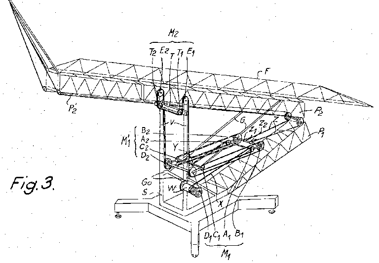
This place covers:
Cranes which can assemble or erect themselves into their working configuration, not falling into one of the following four subgroups.
See for example US 3 378 147
This place does not cover:
Mobile cranes with arrangements for assembling and lifting the boom from the ground. |
This place covers:
Cranes which erect by extending a telescopic section.
See for example US 4 446 975
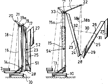
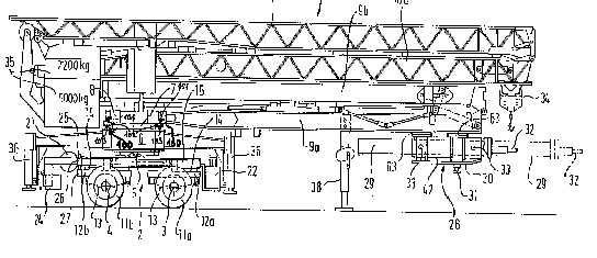
This place covers:
Where the arrangement relates specifically to transport of the crane, i.e. not merely to folding the tower and jib to the horizontal position.
See for example US 2004/0221673
This place does not cover:
Mobile cranes dismantlable for transport |
This place covers:
Cranes with devices for locking the elements into their operating or transport positions.
See for example US 3 856 150
This place covers:
Cranes where the erecting mechanism uses jacks instead of for example winches and cables.
See for example US 2003/0127409
This place covers:
Vehicle mounted cranes not fitting one of the subgroups B66C 23/38 – B66C 23/545.
This place covers:
See for example US 2007/0221600
This place does not cover:
Tower cranes dismantlable for transport |
This place covers:
Mobile cranes with more than one engine, e.g. where the engine driving the crane lifting functions is not used for propelling the crane along a road.
This place covers:
Where the same engine is used for driving the lifting functions and wheels or tracks.
This place covers:
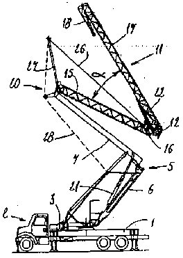
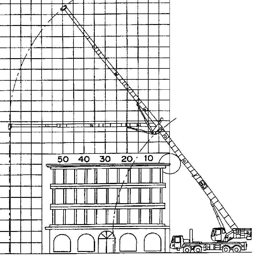
Mobile cranes with telescopic or extendable jibs, or jibs which change configuration during operation.
See for example US 5 704 498
This place does not cover:
Cranes with jibs which are folded for transport using cylinders. |
This place covers:
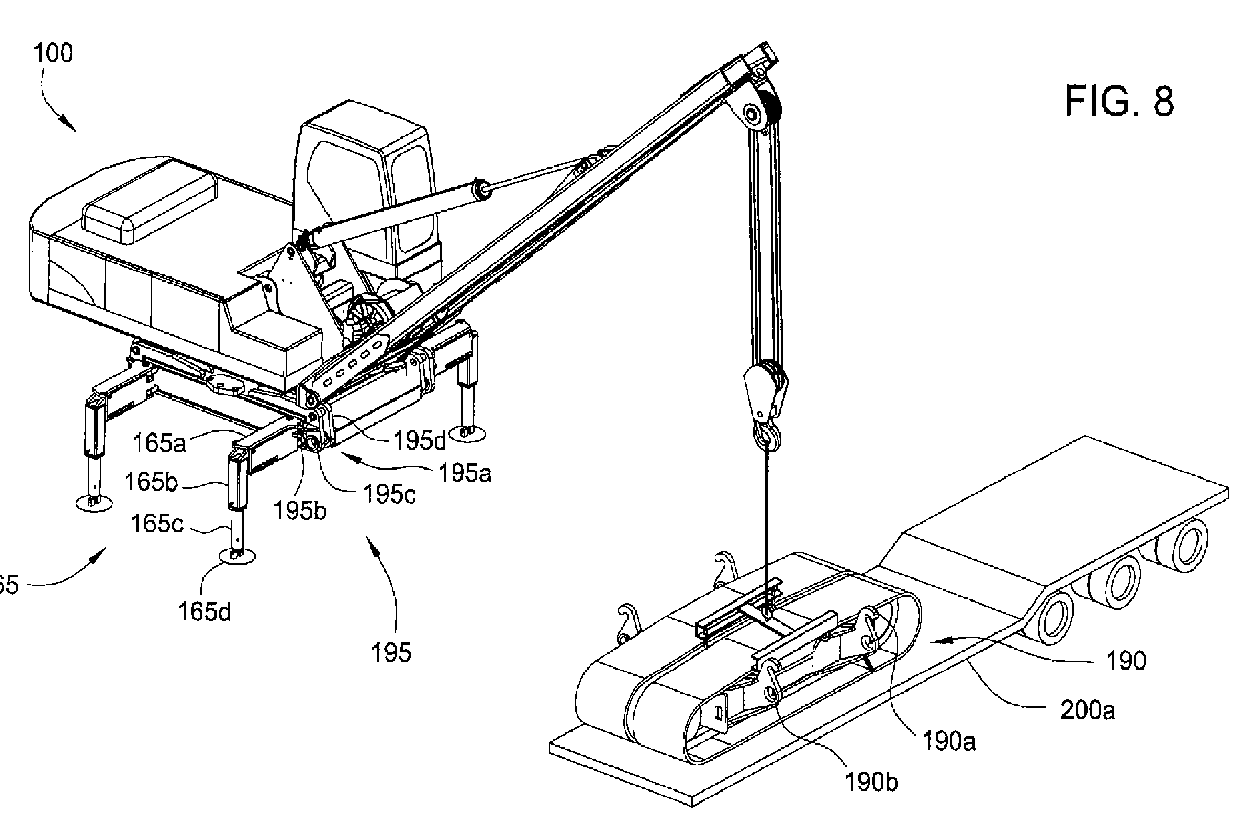
Vehicle mounted cranes, i.e. mounted on a normal vehicle rather than a mobile crane where the chassis is specially constructed for a crane.
pipe laying cranes where a boom is mounted to one side of a wheeled or tracked chassis.
See for example US 6 138 991 or US 7 600 646
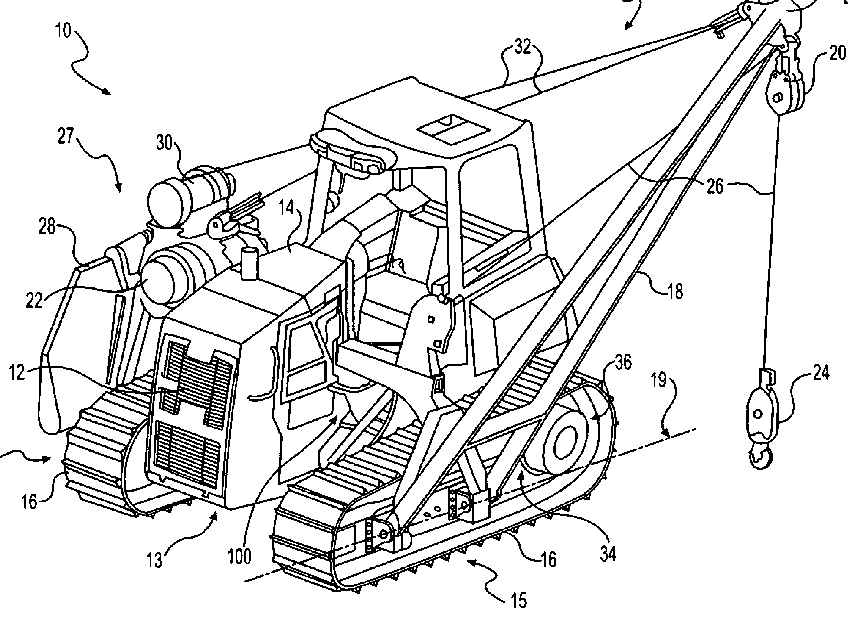
This place does not cover:
Cylinder operated jibs on trucks |
This place does not cover:
Pipe laying cranes |
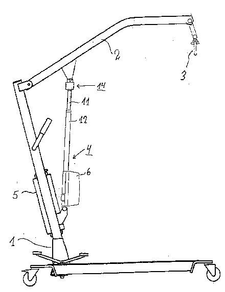
This place covers:
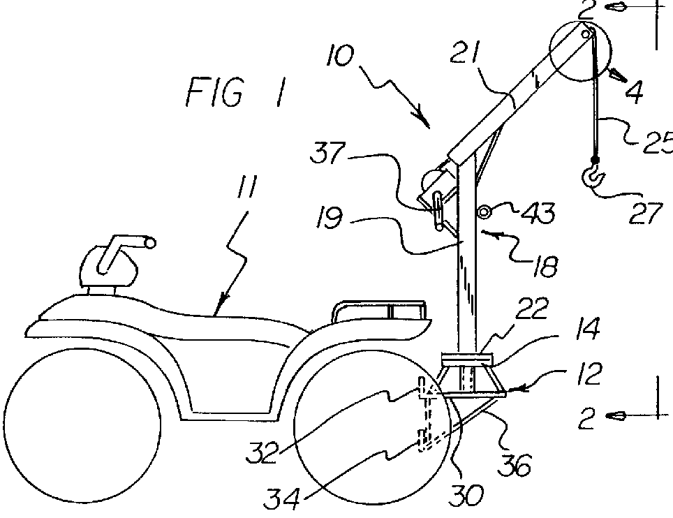
Small cranes on wheels which can be moved around manually or have simple drives.
See for example US 2011/0043062
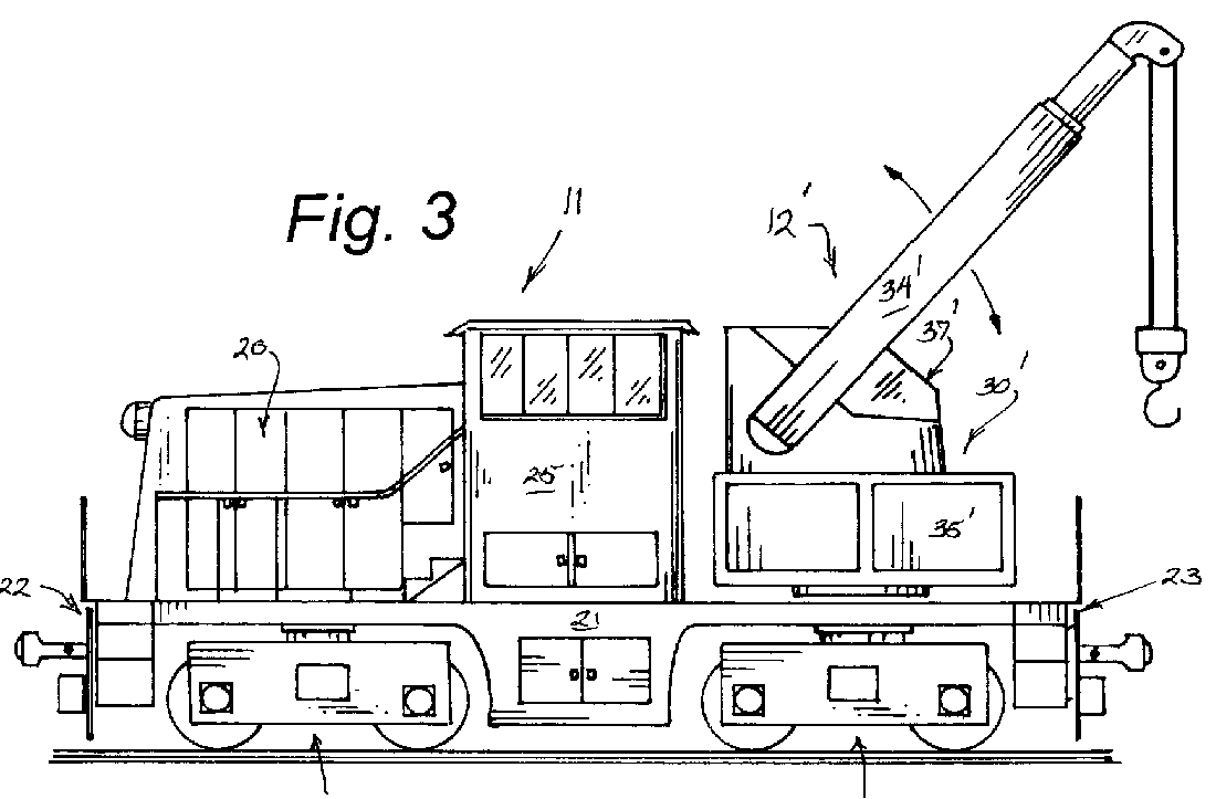
This place covers:
See for example US 5 800 000
This place does not cover:
Load connecting element for lifting engines |
This place covers:
See for example US 6 691 881
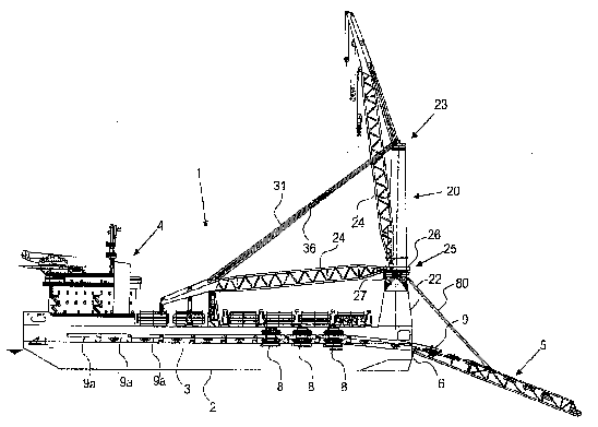
This place covers:
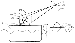
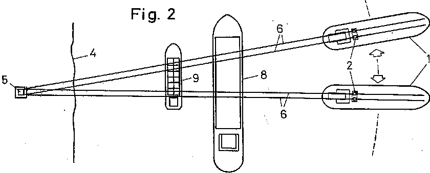
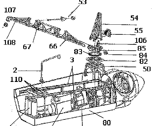
Cranes mounted on a ship or other floating structure.
See for example US2011/0031205
This place covers:
Cranes with double jibs.
See for example US 3 684 104
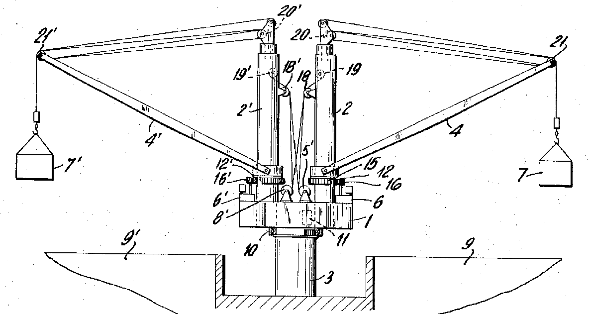
This place does not cover:
Cranes with double jibs mounted on land |
This place covers:
See for example WO2011/019121
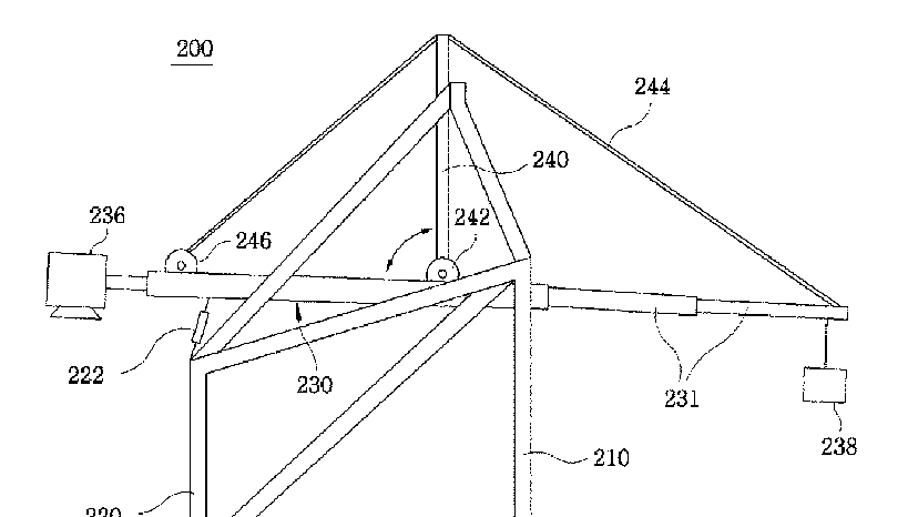
This place covers:
Jib cranes with hydraulic cylinders, e.g. for folding jib for transport.
See for example EP 1 707 529
No corresponding IPC exists. Subject matter should be given an IPC classification in B66C 23/68
This place covers:
See for example EP 0 733 585
This place covers:
See for example US 4 091 943
This place covers:
See for example US 4 187 949
This place does not cover:
Double derricks on ships |
This place covers:
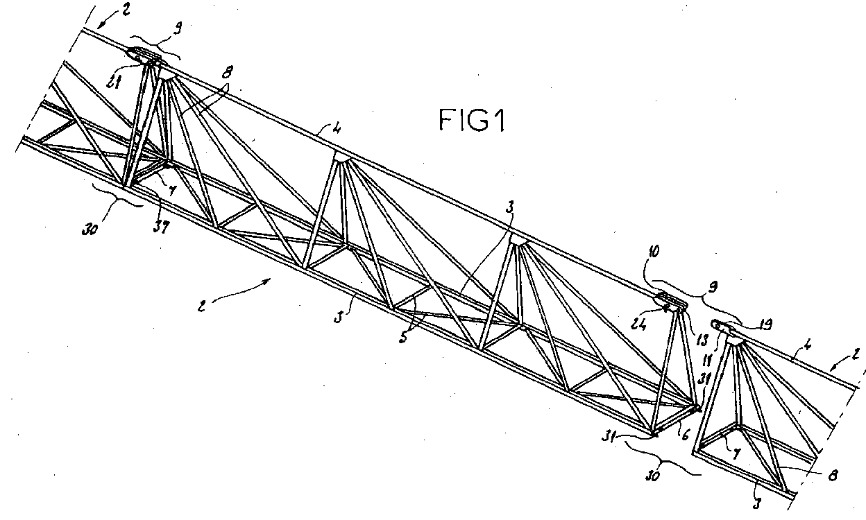
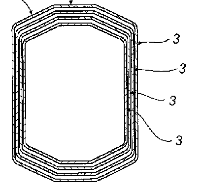
Construction of jibs not covered by the following subgroups, e.g. non-telescopic jibs.
See for example US 2011/0114587
This place does not cover:
Telescopic jibs |
This place covers:
See for example EP 1 156 007
This place does not cover:
Jib extensions for telescopic jibs |
This place covers:
See for example US 2010/0294738
This place does not cover:
Folding jibs using cylinders | |
Extendable jibs | |
Telescopic jibs |
This place covers:
See for example US 2004/0238471
This place does not cover:
Telescopic jibs |
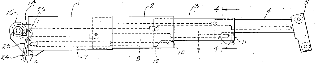
This place covers:
Telescopic sections.
See for example EP 1 302 435
Telescoping actuator arrangements with a combination of actuators, e.g. by both cables and cylinders.
See for example US3721054
This place covers:
See for example US 2005/0098524
This place covers:
See for example US 3 638 806
This place does not cover:
Telescoping arrangements using both cables and cylinders |
This place covers:
See for example US 5 678 708
This place does not cover:
Telescoping arrangements using both cables and cylinders |
This place covers:
See for example US 4 298 128
This place covers:
Bearings between telescopic sections.
See for example US 6 499 612
This place covers:
Arrangements to lock the telescopic sections in a particular position.
See for example US 6 216 895
This place covers:
Counterweights associated with jib.
See for example US 6 494 330
This place does not cover:
Counterweights separate from jib |
Attention is drawn to the following places, which may be of interest for search:
Counterweights for excavators |
This place covers:
Static counterweights not associated with jib.
See for example US 2006/0043042
This place does not cover:
Movable counterweights not associated with jib |
This place covers:
Movable counterweights not associated with jib.
See for example US 6 568 547
This place covers:
See for example US 2010/0102018
This place does not cover:
Hydraulic outriggers |
Attention is drawn to the following places, which may be of interest for search:
Outriggers for excavators |
This place covers:
See for example US 2004/0197181
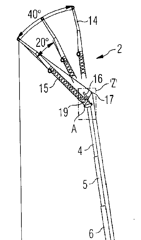
This place covers:
Devices for luffing the jib, including for erection purposes.
See for example US 2005/0098522
This place does not cover:
Self erecting cranes, e.g. tower cranes |
This place covers:
Bracing equipment to support bending load on the jib or boom, not covered by one of the following subgroups.
This place covers:
See for example EP 1 213 254
This place covers:
See for example EP 2 271 576
This place covers:
See for example US 2004/0129663
This place covers:
See for example US 2002/0070187
This place covers:
Devices for slewing the upper works or boom of a crane.
See for example US2009/0074552
This place does not cover:
Hydraulic slewing devices |
This place covers:
Devices for slewing the upper works or boom of a crane using hydraulic motors or cylinders.
See for example US 7 677 861
This place covers:
Safety gear for boom cranes not covered by one of the subgroups B66C 23/90 - B66C 23/94.
This place does not cover:
General crane safety devices |
This place covers:
Non-electrical safety devices.
This place covers:
See for example US 2 840 244
This place covers:
See for example US 2007/0144995