CPC Definition - Subclass B23F
This place covers:
Methods and machines specially designed to accurately produce the shapes of gears and other toothed members. Such shapes being essential for proper intermeshing of gearing (and toothed member) elements to ensure the required relative motions. The methods and machines use metal removing processes;
Tools which are specially adapted for use in machines for manufacturing toothed members;
Accessories and equipment for gear making machinery.
This place does not cover:
Attention is drawn to the following places, which may be of interest for search:
Details, components, or accessories for machine tools, in general | |
Machines or devices for grinding or polishing, per se | |
Gears, per se | |
Profiles of toothed members |
In this place, the following terms or expressions are used with the meaning indicated:
Terms relating to gear nomenclature in general are to be understood as defined by ANSI/AGMA 1012-G05
Gear teeth | In addition to the common meaning of gear teeth, it also covers the teeth or lobes of other accurately intermeshing members having relative movement of a similar kind, such as rotors of rotary pumps and blowers. |
Gear cutting | Whilst "cutting" is generally used to refer to material removal using a geometrically defined cutting edge, in this subclass the term "gear cutting" also refers to material removal using geometrically undefined cutting edges, such as by grinding. |
Profile | Profile may include the outline of both faces or only one face of a tooth, or the opposing faces of adjacent teeth. |
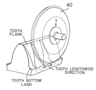
Straight | Straight means that a tooth as a whole (ignoring any curvature of the tooth-face alone, e.g. crowning) is straight in the direction of its length. It accordingly includes the teeth of spur gears, helical gears and normal bevel gears. |
Indexing | Indexing in general refers to the process of dividing the periphery of the workpiece into a number of discrete sections. In this subclass the sections are where the teeth are (or will be) formed and indexing refers to the relative angular movement between the workpiece and tool after cutting one tooth in order to allow cutting of the next tooth. |
Continuous indexing | Continuous indexing refers to using continuous rotation of the workpiece to enable all teeth to be cut without separation of tool and workpiece for indexing. |
Generating | Generating refers to the method of cutting gear teeth using a cutting tool having (or through machine movement, simulating) the shape of a particular gear or rack (dependent on type of gear being produced) and moving the tool relatively to the work piece with a rolling-off motion to cut the tooth profile. |
Grinding | Grinding refers to material removal using tools with fixed abrasive particles having geometrically undefined cutting edges. |
Planing or Slotting | Planing or slotting refers generally to the removal of material in the form of chips by a relative movement of at least one tool with a geometrically defined cutting edge and the workpiece, along a non-circular trajectory, both tool and workpiece being non-rotating. However in this subclass there may be a relative rotational movement in order to generate tooth profiles. |
Skiving | Skiving refers to the removal of material in the form of chips from the workpiece by a toothed tool having geometrically defined cutting edges. The tool and workpiece are both rotated with their rotation axes being at a skewed angle. The tool is fed generally parallel to the workpiece axis. |
Milling | Milling refers to the removal of material in the form of chips from a workpiece using a rotating tool with a geometrically defined cutting edge where the main cutting force results from the rotation of the tool. |
Hobbing | Hobbing is a milling process where the tool takes the form of a worm in which the threads are gashed to form cutting edges. Both tool and workpiece are rotated. It is a continuous generating process. |
Face Milling | Face milling is a milling process where the cutting edges of the tool are on teeth or cutter bars which extend axially from a face of the (usually) circular tool, the face being transverse to the tool rotation axis. |
Face Hobbing | Face hobbing is a face milling process using continuous indexing. |
Broaching | Broaching refers to the removal of material in the form of chips from a workpiece by a relative movement between a tool having multiple teeth and a workpiece along a non-circular trajectory. The difference in height between successive teeth on a broaching tool determines the feed and hence the chip thickness. |
Broach-milling | Broach-milling refers to milling with a rotary cutter having a number of teeth of progressively increasing depth or width |
Pot broaching | Pot broaching refers to broaching external teeth with an internally toothed tool. |
Honing | Honing generally refers to abrading by means of one or more, often compliant, fine grit abrasive tools along a controlled path of combined movements, including a reciprocating movement, in order to smoothen a surface. In this subclass honing also refers to a surface finishing method using toothed tools where tool and workpiece are in crossed axis meshed engagement. |
Lapping | Lapping refers to a surface finishing method using abrasives dispersed in a liquid medium or paste on the engaging surfaces of a workpiece, usually whilst the workpiece is in meshed engagement with another toothed member. |
Shaving | Shaving refers to a surface finishing method of material removal in the form of chips using a toothed tool with gashes in the flanks of the teeth that act as the geometrically defined cutting edges, the tool and workpiece are in crossed axis meshed engagement. |
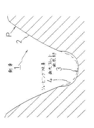
This place covers:
Methods and machines for making gear teeth using a tool which matches the required tooth profile.
Examples are:
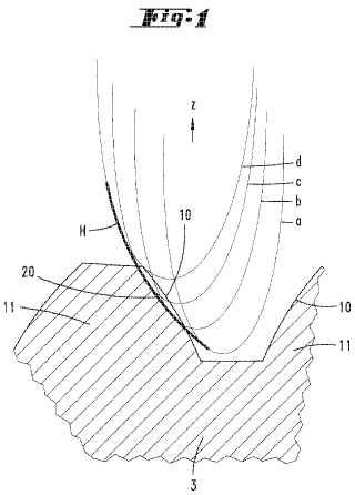
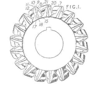
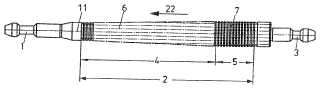
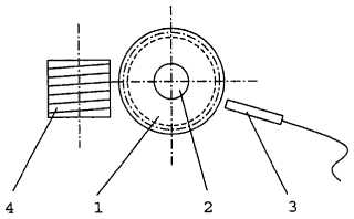
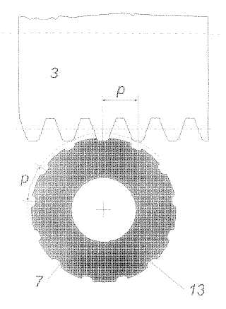
Manufacturing by grinding (JP59161226):
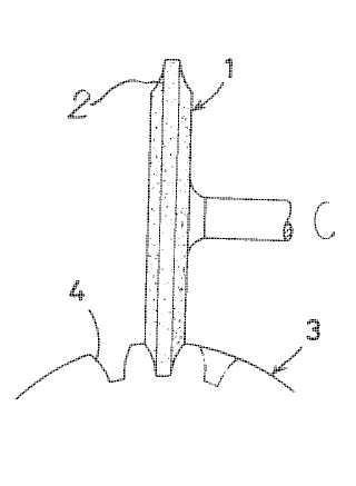
tool (1), workpiece (3)
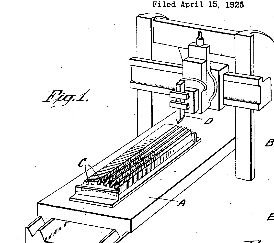
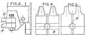
Manufacturing by planing or slotting (US1636670)
tool (D); workpiece (C)
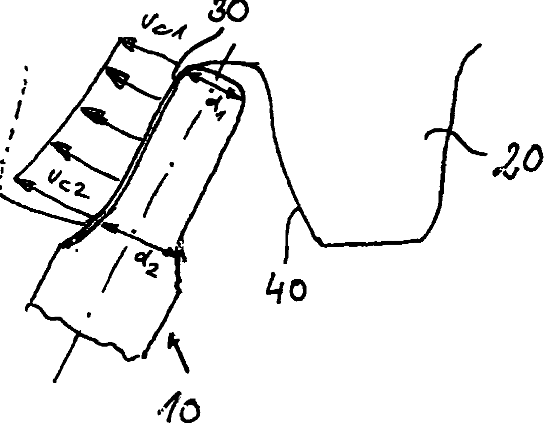
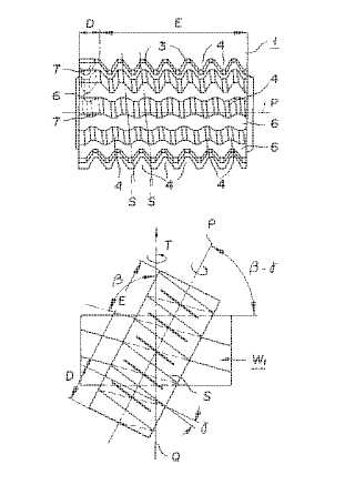
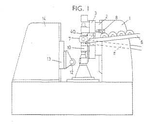
Manufacturing by milling (US2013101367
tool (10), workpiece (20)
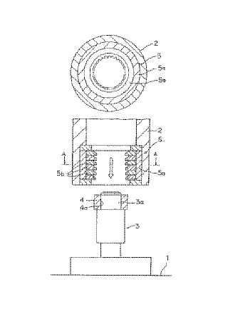
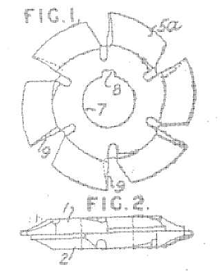
Manufacturing by broaching (JP4025313)
tool (5), workpiece (4)
This place does not cover:
Gear cutting tools |
Attention is drawn to the following places, which may be of interest for search:
Where a machine is also used for generating gear straight gear teeth it is additionally classified in the subgroups of B23F 5/00.
Attention is drawn to the following places, which may be of interest for search:
Gear generating by grinding | |
Chamfering gear teeth by grinding | |
Grinding, in general |
Attention is drawn to the following places, which may be of interest for search:
Gear generating using a grinding worm |
This place covers:
Planing or slotting refers to the removal of material in the form of chips by a relative movement of at least one tool with a geometrically defined cutting edge and the workpiece, along a non-circular trajectory. The tool and workpiece are generally non-rotating. There may be a rotary indexing movement in between cutting passes
Attention is drawn to the following places, which may be of interest for search:
Gear generating by planing or slotting |
This place covers:
Milling refers to the removal of material in the form of chips from a workpiece using a rotating tool with a geometrically defined cutting edge where the main cutting force results from the rotation of the tool.
This place covers:
Machines and methods for making gear teeth using templates which have a profile matching at least a part of the required tooth profile. This class includes roughing and finishing, including chamfering teeth.
Example: DE763595 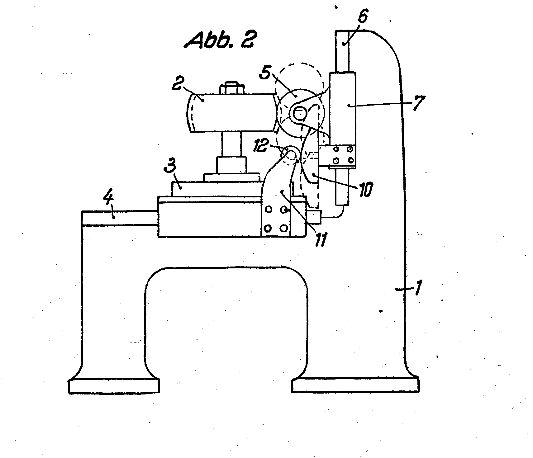
Attention is drawn to the following places, which may be of interest for search:
Copying systems or devices per se |
This place covers:
Machines and methods of making straight gear teeth involving moving the tool relatively to work piece with a rolling-off motion, e.g. generating. The methods include but are not limited to:
- grinding, with a grinding worm or grinding disc
- planing, including shaping and skiving
- milling, including hobbing
Example(s):
By grinding (US4400916)
by planing or slotting (EP1342524)
tool (44), workpiece (12)
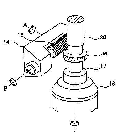
by hobbing (JP2010158748)
tool (15), workpiece (W)
Attention is drawn to the following places, which may be of interest for search:
Making curved gear teeth |
Attention is drawn to the following places, which may be of interest for search:
This place covers:
Skiving refers to the removal of material in the form of chips from the workpiece by a toothed tool having geometrically defined cutting edges. The tool and workpiece are both rotated with their rotation axes being at a skewed angle. The tool is fed generally parallel to the workpiece axis, depending on the type of gear being cut
Example (DE102007015357)
tool (3), workpiece (14)
In patent documents, the following words/expressions are often used as synonyms:
- "Skiving" and "hob peeling"
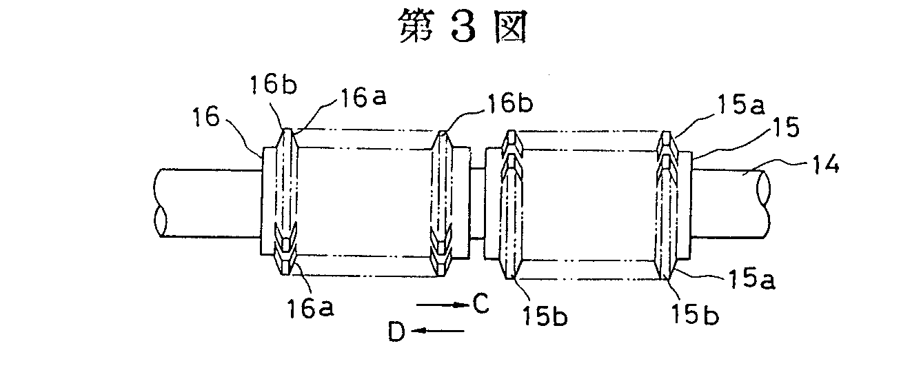
This place covers:
Example (JP359182020)
plural hobs, 15,16
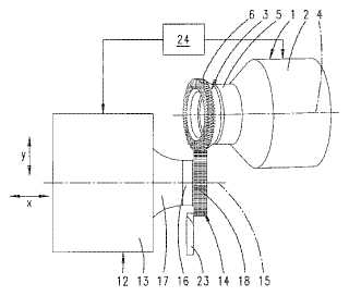
This place covers:
Example (DE1269869)
tools (5), workpiece (10)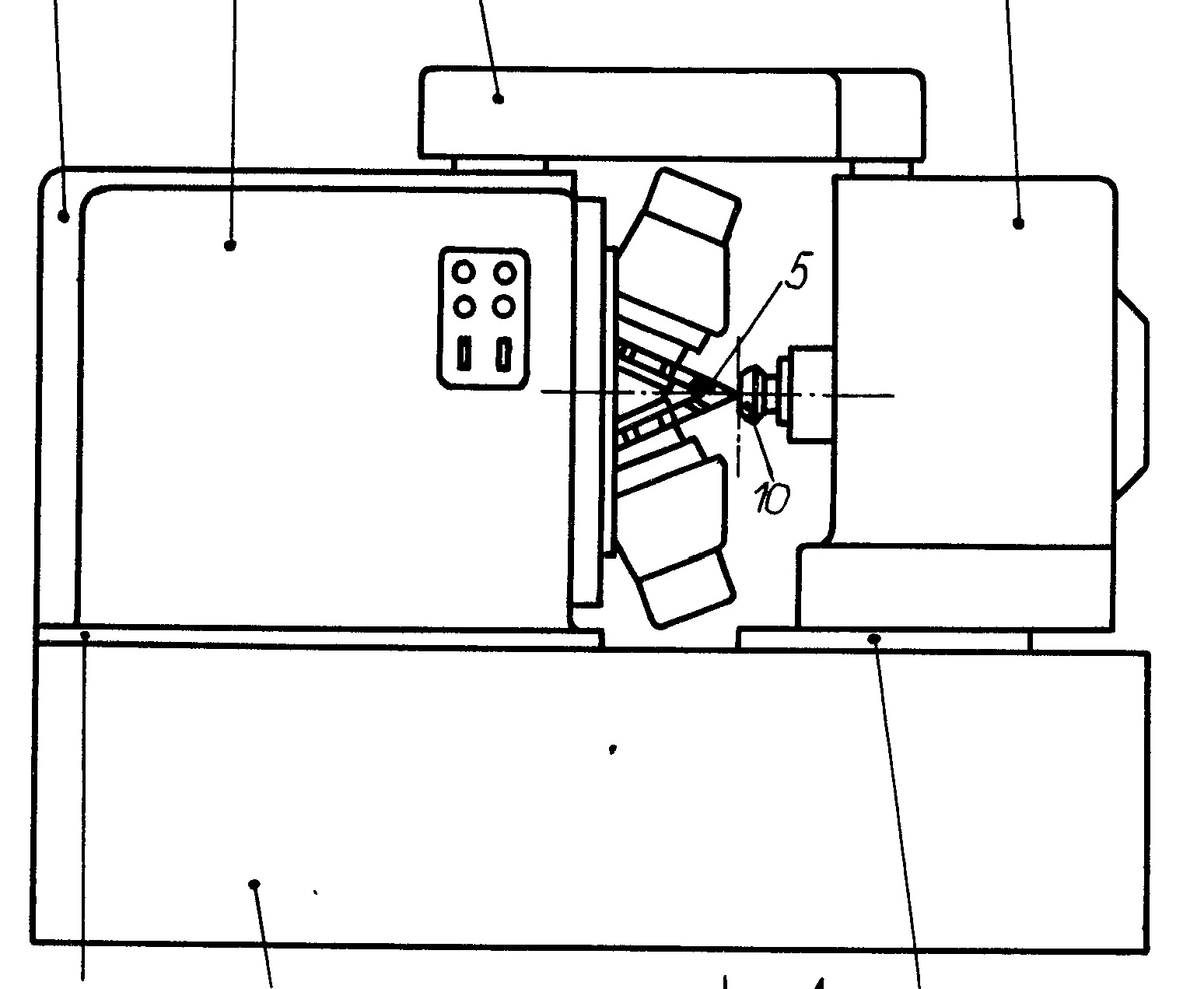
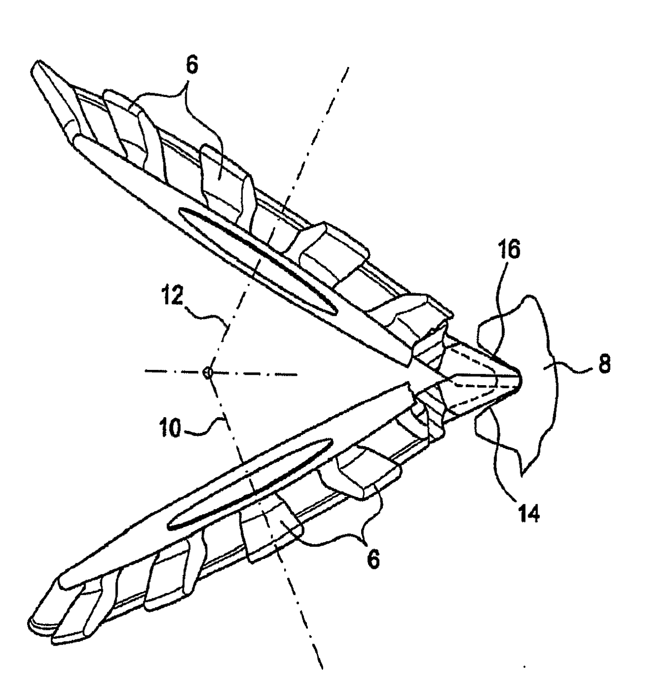
Example (US7364391)
tools (6), workpiece (8)
Attention is drawn to the following places, which may be of interest for search:
Gear manufacturing hobs, per se |
Attention is drawn to the following places, which may be of interest for search:
Taper hobs for manufacturing bevel gears |
This place covers:
Methods and machines for making herringbone and double helical gears.
Example (US20040031152):
This place covers:
Methods and machines for making gears having teeth curved in their longitudinal direction, i.e. the tooth is curved along the tooth direction. e.g. spiral bevel gears, hypoid gears.
Example (US20050064794)
tool 7, Workpiece 31
(US20020154961)
tool 18, workpiece 50
Attention is drawn to the following places, which may be of interest for search:
Face-mill-type grinding tools |
Methods and machines relating to both face-mill-type grinding and face milling using milling cutters are also to be classified in B23F 9/10.
Attention is drawn to the following places, which may be of interest for search:
Gear shaper cutters having a shape similar to a spur gear or part thereof |
This place does not cover:
Face hobbing |
Attention is drawn to the following places, which may be of interest for search:
Hobs for gear cutting |
Attention is drawn to the following places, which may be of interest for search:
Tapered hobs |
Attention is drawn to the following places, which may be of interest for search:
Face mills for gear cutting |
Methods or machines relating to both face-mill-type grinding and face milling using a milling tool are also to be classified in B23F 9/025.
This place covers:
Methods and machines for manufacturing curved gear teeth by milling with a face mill with continuous indexing, i.e. face hobbing.
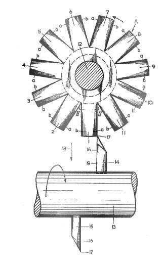
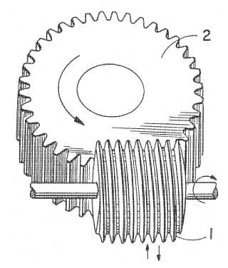
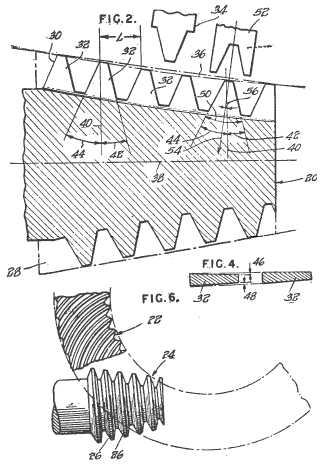
This place covers:
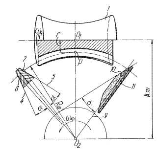
Methods and machines for manufacturing worm wheels, where worm wheels are the mating gears for worms. Both rough and finish machining are included.
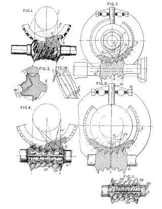
Example of manufacturing by hobbing (GB362448, Figure 4):
Attention is drawn to the following places, which may be of interest for search:
Making worms |
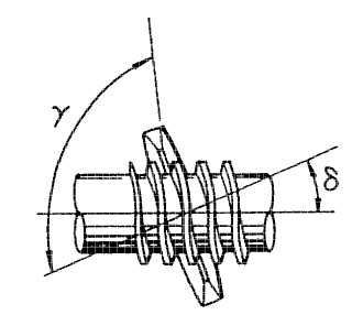
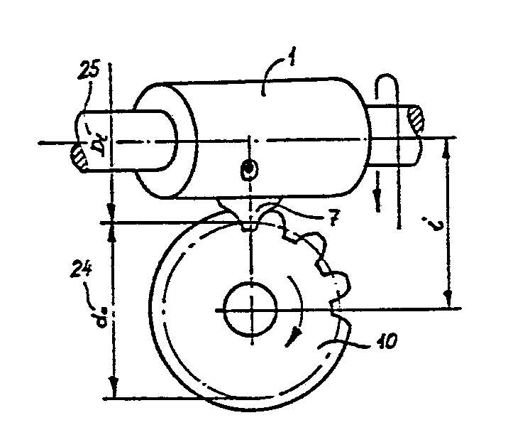
This place covers:
Machines and methods of the gear cutting type used for making worms. Both rough and finish machining are included.
Example (US5647703)
Attention is drawn to the following places, which may be of interest for search:
Making worm wheels |
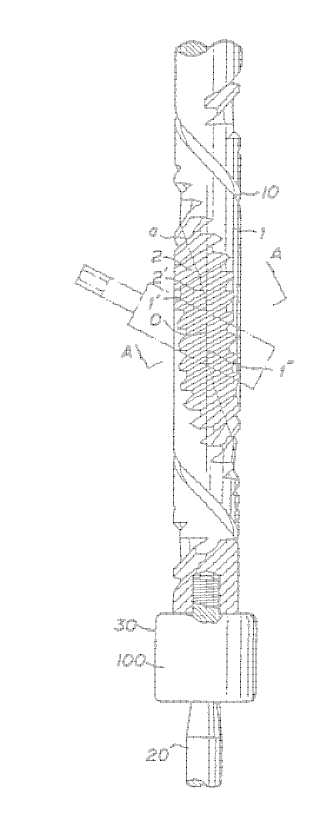
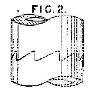
This place covers:
Methods and machines for making globoidal, e.g. hourglass shape worms.
Example (US3875635)
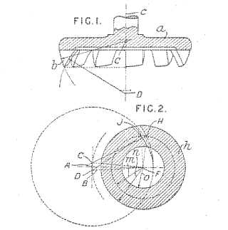
This place covers:
Methods and machines for special types of gear wheels and toothed members, e.g. sprockets, elliptical wheels, pump rotors, toothed clutches and face (crown) gears.
B23F 15/00 can be viewed as a catch-all group for gears or toothed members not covered by other groups in the subclass or by the subgroups of B23F 15/00.
Example (US4521141)
This place covers:
Methods and machines for making gear teeth on the front surface of wheels.
The front surface is generally understood to be a face surface that is transverse relative to the rotation axis.
Example, clutches (GB594492)
Example: Face gears (EP0906171):
This place covers:
Example (US4034645):
This place covers:
Special methods and machines for making gear teeth, not covered by other groups. Examples are methods and machines for making gear pairs, machines for machining tooth roots and machines which combine different machining operations.
This place covers:
Example (JP61117014):
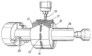
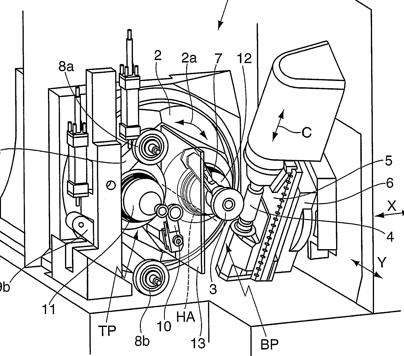
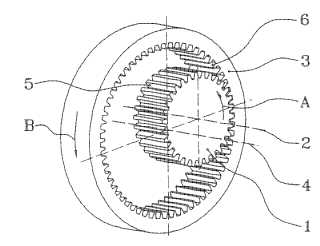
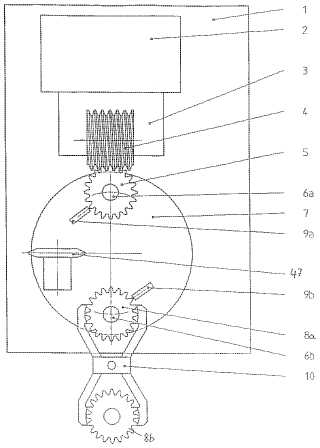
This place covers:
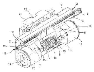
Example (DE2008034402)
workpiece (3), hob (4), cutting tools (7,10), chamfering tools (8a, 8b)
Attention is drawn to the following places, which may be of interest for search:
Arrangements for handling work with machine tools, in general |
This place covers:
Methods and machines for finishing gear teeth. The finishing process may include modifying the tooth form by crowning, by chamfering and by the provision of undercuts and stop notches. The group also includes deburring.
Example (EP1106290)
Methods and machines for finish grinding should be classified under the other grinding subgroups with the exception of cup-shaped grinding tools (B23F 19/005).
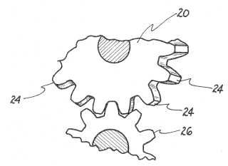
This place covers:
Example: (US5580298)
tool (24), workpiece (26)
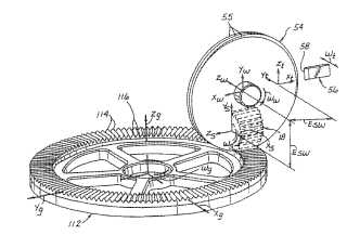
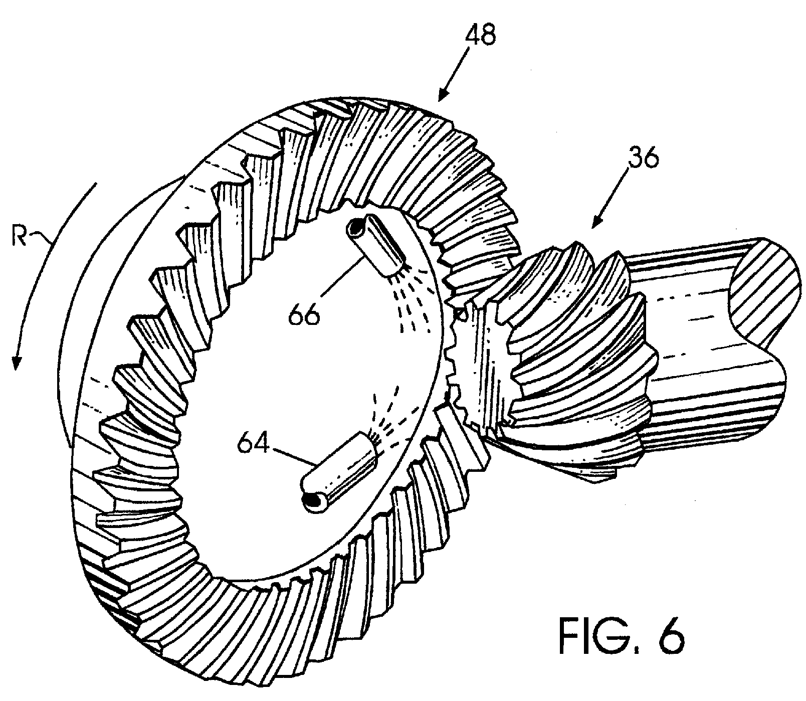
This place covers:
Example (US6217421)
workpieces (48,36), lapping compound supply means (64,66)
Attention is drawn to the following places, which may be of interest for search:
Lapping in general |
This place covers:
Example (US4077164)
tool (hone, 20), workpiece (26)
Attention is drawn to the following places, which may be of interest for search:
Honing tools for gear teeth |
This place covers:
Example (US3740904)
Attention is drawn to the following places, which may be of interest for search:
Honing worms for gear teeth |
This place covers:
Example (DE4317306)
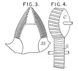
This place covers:
Example (GB801289):
tool (C, 33), workpiece (G)
Attention is drawn to the following places, which may be of interest for search:
Shaving cutters for gear teeth |
Attention is drawn to the following places, which may be of interest for search:
Shaving cutters in the shape of an internal gear |
This place covers:
Methods and machines for chamfering and deburring, including secondary deburring of the end edges of gear teeth.
Example (EP1022082)
Attention is drawn to the following places, which may be of interest for search:
Fly cutters for use in gear manufacture |
This place covers:
Included in this group are details of tools specially adapted for manufacturing gear teeth.
In this place, the following terms or expressions are used with the meaning indicated:
Inserted cutting elements | is understood as meaning that the tool has a body and cutting elements which take the form of inserts are fixed into the body. |
Inserted cutting elements in exchangeable arrangement | is understood as meaning that the inserted cutting elements can be removed and replaced by new inserts when required. |
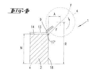
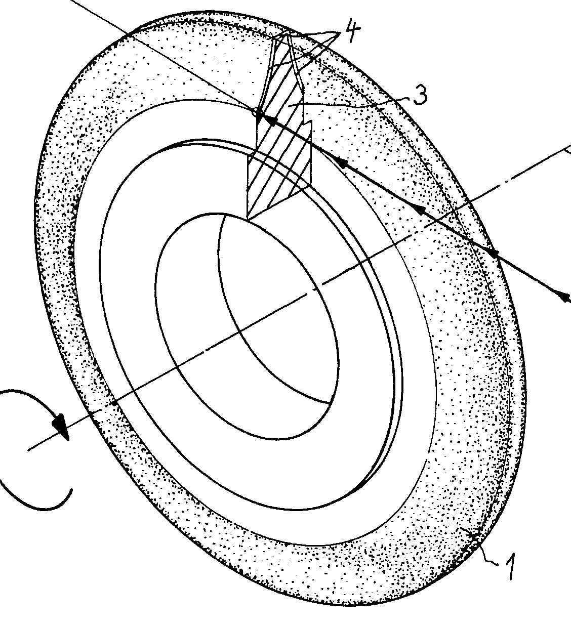
This place covers:
Example (US4533812):
grinding disc (1)
This place covers:
Example (EP1184122)
Attention is drawn to the following places, which may be of interest for search:
Making curved gear teeth with a cup-shaped grinding wheel |
This place covers:
Example (JP6297243):
Attention is drawn to the following places, which may be of interest for search:
Making straight teeth where the profile matches the profile of the required surface using a grinding worm | |
Generating straight teeth using a grinding worm |
This place covers:
Example (WO9924203)
Attention is drawn to the following places, which may be of interest for search:
Honing gear teeth |
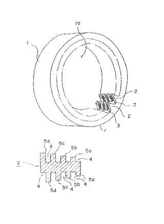
This place covers:
Example (US3740904)
Tool (1), workpiece (2)
Attention is drawn to the following places, which may be of interest for search:
Honing gear teeth with a honing worm |
Attention is drawn to the following places, which may be of interest for search:
Making straight teeth where the profile of the tool matches the profile of the required surface by planing or slotting |
This place covers:
Example (GB146769):
Attention is drawn to the following places, which may be of interest for search:
Making straight gear teeth using a rolling-off or enveloping motion by planning or slotting where the tool has the same profile as a tooth or teeth of a rack |
This place covers:
Gear shaper cutters having a shape similar to a spur wheel or part thereof, e.g. pinion cutters
Example (GB220192)
Attention is drawn to the following places, which may be of interest for search:
Attention is drawn to the following places, which may be of interest for search:
Milling cutters, in general |
Attention is drawn to the following places, which may be of interest for search:
Making straight teeth involving moving a tool relatively to a workpiece with a rolling-off motion by milling using a tool that has a shape similar to that of a gear or part thereof, with cutting edges situated on the tooth contour lines |
This place covers:
Example (JP59001120):
Attention is drawn to the following places, which may be of interest for search:
Hobbing straight gear teeth | |
Hobbing curved gear teeth |
This place covers:
Example (EP0088807):
tool (7), workpiece (10)
This place covers:
Example (GB 473050):
Attention is drawn to the following places, which may be of interest for search:
Making curved gear teeth by face milling | |
Making curved gear teeth by face hobbing |
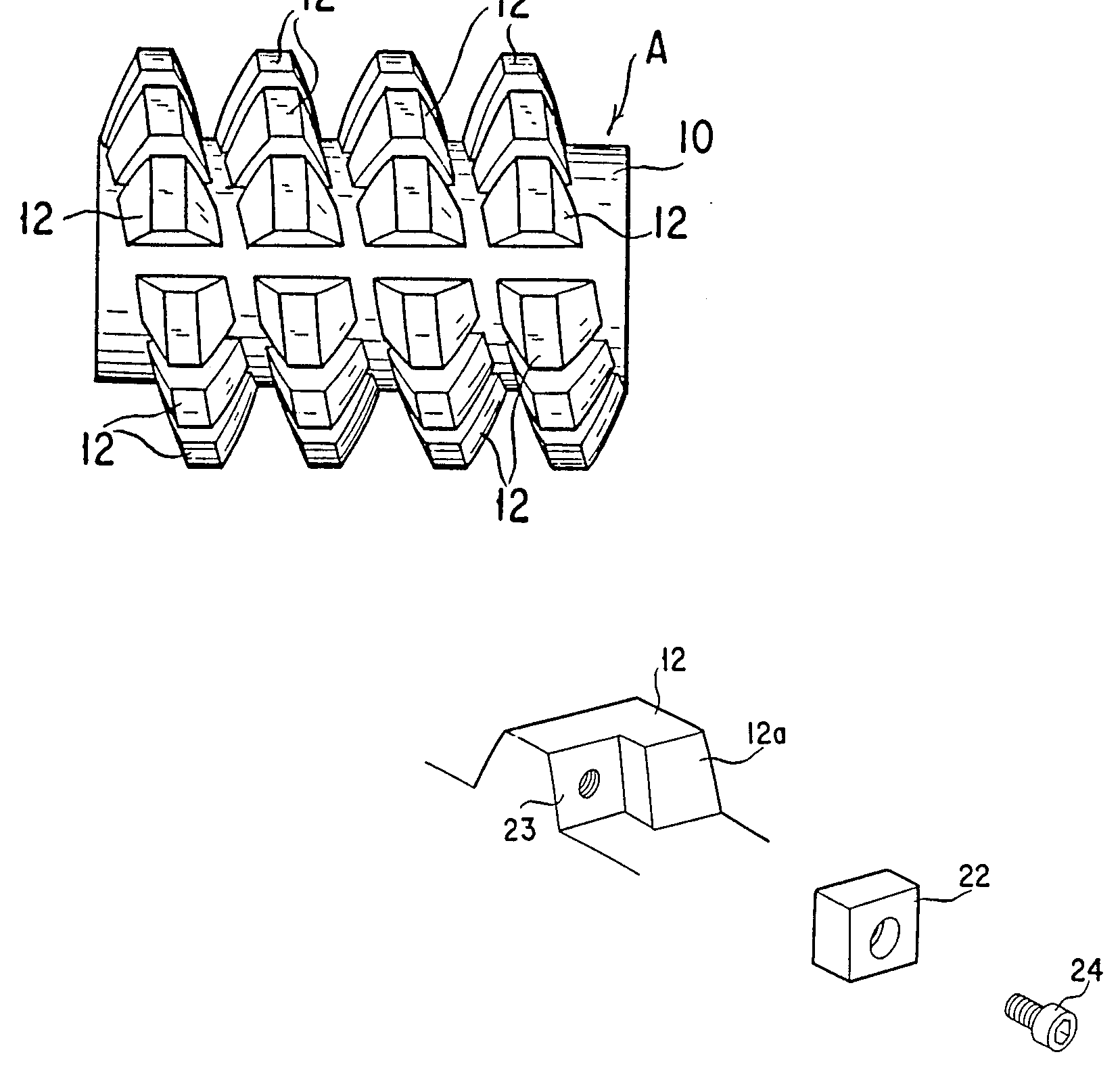
This place covers:
Examples:
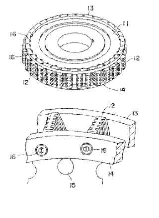
Face milling cutter (US3571876)
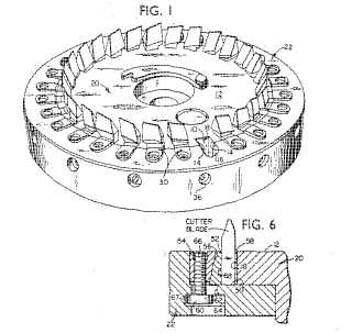
Face milling cutter for face hobbing (US6609858):
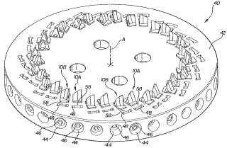
Milling tools with teeth arranged on a spiral curve are classified here, regardless of whether continuous generating is explicitly mentioned.
This place covers:
Example (GB364012):
Attention is drawn to the following places, which may be of interest for search:
Broach-milling of gear teeth using a tool whose profile matches the profile of the required surface | |
Broach-milling straight teeth involving a rolling-off motion |
This place covers:
Broaching refers to the removal of material in the form of chips from a workpiece by a relative movement between a tool having multiple teeth and a workpiece along a non-circular trajectory. The difference in height between successive teeth on a broaching tool determines the feed and hence the chip thickness
Example (US20040109731)
Attention is drawn to the following places, which may be of interest for search:
Broaching gear teeth using tools where the profile matches the required surface profile | |
Broaching straight teeth using a rolling-off motion | |
Broaching curved gears |
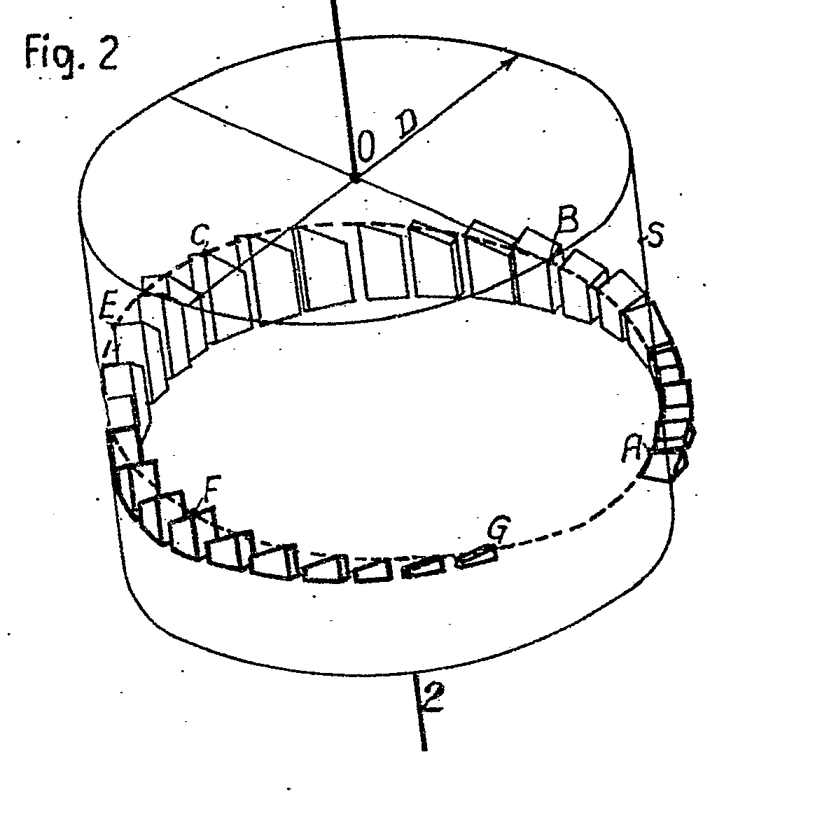
Attention is drawn to the following places, which may be of interest for search:
Broaching straight teeth with tools mounted on endless belt or chain | |
Broaching curved teeth with tools mounted on an endless belt or chain |
Attention is drawn to the following places, which may be of interest for search:
Pot broaching using tools whose profile matches that of the required surface |
This place covers:
Example (JP62114817):
Attention is drawn to the following places, which may be of interest for search:
Shaving gear teeth |
This place covers:
Example (JP61030322):
Attention is drawn to the following places, which may be of interest for search:
Shaving gear teeth using a tool in the shape of an internal gear |
This place covers:
Accessories and equipment specially designed to form part of gear cutting machines, e.g.
- generating, indexing and synchronising mechanisms
- loading, unloading and work holding equipment
- Tool holders
- Dressing arrangements for grinding wheels
Examples:
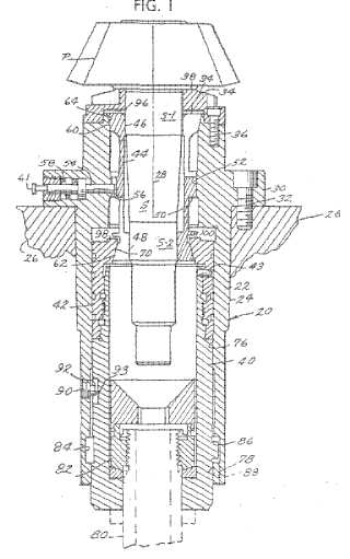
Tool / workpiece contact detecting device (US20030002943)
Loading / unloading (US6565418):
This place covers:
Example (US20050055836):
Attention is drawn to the following places, which may be of interest for search:
Numerical control (NC) of machine tools in general |
This place covers:
Example (GB1394518)
Attention is drawn to the following places, which may be of interest for search:
Handling work in machine tools in general |
This place covers:
Example (GB1256167):
Attention is drawn to the following places, which may be of interest for search:
Chucks, in general |
Attention is drawn to the following places, which may be of interest for search:
Automatic control and compensation for machine tools, in general |
This place covers:
Tool mountings refers to devices, or parts of devices for mounting or clamping the tool, for example (but not limited to) arbours or mandrels, such that the tool can then be held by a tool holder which connects the cutting tool to the machine tool.
Attention is drawn to the following places, which may be of interest for search:
Workpiece mounting, e.g. chucking arrangements | |
Gear cutting tool holders |
This place covers:
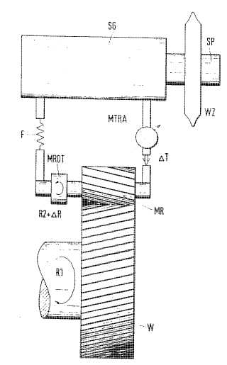
Example (US5174070):
Attention is drawn to the following places, which may be of interest for search:
Measuring arrangements using mechanical means for measuring contours of gears | |
Measuring arrangements using electrical or magnetic means for measuring contours of gears | |
Testing of gearings |
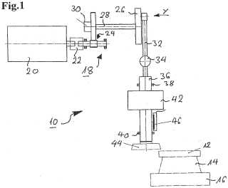
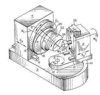
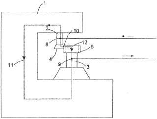
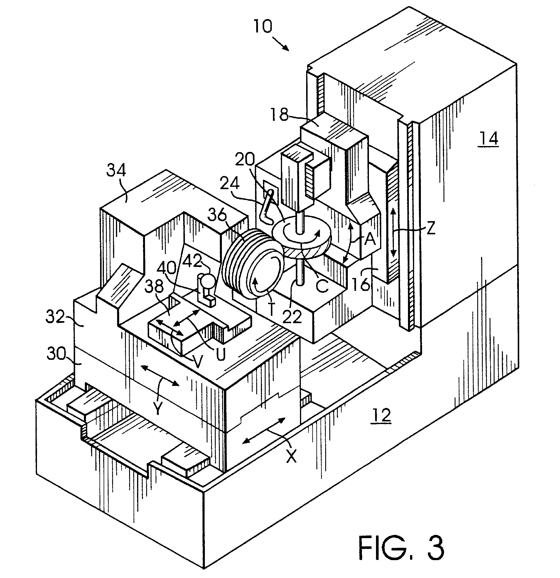
This place covers:
Example (US217409
workpiece (20), tool (36), dressing tool (42)
This place covers:
Example (JP20060035421)
This place covers:
Example (DE1020090039752)
Attention is drawn to the following places, which may be of interest for search:
Hobs for manufacturing gear teeth |
Attention is drawn to the following places, which may be of interest for search:
Face-milling tools for cutting curved teeth |
Attention is drawn to the following places, which may be of interest for search:
Planing or slotting tools having the same profile as a tooth or teeth of a rack |
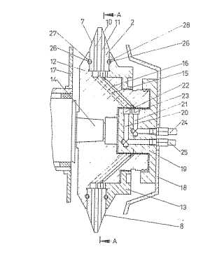
This place covers:
Example (DE3415498):
Attention is drawn to the following places, which may be of interest for search:
Grinding discs for use in gear manufacturing machines | |
Profile cutters of disc type for use in gear manufacturing machines | |
Securing milling cutters to the driving spindle, in general |
Attention is drawn to the following places, which may be of interest for search:
Face mill type grinding wheels for use in gear cutting machines |
In patent documents, the following words/expressions are often used as synonyms:
- " Face mill type grinding wheel" and "cup-shaped grinding wheel "
Attention is drawn to the following places, which may be of interest for search:
Grinding worms for use in gear manufacturing machines | |
Honing worms for use in gear manufacturing machines |
Attention is drawn to the following places, which may be of interest for search:
Honing tools for use in gear manufacturing machines | |
Shaving tools for use in gear manufacturing machines |
Attention is drawn to the following places, which may be of interest for search:
Pinion shaped cutters for use in gear manufacturing machines |