CPC Definition - Subclass B23B
This place covers:
Turning, lathes and related equipment, turning tools, tool holding systems, chucks, boring, boring tools, drilling machines and equipment, drilling tools.
Turning and boring are taken as being the removal of chips by the relative rotation of tool and workpiece wherein the cutting edge describes a substantially continuous spiral or helical path with respect to the workpiece.
B23B covers features of the machine/tool/process specifically related to turning or boring of metal or metal-like materials. Features not relating to the specific process of turning or boring but applicable to more general machines/processes will be classified elsewhere. Features relating to the turning and boring of materials other than metal will only be classified in B23B if the content of such documents renders them applicable to metal cutting (i.e. where the intrinsic properties of the non-metallic material are not important).
This place does not cover:
Drills bits and machines for surgery, chucks and guiding devices therefor | |
Tools for dentistry | |
Drilling machines combined with arrangements for riveting | |
Orbital drilling by milling | |
Multi stage processes involving turning & boring and other operations such as making particular items by multistage processes, once of which is turning/boring or drilling. | |
Making turning, drilling or boring tools | |
Details of machine tools and accessories not related to the operation being performed including: | |
Clamping systems for workpiece tables | |
- tool changing | |
- conveying workpiece into and from machine | |
- evacuation of swarf, | |
- guarding & protective coverings | |
Adaptive control and/or computer controls for turning, boring or drilling processes | |
- measuring or sensing | |
Control systems and devices for copying from a master template or patterns | |
Details of powered hand tools not related to the drilling operation | |
Drill stands | |
Turning, boring or drilling of wood | |
Turning, boring or drilling of stone and glass | |
Cutting inserts characterised only by the composition of the hard metal material | |
Cutting inserts characterised only by the composition of the diamond cutting material | |
Cutting insert characterised only by the composition of the coating | |
Drilling of earth or rock |
Attention is drawn to the following places, which may be of interest for search:
Cleaning | |
Production by reshaping | |
Sintering | |
Shearing of metals | |
Sawing | |
Making gears | |
Grinding and production of lenses. | |
Drill stands | |
Cutting of non-metals by severing | |
Working of plastics | |
Ceramic products | C04C |
Hard metal, composition of CBN compacts | |
Diamonds | |
Coatings | |
Connections of hubs and shafts | |
Supports for workpieces | |
Numerical control | |
Motors |
A 2000-series Indexing Code system exists within B23B for deep indexing of tool characteristics and classification of useful information. The use of Indexing Codes from the 200-series is widespread in the subclass and these Indexing Codes should be allocated at every opportunity. When classifying, the Indexing Codes relating to a particular group or subgroup should be consulted and allocated if appropriate, taking precedence over similar Indexing Codes present within the whole subclass. For example, if classifying in B23B 31/20 or subgroups, the Indexing Codes relating to the details of collet chucks should be consulted and allocated to provide additional information. If classifying in the group B23B 31/00, the Indexing Codes relating to details of chucks should be consulted and these Indexing Codes allocated to provide additional information The number of Indexing Codes is too high to list individually. Where the allocation of Indexing Code-codes is mandatory (most notably within the subgroups containing cutting inserts, B23B 27/14 and B23B 27/16), this is indicated in the templates for the main-group at the sub-group level.
In the Indexing Code system the term "discontinuous" is used to mean containing points or lines of inflection or gaps.
Pictorial examples of the content of the most widely used subgroups have been provided within this FCR. Each of the drawings is taken from a document classified in the subgroup, for which it serves as an example. No copyright is claimed.
This place covers:
Methods of turning, wherein the method relates to the actual process of turning. Illustrative examples:
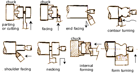
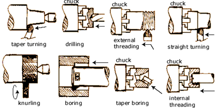
Turning types (Source: DeGarmo, P. et. al, "Materials & Processes in Manufacturing", Macmillan, New York, 1984).
If a document relates simply to the production of an item by turning and the turning process per se is known, the document will not be classified in B23B 1/00 but instead be classified with the product itself.
This place covers:
General-purpose turning-machines or devices and sets of turning-machines.
Illustrative examples:
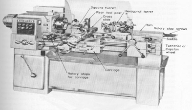
B23B 3/00 - General purpose turret lathe (B23B 3/161) (Source: DeGarmo, P. et. al, "Materials & Processes in Manufacturing", Macmillan, New York, 1984).
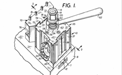
B23B 3/22 and subgroups. Lathe with rotary head (clamshell lathe) (Source: US 4 944 205).
Most documents relating to turning machines are classed in B23Q for features relating to the construction of the machine and its components e.g. beds in B23Q 1/015. Documents pertaining to lathes should therefore be routinely circulated to B23Q as well as being classed in these groups. Searches in B23B 3/00 - B23B 11/00 cannot be considered exhaustive without search in B23Q.
Important classes are B23B 3/06(B) for special arrangement of units on lathes in general and B23B 3/161, B23B 3/162, B23B 3/164, B23B 3/165, B23B 3/167 & B23B 3/168 for arrangements of turret lathes. The turret here refers to a turret for holding tools (see notes on B23B 3/30 for workpiece turrets).
Clamshell lathes (one part fixed to cylindrical workpiece and another part with tool orbits the workpiece) are classed in B23B 3/22 and subgroups. The rotary tool heads of B23B 3/22 should be considered as a head that rotates to provide the main cutting motion in the turning process. The term "radial" in the titles of B23B 3/24 and B23B 3/26 refers to the radial direction with respect to the rotational axis of the tool head.
B23B 3/30 is not much used as multi-spindle lathes are systematically classed in B23Q 39/042 (drum arrangement) and B23B 39/22 (opposed headstock arrangement).
Note for groups B23B 3/00 - B23B 11/00:
There is no systematic classification in most of these groups just for the fact that the machine is a lathe. That is to say, not every lathe is classed in the groups by virtue of just being a lathe. For instance if the inventive features relate to general constructional elements of the lathe and the fact that these features are present on a lathe is of secondary importance, the document will only receive a class in the appropriate sub-group(s) of B23Q. If the control is of particular importance, the document will only receive a class in G05B. If the document relates to copying arrangments on lathes it will only receive a class in B23Q 35/00, unless a particular feature of the lathe itself is of interest.
Classification in these groups is per literal interpretation of the title of the group and sub-group headings.
This place covers:
Turning machines or devices that are specially adapted for particular work and accessories specially adapted for particular turning work, including:
- lathes for working Pilgrim (Pilger) rolls (B23B 5/10)
- peeling machines (B23B 5/12).
- hand-held, bench mounted or workpiece mounted devices for working the ends of bars tubes and electrodes (B23B 5/16). If such a tool is combined with a severing tool B23D 21/006. If milling is performed classification in B23C 3/007 and/or B23C 3/122 may be appropriate.
- machines for turning wheel-sets on trains (B23B 5/28).
- devices to turn specially shaped surfaces (B23B 5/36) through geometrical mechanisms, especially the surfaces mentioned in the subgroups. Note turning of polygonal surfaces is usually classed in B23Q 27/00.
- machines for turning cam shafts or crankshafts (B23B 5/18). Note B23C 3/06 & B23C 3/08 and B23D 37/005 for milling and broaching of crankshafts and camshafts. Illustrative examples:
B23B 5/12 Peeling machine (Source: US 2006/0266172).
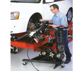
B23B 5/04 Brake lathe for vehicles (Source: www.efi.com.au/hunter/brake_lathe_on_car.html).
B23B 5/10 Pilgrim (Pilger) roll lathe Note: Pilger rolling mills are classed in B21B 21/00 (Source:FR40388E).
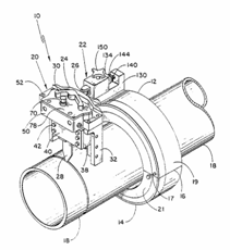
B23B 5/162 Pipe bevelling device attached to workpiece (Source: US 6 755 101).
B23B 5/166 Electrode tip dressing device (Source: WO 2006/043867).
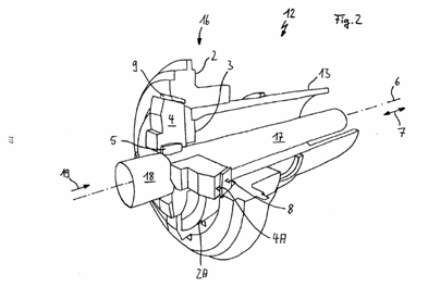
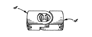
B23B 5/168 Tube chamfering device with guide (4) (Source: DE 202006007258 U).
Systematic classification required in B23B 5/00.
Classification in these groups is per literal interpretation of the title of the group and sub-group headings.
This place covers:
automatic or semi-automatic turning-machines with a single working-spindle; equipment therefor; features common to automatic and semi-automatic turning-machines with one or more working-spindles, including
- lathes for turning of stock (B23B 7/02). Stock is to be interpreted as "bar stock", i.e. an elongate piece, from which a multiplicity of components are produced.
- lathes for turning of stock with tool turrets (B23B 7/04). Note that lathes with workpiece turrets will be classified in B23Q 39/042 .
- lathes for turning of stock with a sliding headstocks (B23B 7/06)
- lathes for turning individual workpieces (B23B 7/12). The term "for turning individual workpieces" is to be interpreted as in which a piece of material is used to produce a single component.
In this case "automatic" is not to be interpreted as limited to NC.
Illustrative example:
B23B 7/06 Sliding headstock lathe (Source: EP 2030707).
Further details of subgroups
B23B 7/06 is important as this group covers sliding headstock machines.
There is no systematic classification in B23B 7/00 just for the fact that the machine is a lathe. That is to say, not every lathe is classed in the groups by virtue of just being a lathe. For instance, if the document mainly relates to a general constructional element applicable to many types of a machine tool, but is shown on a lathe, the document may only be classed in B23Q. See notes to B23B 3/00.
Classification in these groups is per literal interpretation of the title of the group and sub-group headings.
In this place, the following terms or expressions are used with the meaning indicated:
Stock | bars from which multiple workpieces are made |
This place covers:
Automatic multi-spindle machines.
Refer to B23Q 39/042 for multi-spindle machines with spindles arranged parallel to each other in a drum and B23B 39/22 for machines where the headstock and tailstock both have spindles.
This group is hardly used as the systematic classification of multiple spindle lathes has traditionally been done in B23Q 39/00.
There is no systematic classification in B23B 9/00 just for the fact that the machine is a lathe. That is to say, not every lathe is classed in the groups by virtue of just being a lathe. Please refer to notes on group B23B 3/00.
Classification in these groups is per literal interpretation of the title of the group and sub-group headings.
Usually lathes with live tooling will be classified in B23B 3/065, B23B 3/162, B23B 3/165 or B23B 3/168.
This place does not cover:
Arrangements for performing other machining operations, e.g. milling, drilling | |
Turret lathes for turning individually-chucked workpieces |
This group is hardly used as this is now commonplace.
There is no systematic classification in B23B 11/00 just for the fact that the machine is a lathe. That is to say, not every lathe is classed in the groups by virtue of just being a lathe. See notes under B23B 3/00.
Classification in these groups is per literal interpretation of the title of the group and sub-group headings.
This place covers:
Arrangements for conveying and feeding stock (bar feeders). Illustrative examples:
B23B 13/02 Single spindle lathe bar feeder (Source: DE 102004043797).
B23B 13/04 Multi-spindle lathe bar feeder (Source: GB 1358424).
This group relates to mechanism for feeding and conveying bars. B23Q 7/00 deals with supply of individual workpieces to a machine. B23Q 7/00 also deals with supplies of non-rotating bars to other types of machine. In lathes (and therefore to qualify for classification in B23B 13/00) the feeding mechanism must allow the bar to be driven in rotation.
Classification is defined by the literal interpretation of the groups.
B23B 13/022 "being placed in the spindle" should be interpreted as being part of the machine tool spindle.
B23B 13/024 is used for devices with a feeding device that is located in the machine tool spindle with two collets, wherein usually one collet is movable longitudinally. The other collet grips the stock whilst the first collet is moving away from the machine headstock. When the movable collet has gripped the stock, the seoond collet opens two allow the stock to be advanced.
Collets for bar pushers are classed in B23B 13/123, collets in general are classed in B23B 31/20.
This place covers:
Tailstocks and centres for turning machines
Illustrative examples of subject matter classified in this group:
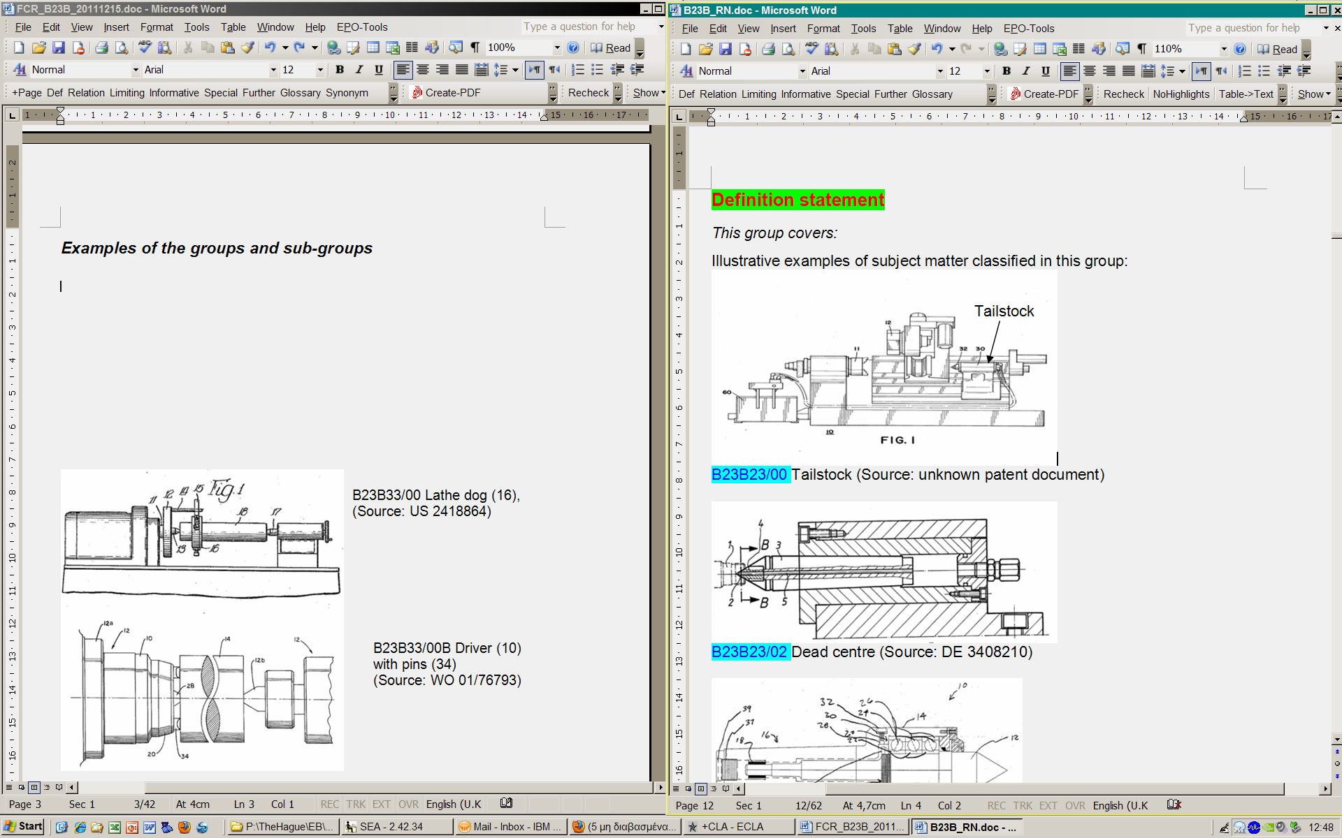
B23B 23/00 Tailstock (Source: unknown patent document).
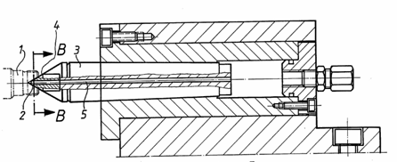
B23B 23/02 Dead centre (Source: DE 3408210).
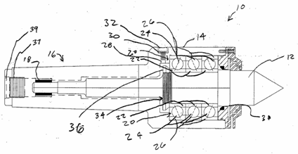
B23B 23/04 Live centre (Source: US 2006/0037444).
Classification is generally per literal interpretation of the group and subgroup headings.
In this place, the following terms or expressions are used with the meaning indicated:
Live centre | one that rotates with the work |
Dead centre | one that supports the work and allows the workpiece to rotate relative to it |
This place covers:
Accessories or auxiliary equipment specially designed for use on turning-machines.
B23Q 11/08 takes priority for protective covers and so documents for B23B 25/04 should be routinely offered to B23Q as they are usually classified there, rather than in B23B 25/04.
Special rules of classification within this group
In order to classify in B23B 25/06 the measuring system should be applicable only to turning machines. B23Q 17/00 relates to measuring on machine tools in general and takes preference over B23B 25/06. Since problem of setting tool height relates only to turning machines, class B23B 25/065 is used.
As chip-breaking is usually done by insert (e.g. B23B 27/143), by tool holder clamp (e.g. B23B 27/1629) or by tool holder itself (B23B 27/22) chip-breaking equipment classed in B23B 25/02 is rare.
This place covers:
Tools for turning. The tool is interpreted to be the component containing the cutting edge.
Illustrative examples:
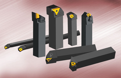
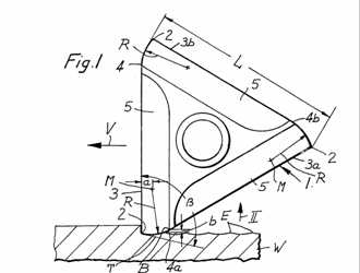
B23B 27/00 and B23B 29/00 tools and tool holders (Source: unknown book or catalogue).
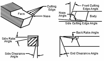
B23B 27/00 tool surface nomenclature (Source: unknown book).
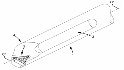
B23B 27/007 Tool for internal turning (Source: EP 1806191).
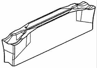
B23B 27/045 Parting off tool with chipbreaking features (Source: EP 2060347).
B23B 27/065 Thread cutting turning insert (Source: EP 0804313).
B23B 27/083 Tool with disc-like main part fitted with parting off insert (ref 5,6 see B23B 27/04) (Source: EP 2082820).
B23B 27/10 Turning tool with cooling (Source: WO 2007/145649).
B23B 27/141 (and B23B 2226/315) Cutting insert with PCD cutting edge (Source: DE 10216408).
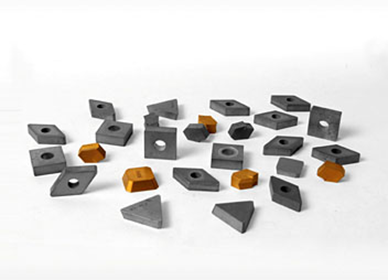
B23B 27/141 Cutting inserts (Source: http://0086exporter.en.made-in-china.com/product/gonEdzACYShQ/China-Carbide-Indexable-Insert.html).
B23B 27/141 Double sided cutting insert (Source: BE 716819).
B23B 27/141 (and B23B 2200/205) Cutting insert with wave-form cutting edge (Source: WO 93/11898).
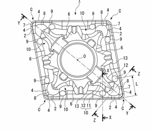
B23B 27/141 (and B23B 2200/0447, B23B 2200/081) Parallelogram insert with chip-breakers (Source: EP 1454690).
B23B 27/141 (and B23B 2200/208) Triangular insert with wiper (corner geometry) (Source: GB 2104421).
B23B 27/1614 (for special shaped) or B23B 27/1662 (for standard shaped) (and B23B 2200/3618 for special fixation hole) Insert clamped by member acting on hole wall (Source: WO 2009/028744).
B23B 27/1625 (for special shaped) or B23B 27/1666 (for standard shaped). Insert clamped by member acting on top face (Source: DE 7614471U).
B23B 27/1644 (for special shaped) or B23B 27/1677 (for standard shaped). Insert simultaneously clamped by hole and top clamps (Source: GB 1395578).
B23B 27/1655 (for special form) or B23B 27/1681 (for standard form). Adjustable position of the insert (Source: WO 02/24387).
Further details of subgroups
This sub-group includes grooving tools.
See also B23B 27/08 when tools have a blade-like main part.
Limited use with the introduction of NC.
Cooling arrangements. Cooling arrangements in drilling tools B23B 51/06, in milling tools B23B 5/28 and in reaming tools B23D 77/006. Cooling arrangements in machine tools B23Q 11/10. To be classed in B23B 27/10 the cooling arrangement must be present in the tool (including the toolholder) itself.
Tools with continuously rotating cutting edge.
Some milling tools with circular cutting edges that rotate during use are classed here too.
Allocation of Indexing Codes from the 2000-series section relating to "details of cutting inserts" is mandatory in B23B 27/14 and B23B 27/16.
200-series Indexing Codes should be allocated only for special features of the insert.
Cutting tools where the cutting insert is of special importance.
Inserts in this subgroup are not classed for composition of inserts (C22C or C04C) or for the composition of the coating (see C23C) despite the class B23B 27/148.
B23B 27/141 has inserts having a special shape and chip-breakers. Inserts having a special shape but not chip-breaker details are classed in B23B 27/145. Inserts having a special shape by virtue only of the chip-breakers are classed in B23B 27/143. Thus search in at least two of these sub-groups is always necessary.
B23C 5/202 is the equivalent group for milling inserts.
If insert can be used for turning and milling only a class in B23B 27/141 is given.
If method of clamping the insert in the tool-holder is also important, no class is given in B23B 27/141, only in B23B 27/16.
Securing arrangements for inserts.
If insert is also special shape, it will be classed in B23B 27/1603 and subgroups, B23B 27/1614 and subgroups, B23B 27/1625 and subgroups, B23B 27/1644 and subgroups or B23B 27/1655 (e.g B23B 27/1614 contains inserts of special shape having chip-breakers that are clamped against the walls of the pocket of the holder by something acting on the wall of a hole in the insert, B23B 27/1618 contains inserts where the special shape concerns the chip-breakers but where the clamping is still important). If the special clamping system does not fall under B23B 27/1614, B23B 27/1625, B23B 27/1644 or B23B 27/1655, the document should be classed in B23B 27/1603.
Special Clamping of known shaped cutting inserts is in B23B 27/1659 - B23B 27/1685.
Permanently fixed bits or tips including B23B 27/20 (solid) diamond tools, which does not relate to PCD coated tooling.
Knurling tools
Note B23P 9/02 - finishing by knurling.
What are commonly called "boring bars" in tool catalogues are classified in B23B 27/007 as tools for internal turning (tools usually not used when placed coaxially with central axis of the hole being produced but parallel to it).
Classification is per literal interpretation of the groups.
Classification is generally per literal interpretation of the group and subgroup headings.
In this place, the following terms or expressions are used with the meaning indicated:
Boring bars | bars that are aligned on the axis of the hole being produced whilst either the work or the bar itself is rotated. |
Tool | the component containing the cutting edge |
This place covers:
Holders for turning tools.
The tool is generally interpreted to be component containing the cutting edge. A strict literal interpretation of this statement would mean that in a cutting tool with an indexable insert, the insert is considered as the tool per se and the insert holder (shank) is considered as the holder. In the case of holders for single tool this is generally the case. However the consideration of the insert and shank should not be precluded from being considered as the tool, i.e. a holder (especially in B23B 29/046 and B23B 29/24) can be a holder for holding a combination of a cutting insert and a shank. Thus turning tool holders for multiple tools can be considered as including non-rotating holders for more than one cutting insert and holders to retain multiple instances of insert/holder combinations.
Illustrative examples of subject matter classified in this group:
B23B 29/02 Boring bar for boring bearing surfaces in internal combustion engine (B23B 41/12) (Source: EP 1084783).
B23B 29/03428 Boring head radially adjustable by an eccentric prior to work (Source: WO9402275). The term "radially" should be interpreted as relative to the rotation axis, which will normally be for the purpose of altering the size of the diameter to be machined.
B23B 29/0345 Boring head adjustable during operation (outfeeding bar) by means of inclined planes (42) (Source: US 5211088).
B23B 29/0345 Facing head adjustable radially during manufacture by means of inclined planes (Source: US 5795114).
B23B 29/043 (and B23B 2205/02) Parting off toolholder with elastic clamping member. (Note: cutting insert classed in B23B 27/04 or B23B 27/045) (Source: WO 2004/062839).
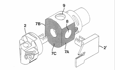
B23B 29/046 Modular tool system with two alternative intermediary toolholders (2,2') (Source: WO 9911411).
B23B 29/125 Toolholder (20) including vibratory mechanism (24). (Source: US 2006/051480).
B23B 29/20 Arrangements to support toolholders (30) in turret (62) (Source: US 5875696).
B23B 29/242 Toolholder for a plurality of tools acting as turret (Source: US 2006/0104728).
B23B 29/242 Turrets insofar as arrangement of tools and attachment of tools to turret is important (Source: EP 1671728).
B23B 29/244 Toolpost for plurality of toolholders (Source: US 4126067).
Further details of subgroups
Boring bars are usually bars held on the centreline of rotation. What are termed "boring bars" in tooling catalogues are actually considered to be turning tools for internal turning and classified in B23B 27/007.
Boring or facing heads, grooving tools or other tools that can be set to machine a certain diameter or that can be adjusted to different cutting diameters during machining. The term "radially" should be interpreted as relative to the rotation axis, which will normally be for the purpose of altering the size of the diameter to be machined. Facing heads are widely used.
Note boring of valve seats B23C 3/05.
Holders for parting off and grooving tools.
Holders including details of modular systems (e.g. Capto, block tooling) that allow one piece of tool assembly only to be exchanged.
Special arrangements on turning tools e.g. vibratory tool-holders, support for workpiece, location of tool in a turret.
Toolholders for a plurality of tools. The indexing mechanisms and drives for rotating tooling for turrets are classified in B23Q.
Where features relate to retention of tools, turrets are classed in B23B 29/24.
Tool posts are used on more old style lathes and are (usually vertical) posts with (usually) 4 stations which index into position.
Also includes turrets where the details of the location or clamping of holders for rotary tools is important.
This place does not cover:
Cutting tools with special provision for cooling with a continuously-rotated circular cutting edge; holders therefor |
Within the context of B23B 27/00 and B23B 29/00, the term "boring bar" is taken to mean a bar that is aligned on the axis of the hole being produced, whilst either the work or the bar itself is rotated.
Classification is per literal interpretation of the group and sub-group headings.
In this place, the following terms or expressions are used with the meaning indicated:
Boring bars | bars that are aligned on the axis of the hole being produced whilst either the work or the bar itself is rotated. |
Tool | component containing the cutting edge |
This place covers:
Chucks, expansion mandrels, adaptations of chucking arrangements for remote control, details of shanks of tools insofar as they are not related to the operation being performed but to the clamping of the tool. Chucks are devices for holding tools or workpieces suitable for use on machine tools. Note B23Q 3/00 contains work holding devices for mounting workpieces to a workpiece table.
Illustrative examples of subject matter classified in this group:
B23B 31/028 Chuck with axially movable stop (9) to set tool length.
B23B 31/103 Chuck with pivotal element (42).
B23B 31/1075 Chuck with screw detent.
B23B 31/1078 Chuck with laterally acting wedges.
B23B 31/113 Chuck with bayonet connection.
B23B 31/117 Chuck with spiral needle rollers retains by friction only.
B23B 31/1179 Chuck for tools using heat shrink technique.
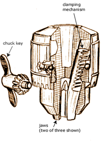
B23B 31/1238 Chuck with inclined jaws actuated by nut operated by a key.
B23B 31/1246 and B23B 2231/38 Keyless chuck with inclined jaws activated by central bolt (18) with conical screw thread.
B23B 31/1253 and B23B 2231/38 chuck with inclined jaws (4) operated by an axially movable member (24).
B23B 31/117 Chuck with retention by friction only.
B23B 31/1107 Chuck with threaded connection for conical parts.
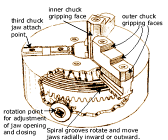
B23B 31/16004 Chuck with simultaneous radially acting jaws actuated by spiral groove.
B23B 31/16016 or B23B 31/16058 or B23B 31/16095 or B23B 31/16133 or B23B 31/1617 or B23B 31/16208 or B23B 31/16245 or B23B 31/16279 Chuck with radially acting jaws including special fixation of top jaws (2) onto master jaw (4).
B23B 31/16083 Chuck with radial jaws actuated simultaneously by gears and racks.
B23B 31/1612 External chuck with radially acting jaws (69) actuated by cam (65) in radial plane. B23B 31/4093.
B23B 31/16045 Chuck with simultaneous radially acting jaws (4) actuated by an oblique rack (5,7).
B23B 31/16195 and B23B 31/14 Chuck with radial jaws (22) actuated by levers (40) activated by coaxial control rod (42) with counterweights (16c) to counteract centrifugal force.
B23B 31/16033 or B23B 31/16075 or B23B 31/16112 or B23B 31/1615 or B23B 31/16187 or B23B 31/16225 or B23B 31/16262 or B23B 31/16283 or B23B 31/16291 Chuck with radially acting jaws and a centre (84).
B23B 31/16045 Chuck with simultaneous radially acting jaws (5) actuated by screws and nuts.
B23B 31/16241 Chuck with jaws (4) actuated by oblique surfaces (11, 12) on coaxial control rod (3) with top jaws (4B) of special form.
B23B 31/16287 Chuck with simultaneously acting jaws (30) operated by fluid (12).
B23B 31/16158 Chuck with coaxial conical surfaces (11) actuating jaws (7,8)
(Source: DE 4222703).
B23B 31/18 Chuck with simultaneously pivoting jaws.
B23B 31/201 Collet chuck characterised by its operating mechanism.
B23B 31/22 Chuck with balls acting as jaws (not as detents
(Source: DE 102007060084).
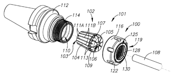
B23B 31/202 Collet chuck (Source: unknown book or internet).
B23B 31/261 Chuck using mechanical transmission through spindle (18) to grip end of toolholder shank (15).
B23B 31/302 Hydraulic equipment (110) for chucks.
B23B 31/305 Chuck with hydraulic clamping by deformable sleeve.
B23B 31/32 Chuck with diaphragm (14).
B23B 31/34 Chuck enabling workpiece to be reversed.
B23B 31/36 Chuck (13) with means (56, 66) to offset the chuck with respect to the working spindle.
B23B 31/39 Chuck jaw changer.
Further details of subgroups
See notes to B23B 31/117.
Includes chucks for shanks of tools.
Chucks using heat shrinking technology to hold the tool shank are classed in B23B 31/1179 . The machine used to assemble tools by heat shrinkage is classified in B23P.
Equipment for setting tools to a pre-set length (pre-setters and tool measuring devices) are classified in B23Q 17/24.
Features relating to removal of tool or work. See also B23B 31/003.
Yielding holders. Includes tapping holders in B23B 31/083.
Independent jaws (e.g. 4-jaw chucks).
Details of jaws but note that documents relating to details of jaws of chucks with simultaneously acting jaws are classed in B23B 31/16, which takes precedence.
Pivoting catches or pawls. Note pivotally movable jaws in plane containing the axis of the chuck is B23B 31/18.
Retention by lateral elements not acting as jaws (i.e. not providing a radial clamping force as the sole means of retaining the work or tool in the chuck).
In this subgroup pins are radially disposed, whereas cylindrical elements are circumferentially disposed.
Note difference between retention by screw B23B 31/1075 with radial screws and B23B 31/11 threaded connection, usually with axially aligned thread).
Note B23B 31/22 is when balls act as jaws.
Covers threaded connections with conical parts. The threads on these connections can be cylindrical or conical. The Indexing Codes for cylindrical and conical threads must be allocated where appropriate.
Clamping by friction only. Note heat shrink toolholders are classed in B23B 31/1179 . Chucks with deformable sleeve operated by hydraulics are classed in B23B 31/305.
"Jacobs" type chuck found on portable drills either keyless or not. If chuck is keyless, allocate B23B 2231/38. If details of chuck key are given allocate B23B 2260/078.
Chucks with radial jaws acting simultaneously.
Actuated by spiral groove.
Acuated by oblique rack.
Actuated by screws and nuts.
Actuated by gears and racks.
Actuated by cam in plane perpendicular to chuck axis
Actuated by coaxial conical surfaces.
Actuated by pivoting levers (bellcranks).
Actuated by oblique surfaces of coaxial rod (usually T-slots).
Jaw details important.
Note also B23B 31/16008, B23B 31/1605, B23B 31/16087, B23B 31/16125, B23B 31/16162 and B23B 31/162 where actuation mechanism is also known or important.
using fluid. Note also B23B 31/16025, B23B 31/16066, B23B 31/16104, B23B 31/16141, B23B 31/16179 and B23B 31/16216 where actuation mechanism is also known or important.
with a centre. Note also B23B 31/16033, B23B 31/16075, B23B 31/16112, B23B 31/1615, B23B 31/16187 and B23B 31/16225 where actuation mechanism is also known or important.
Means preventing the ejection of jaws.
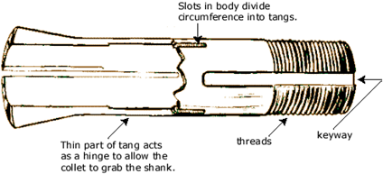
Collet chucks
Allocation of Indexing Codes from the section "details of collect chucks" is mandatory.
Collet chucks in devices designed to be attached to a machine tool table are classified in B23Q 3/067.
Collet chucks for bar pushers B23B 13/123.
Tool clamping mechanisms in machine tool spindles. Details of the spindle not concerning the clamping mechanism are classed in B23Q 1/70.
Hydraulic means.
Actuating cylinders for lathe chucks.
Chucks with deformable sleeve operated by hydraulics.
Adjusting chucks relative to working spindle. Adjustment of work/tool relative to chuck B23B 31/026.
Expansion mandrels. Note similarity in this group to externally acting 3-jaw self-centring chucks of B23B 31/16.
External collets.
Clamping between two plane surfaces. Documents showing an arbour type arrangement in which clamping is between two plane surfaces should be classed here, even if the arrangement does not have an expansion mandrel.
Where the area of interest is how to fix a chuck unit to a spindle, documents are classed in B23Q 3/12. it is foreseen that the pertinent documents will be placed in a new subgroup of B23B 31/00 shortly.
This place does not cover:
faceplates | |
Rotary devices holding by magnetic and/or electrical force acting directly on work | |
Allowing axial oscillation of percussion tool bits |
Where the important features of a tool relate to the shank (i.e. when it is unimportant what type of tool it is but more important how the tool is to be clamped) a class will be given in B23B 31/005 or B23B 31/006 .
Allocation of 2000-series Indexing Codes from the section "details of chucks", B23B 2231/00, including "collet chucks" B23B 2231/20, is mandatory in B23B 31/00.
Classification is per literal interpretation of the group or sub-group.
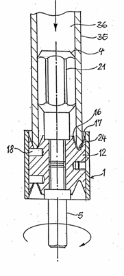
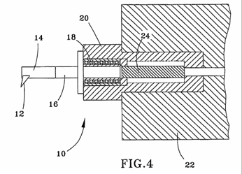
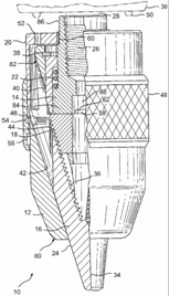
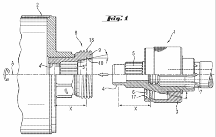
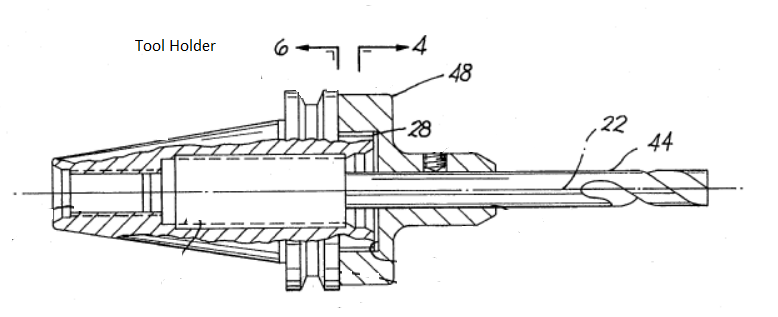
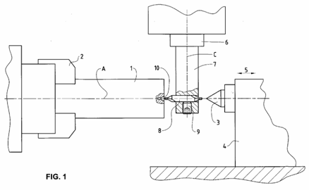
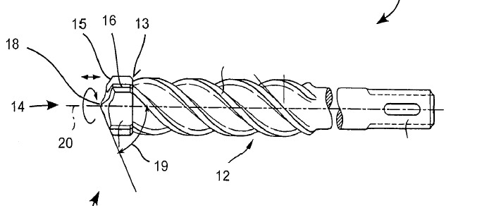
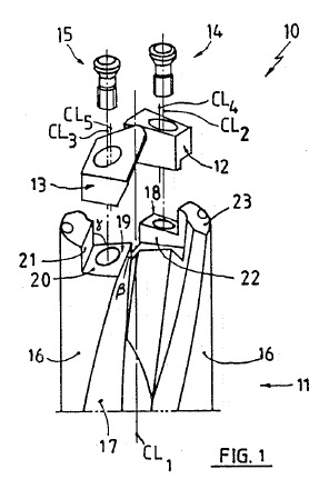
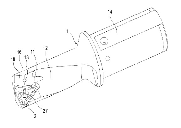
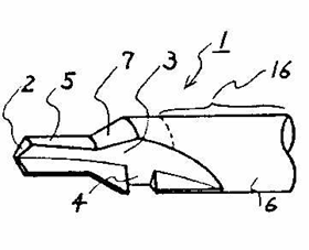
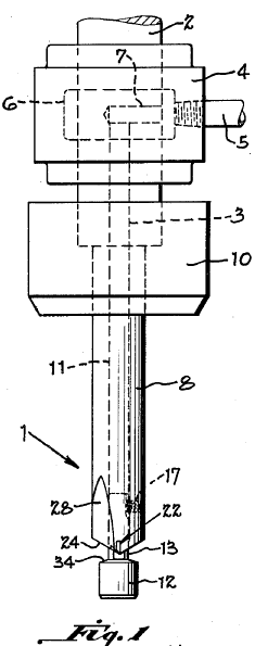
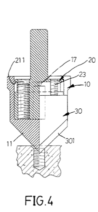
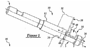
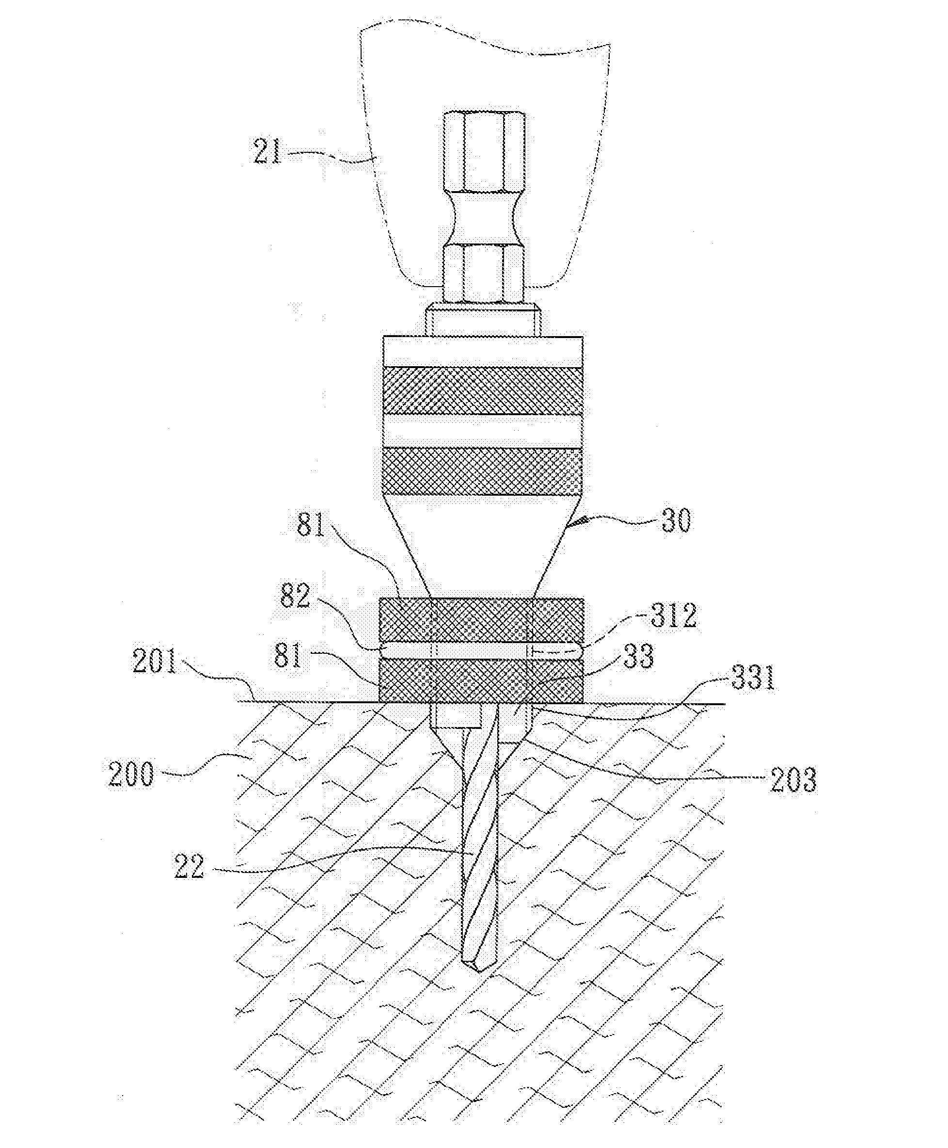
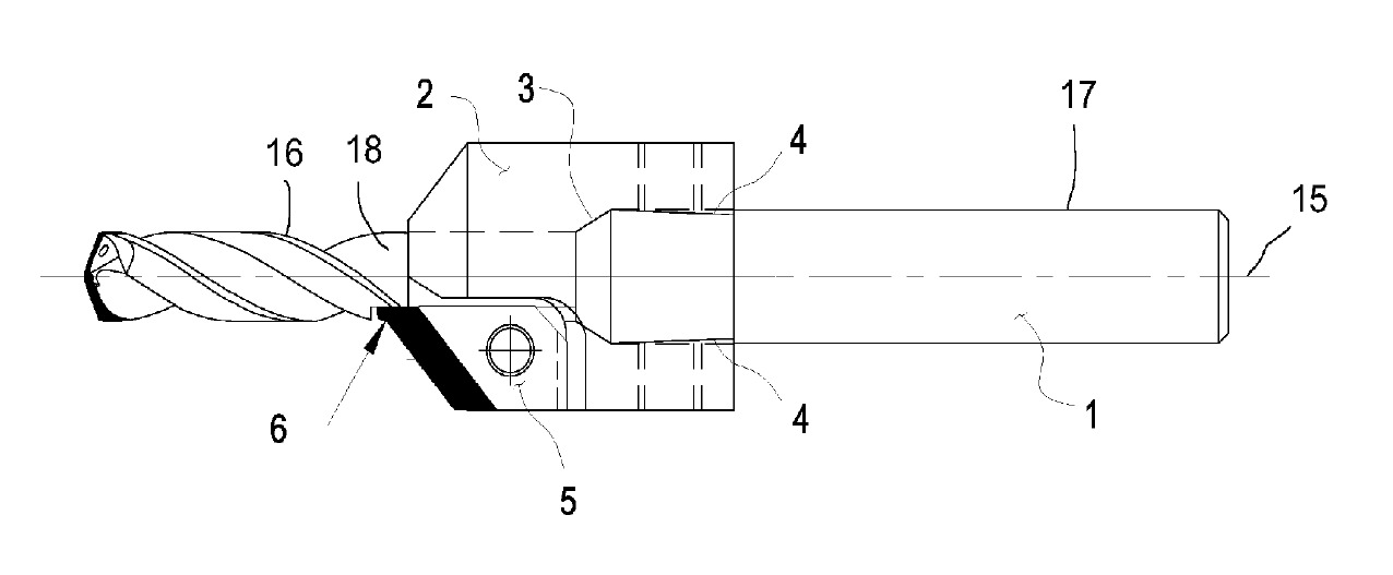
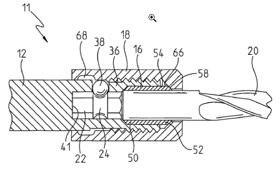
This place covers:
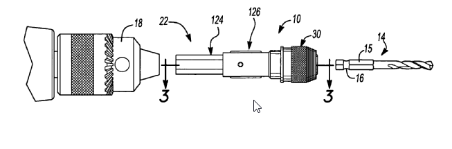
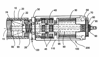
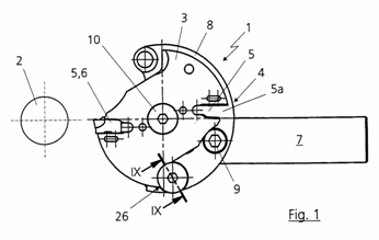
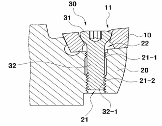
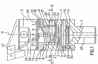
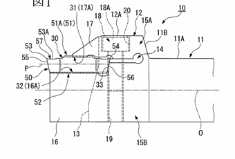
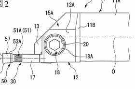
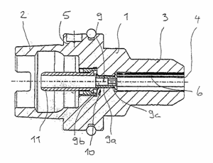
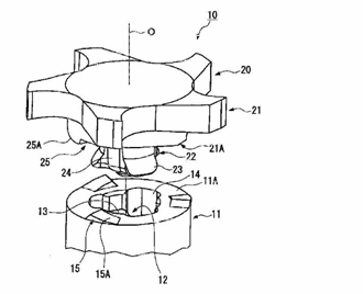
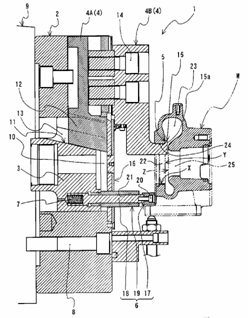
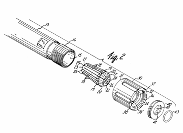
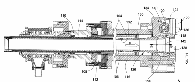
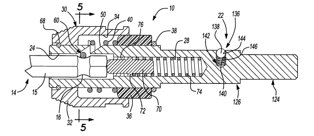
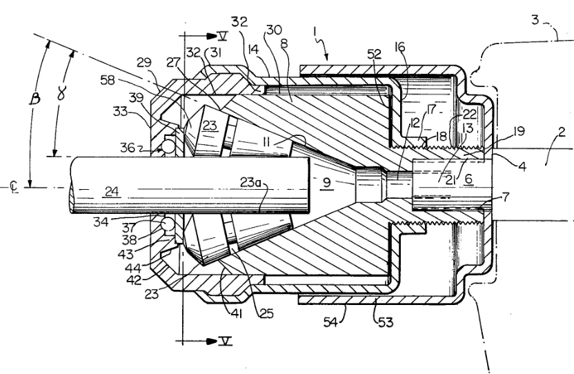
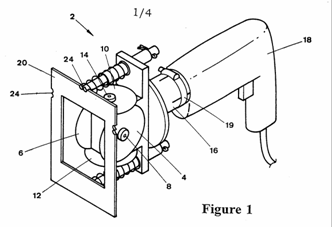
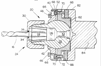
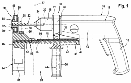
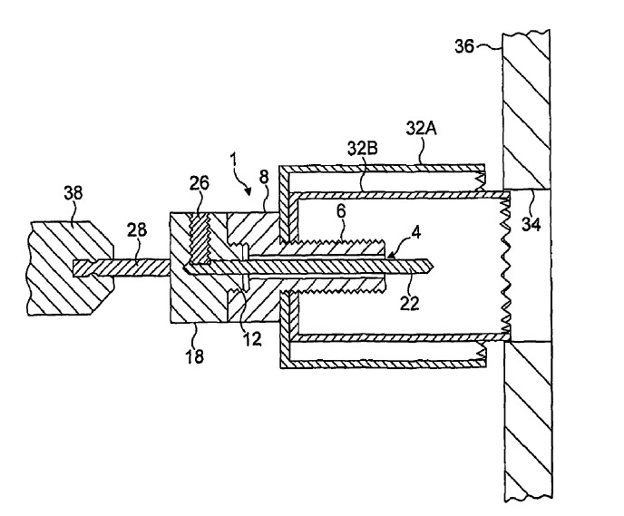
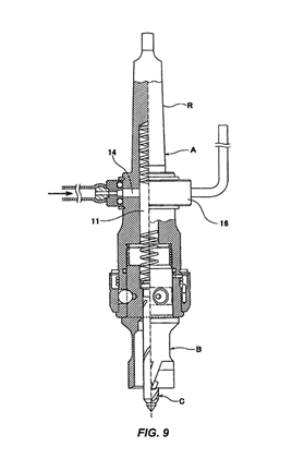
Illustrative example of subject matter classified in this group.
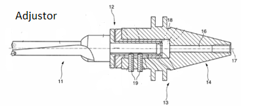
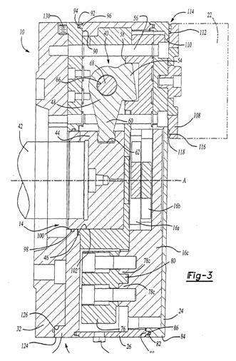
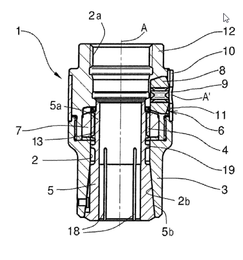
Adjustor for setting diameter of bore with rotary cutting tools. Cutting tool 11; tool holder 13; adjusting device 12; Steep taper shank 16; axis of rotation 17: receiving section 18; fastening screws 19.
This place does not cover:
Boring heads with tools moving radially | |
Holding tools yieldably | |
With means for adjusting the chuck with respect to the working spindle |
Attention is drawn to the following places, which may be of interest for search:
Devices for securing work or tools to spindles |
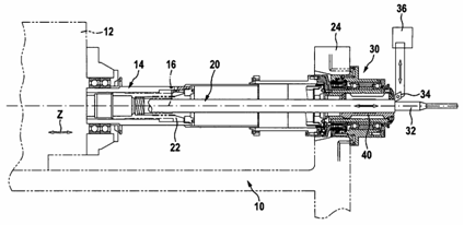
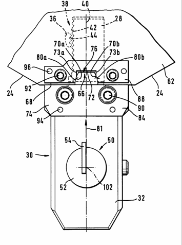
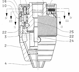
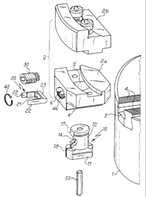
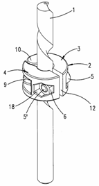
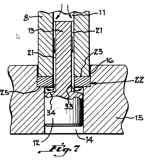
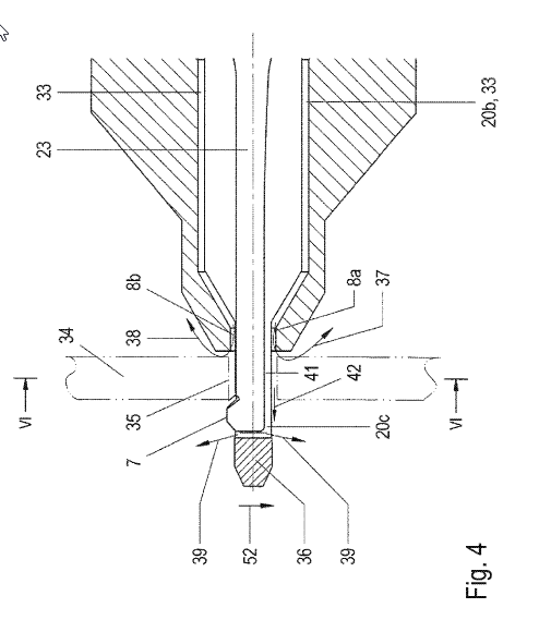
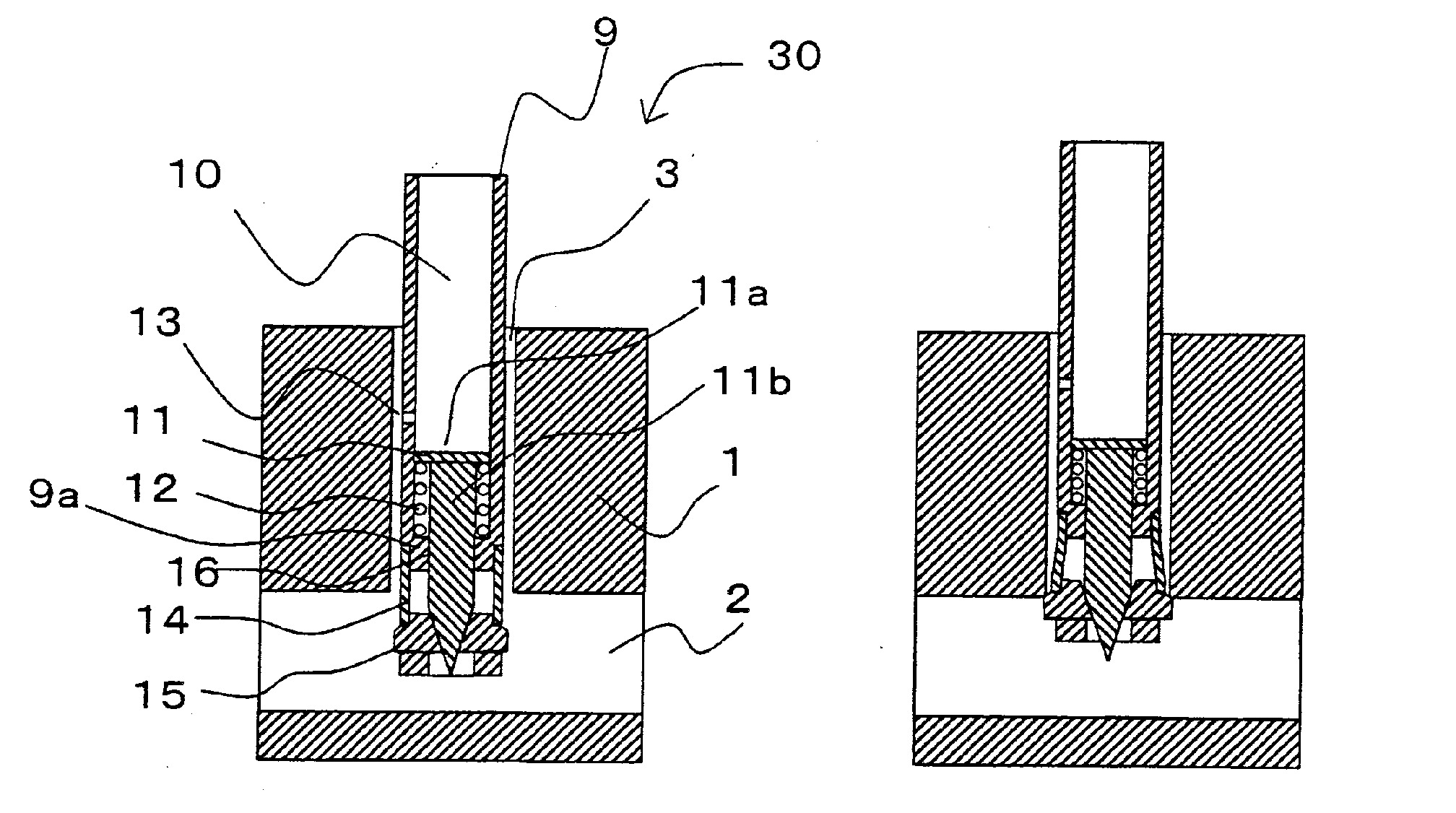
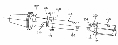
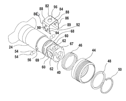
This place covers:
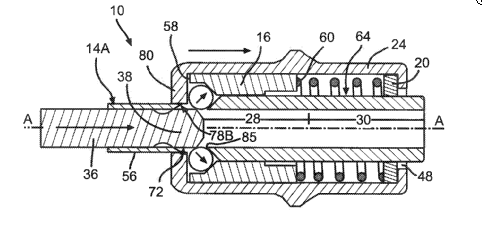
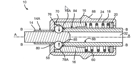
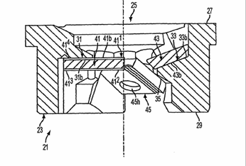
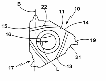
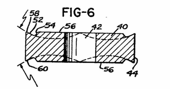
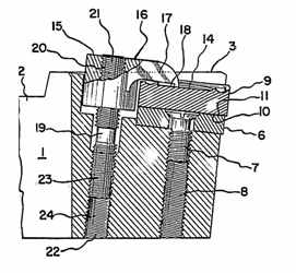
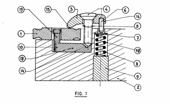
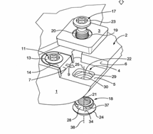
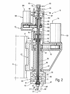
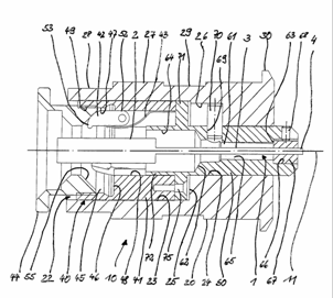
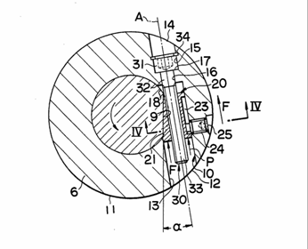
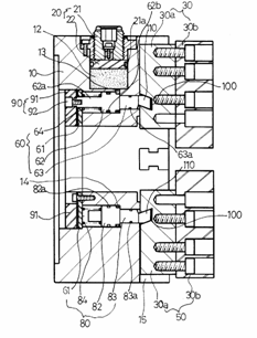
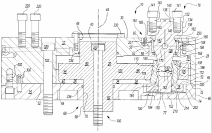
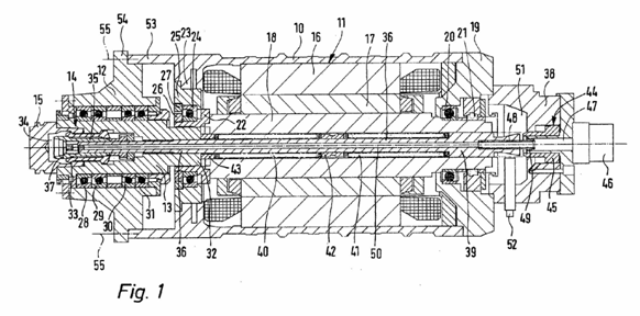
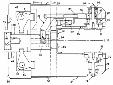
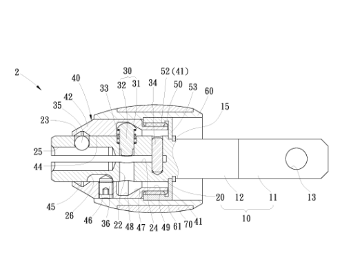
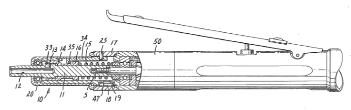
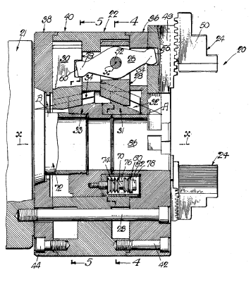
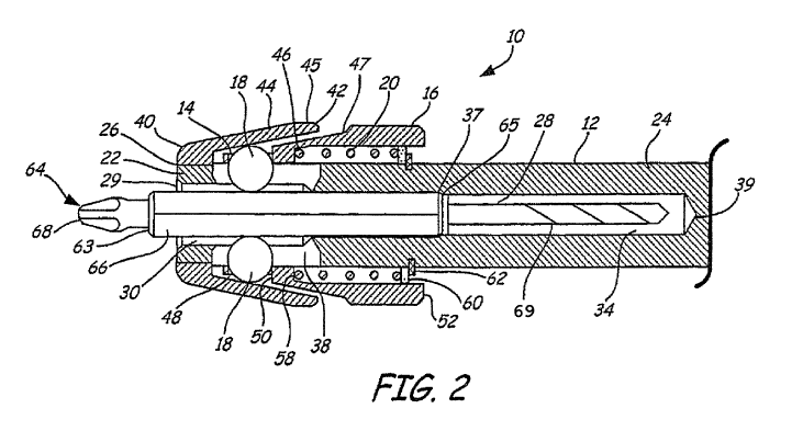
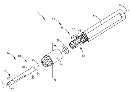
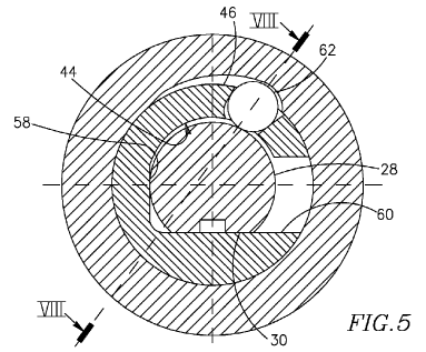
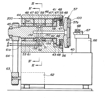
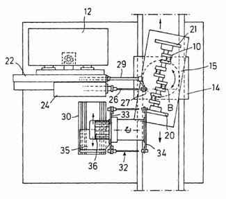
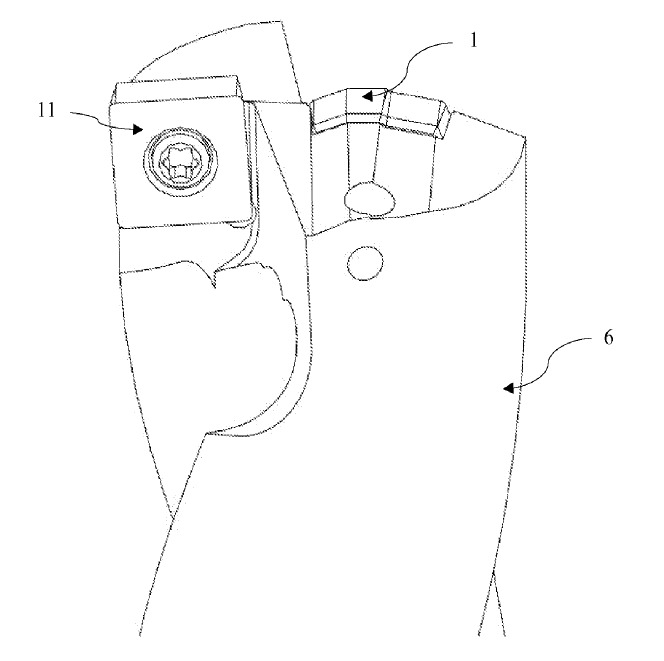
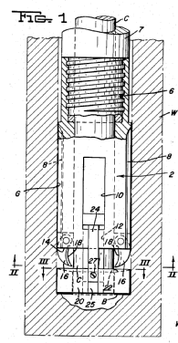
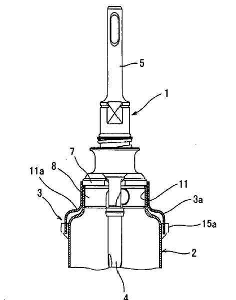
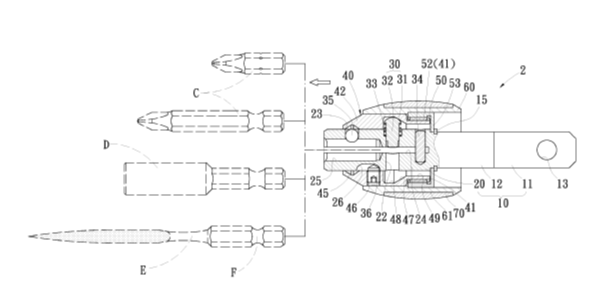
Illustrative examples of subject matter classified in this group.
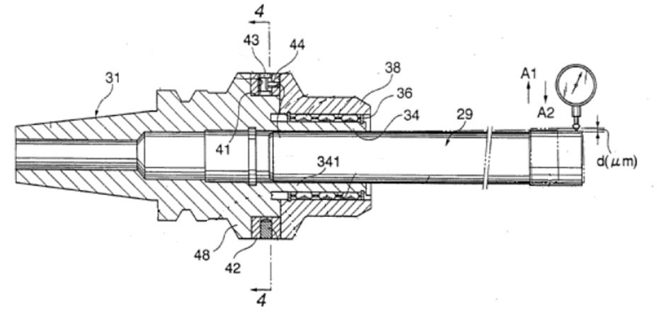
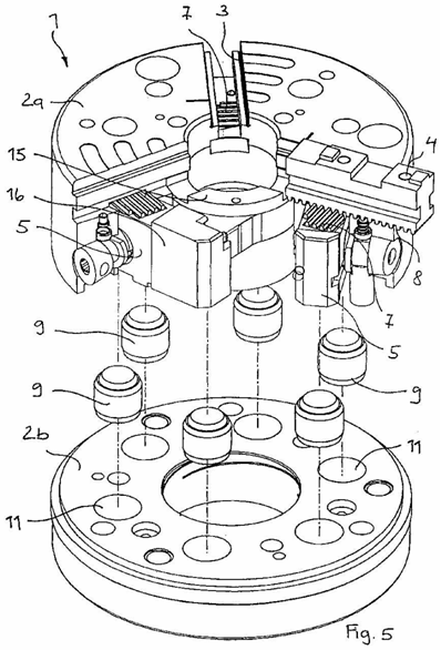
Cutting tool 29; holder body 31; base end portion 341 of the chuck sleeve 34, which is continuous with the cylindrical support portion 48; tip run-out of the cutting tool 29; rotating the eccentric cam 43 provided in the ring member 42; cylindrical support portion 48; the holder body 31; pin 44: clamp sleeve 38.
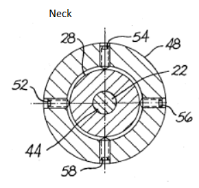
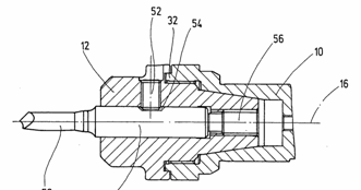
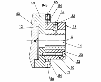
Chuck with means (52/54/56/58) for centering a tool or workpiece.
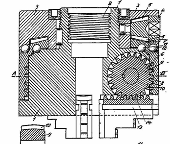
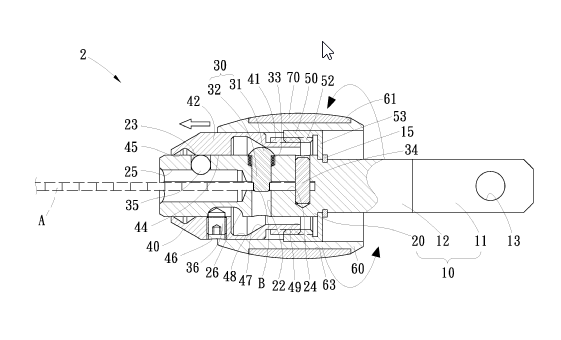
This place covers:
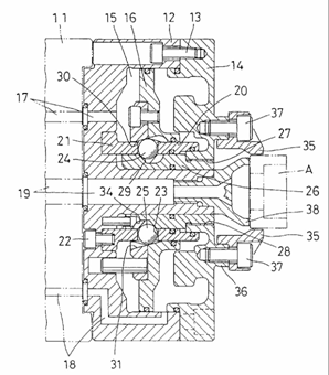
Illustrative example of subject matter classified in this group.
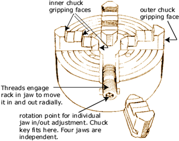
Chuck with separately acting jaws movable radially.
This place does not cover:
Chucks with simultaneously acting jaws moving radially | |
Individually adjustable jaws | B23B 31/1602, B23B 31/16062, B23B 31/161, B23B 31/16137, B23B 31/16175, B23B 31/16212, B23B 31/1625, B23B 31/16283 |
This place covers:
Illustrative example of subject matter classified in this group.
Chuck with ball detents (38). To be classified in this group, the balls should enter a groove or recess in the shank being held.
B23B 31/1071 is used for retention balls to hold the shank of the tool where the shank has a depression or groove to receive the ball.
B23B 31/22 is used for balls which form jaws in which the shank is solid and the balls that form jaws abut the outer circumference of the shank.
This place does not cover:
Balls acting as jaws |
This place covers:
Illustrative examples of subject matter classified in this group.
Chuck with axial or circumferential cylindrical detents. To be classified in this group, the cylindrical detents should enter a groove or recess in the shank being held.
B23B 31/1072 is used for cylindrical elements to hold the shank of the tool where the shank has a depression or groove to receive the cylindrical elements.
B23B 31/223 is used for cylindrical elements which form jaws in which the shank is solid and the cylindrical elements that form jaws abut the outer circumference of the shank.
This place does not cover:
Cylindrical elements acting as jaws |
This place covers:
Illustrative example of subject matter classified in this group:
Chuck with conical detents. To be classified in this group, the conical elements should enter a groove or recess in the shank being held.
B23B 31/1073 is used for conical elements to hold the shank of the tool where the shank has a depression or groove to receive the conical elements.
B23B 31/226 is used for conical elements which form jaws in which the shank is solid and the conical elements that form jaws abut the outer circumference of the shank.
This place does not cover:
Conical elements acting as jaws |
This place covers:
Illustrative examples of subject matter classified in this group.
Chuck with radial pin detent.
This place covers:
Illustrative example of subject matter classified in this group.
Chuck (14) with screw detent (36) acting on floating pin (18).
This place covers:
Illustrative example of subject matter classified in this group.
Chuck with spring or wire detent (60).
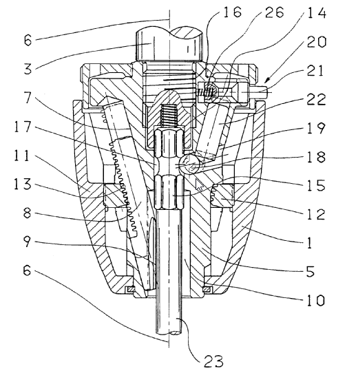
This place covers:
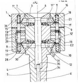
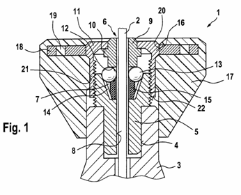
Illustrative example of subject matter classified in this group.
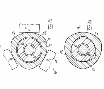
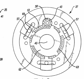
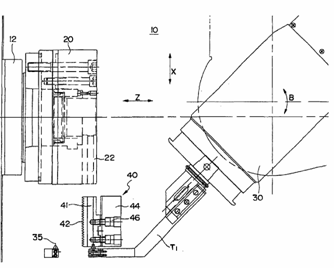
Chuck using centrifugal force to counterbalance the jaws. Action bar 26 extends substantially longitudinally of the chuck axis x, and is mounted intermediate its ends on a pivot pin 52 with an axis x'.
This place covers:
Illustrative example of subject matter classified in this group.
Chuck using centrifugal force to grip a tool or workpiece.
This place covers:
Illustrative example of subject matter classified in this group.
Collet chuck with threaded cam actuator (100).
This place covers:
Illustrative example of subject matter classified in this group.
Collet chuck with axial fixed threaded cam actuator (3) and moving jaws (5).
This place covers:
Illustrative example of subject matter classified in this group.
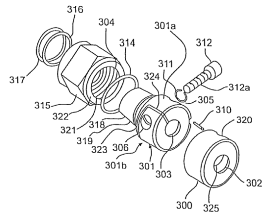
Collet chuck comprises a sleeve (301) split into two relatively movable parts (301a/301b).
This place does not cover:
Using mechanical transmission through the spindle |
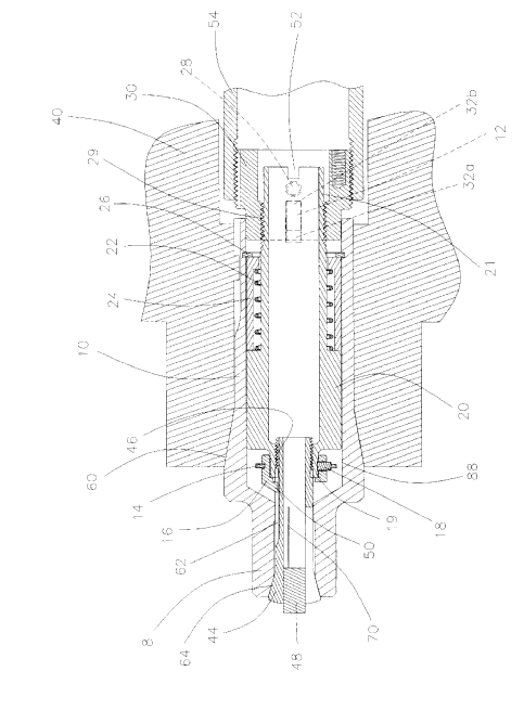
This place covers:
Illustrative example of subject matter classified in this group.
Collet chuck with reciprocating cam actuator.
This place does not cover:
Using mechanical transmission through the spindle |
This place covers:
Illustrative example of subject matter classified in this group.
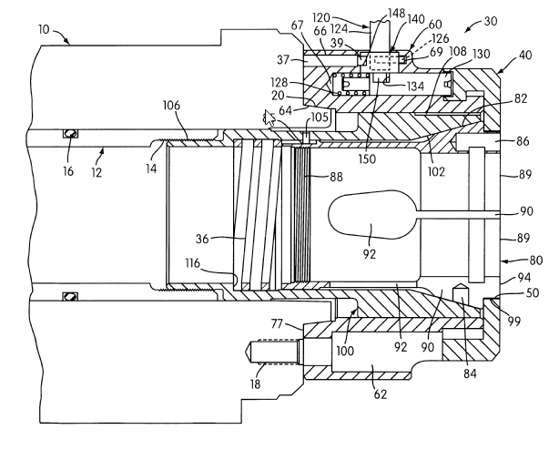
Collet chuck with axial moving cam actuator (100) and fixed jaws (89).
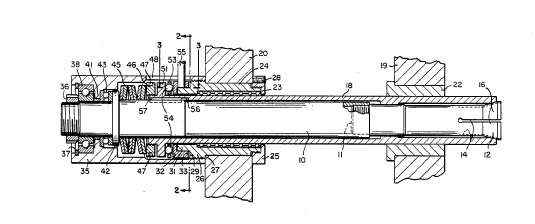
This place covers:
Illustrative example of subject matter classified in this group.
Collet chuck with axially fixed cam actuator (8) and moving jaws (44).
This place does not cover:
Axially fixed cam, moving jaws |
This place covers:
Illustrative example of subject matter classified in this group:
Chuck with balls that are used as jaws. To be classified in this group, the balls should contact a solid outer surface of the shank being held.
B23B 31/1071 is used for retention balls to hold the shank of the tool where the shank has a depression or groove to receive the ball.
B23B 31/22 is used for balls which form jaws in which the shank is solid and the balls that form jaws abut the outer circumference of the shank.
Attention is drawn to the following places, which may be of interest for search:
Retention by balls acting as detents |
This place covers:
Illustrative example of subject matter classified in this group:
Chuck with axial or circumferential cylindrical elements used as jaws. To be classified in this group, the cylindrical elements should contact a solid outer surface of the shank being held.
B23B 31/1072 is used for cylindrical elements to hold the shank of the tool where the shank has a depression or groove to receive the cylindrical elements.
B23B 31/223 is used for cylindrical elements which form jaws in which the shank is solid and the cylindrical elements that form jaws abut the outer circumference of the shank.
Attention is drawn to the following places, which may be of interest for search:
Retention by axially or circumferentially oriented cylindrical elements acting as detents |
This place covers:
Illustrative example of subject matter classified in this group:
Chuck with conical elements used as jaws. To be classified in this group, the conical elements should contact a solid outer surface of the shank being held.
B23B 31/1073 is used for conical elements to hold the shank of the tool where the shank has a depression or groove to receive the conical elements.
B23B 31/226 is used for conical elements which form jaws in which the shank is solid and the conical elements that form jaws abut the outer circumference of the shank.
Attention is drawn to the following places, which may be of interest for search:
Retention by conical elements acting as detents |
This place covers:
Illustrative example of subject matter classified in this group.
Vacuum chuck.
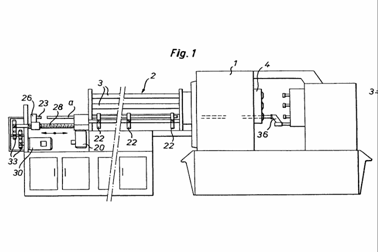
This place covers:
Drivers; driving centres and nose clutches. Drivers or driving centres are devices used to drive workpieces on lathes, when the workpiece is not held in a chuck mounted on the driving spindle, e.g when the workpiece is supported between centres or similar devices. This group does not encompass driving spindles for workpieces (see B23Q 1/70), driving or feeding mechanisms for spindles (see B23Q 5/04), driving or feeding mechanisms for static tools or tools driven in rotation (B23Q 5/04 or B23Q 5/22), or feeding mechanisms for carriages (see B23Q 5/22). Please see the table of IPC classes missing from ECLA under the main heading of B23B.
Illustrative example of subject matter classified in this group:
B23B 33/00 Lathe dog (16), (Source: US 2418864).
B23B 33/005 Driver (10) with pins (34) (Source: WO 01/76793).
Classification is generally per literal interpretation of the group and subgroup headings.
In this place, the following terms or expressions are used with the meaning indicated:
Drive dog | device used to drive a workpiece held between centres in rotation that interacts with a pin on the faceplate |
This place covers:
Methods for boring or drilling. The method must be related to the drilling or boring operation per se. The term "drilling" is intended to mean the removal of material by the rotation of a tool relative to a workpiece with the primary purpose of the efficient removal of material. In drilling to tool generally has an elongated cutting edge. The term "boring" is intended to mean the machining of an existing hole by a relative helical movement of one or more single point cutting tools with respect to the workpiece in order to either improve the surface finish of the hole or to more precisely establish the centre of the hole. A boring operation may thus remove more material from one side of a hole than from the opposite side, whereas in a drilling operation the same amount of material is removed from each side of the axis of the tool. A drilling operation generally has a higher material removal rate than a boring operation.
Documents should not be classed if they relate to merely to work holding or the workpiece being machined by known methods.
Classification is generally per literal interpretation of the group and sub-group headings.
This place covers:
Ultrasonic drilling or boring, methods and equipment for ultrasonic drilling or boring.
Illustrative example of subject matter:
B23B 37/00 Drilling using ultrasound(Source: GB 1094115).
This place covers:
Machines designed for drilling only.
Illustrative examples:
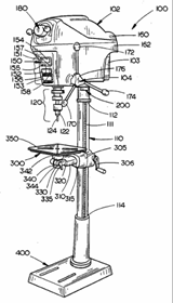
B23B 39/00 General purpose pillar drill (not systematically classified) (Source: US 2006/0104731).
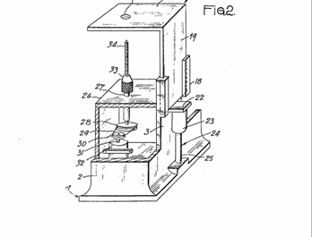
B23B 39/003 Drill with spindle situated beneath workpiece (Source: FR 1537128).
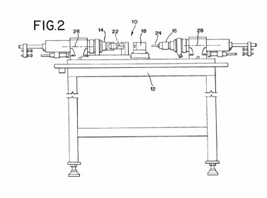
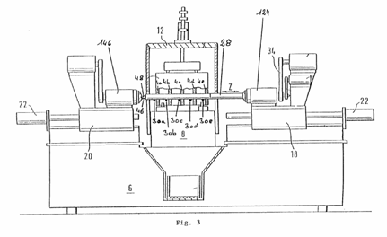
B23B 39/22 Drilling machines with opposite headstocks (Source: US 2008/0145161).
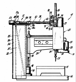
B23B 39/12 Radial drill (not systematically classified) (Source: US 4 043 700).
Most modern machine tools (e.g. horizontal boring machines and jig-boring machines) perform drilling and milling, as well as other operations and will not be classed here, being classed instead in B23Q for constructional features. Similarly, a drill with an auxiliary device for measuring, sensing or positioning the workpiece will only be classed in the group for the invention.
This place covers:
Drilling machines with multiple (including parallel) working spindles.
Illustrative example:
B23B 39/162 Multispindle drill with gears transmission between spindles
(Source: US 2004/0136797).
Since usually only drilling is possible on such machines, all such machines should be systematically classified here.
This place covers:
Drilling machines for special purpose.
Illustrative examples:
B23B 41/04 Device for drilling non-circular holes (see also B23B 51/0072) (Source: WO 00/03828).
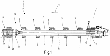
B23B 41/02 Deep hole drilling machine. Typically coolant in the form of neat oil is fed down outside of tool to cutting tips and chips and coolant are discharged through the centre of the drill tube. (Source: WO 2009/118948).
B23B 41/12 Machine for boring engine block bearing surfaces (Source: WO 98/41350).
B23B 41/12 machine for drilling oil galleries in crankshafts (Source: DE 29907963U).
Systematic classification required.
This place covers:
Drilling devices to be attached to a machine tool.
Illustrative example:
B23B 43/02 Device to allow a drill bit (16) to be fitted to a tailstock quill (84) of a lathe (Source: US 5 752 706).
This group is hardly used. Manual in nature.
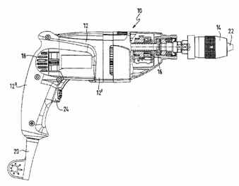
This place covers:
Hand-held or like portable drilling machines, e.g. drill guns, and equipment therefor. In order to be classified in this group the features of the hand tool must relate to the drilling operation. If a document relates to features of the hand tool, which are applicable to other hand tools (e.g. casings, handles) it should be classified only in B25F 5/00, even if it presents a hand drill as the illustrative embodiment. Documents detailing gearing should be classified in B23B 45/00 if the details of the gearing contain features relevant to the drilling operation (e.g. two speed drilling, overload clutch in case drill jams) but not if the details relate to operations other than drilling (e.g. adjustable torque clutch for screwdriving operations). Combined driver/drills should only be classed in B23B 45/02 if there are features relevant to the driling operation. Drivers are classed in B25B 21/00. Arrangements for the removalor collection of swarf (e.g. by suction) for portable drilling machines are not classified in B23B 45/00 but in B23Q 11/0042
Illustrative examples of subject matter classified in this group:
B23B 45/006 Drilling machine chuck keys (Source: US 6 488 288).
B23B 45/003 Aligning accessory for hand drill (drill stands B25H 1/0021) (Source: EP 1 897 662).
B23B 45/008 (see also B25F 5/001 for hand tools in general) Details of gearings, clutches etc. Note drill stands B25H, feed mechanisms B23Q 5/00.
(Source: DE 10316889).
Must be related to drilling operation itself to be classed here. If related to general construction of the hand tool rather than the drilling operation per se the document should be classed in B25F.
No systematic classification here for just being an electric hand drill. See notes to B23B 45/00. Electric hand drills should be classified for the features of the claimed invention.
This place covers:
Constructional details of boring or drilling machines and accessories for boring or drilloing machines.
Contrary to the IPC , documents for constructional features of drive and feed mechanisms are classified in B23Q.
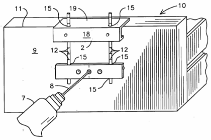
This place covers:
Drill jig.
Guides tool to a known point on workpiece.
Jig has means for location of and/or reference of the workpiece thus placing the workpiece in a repeatable position with respect to the jig.
Illustrative examples:
B23B 47/281 Pipe drill jig (Source: US 3743433).
B23B 47/287 Drill jig for plate-like workpiece (Source: US 2007/0101598).
Drill bushes are classified in B23B 49/023 and B23B 49/026.
Vacuum or blowing systems for the evacuation of drilling debris from holes is classed In B23Q 11/0042, which takes precedence. B23B 47/34 is used when the evacuation of chips from drilled holes is performed as a result of the drilling process (e.g. by virtue of feed movement or configuration of drilling tool or machine).
This place covers:
Illustrative examples of subject matter classified in this group:
B23B 49/026 Drill bush attached to workpiece by suction (Source: DE 20 2009 004 053 U).
B23B 49/023 Boring bushings (120) and their connection to template (116),
(Source: EP 2 025 439).
B23B 49/04 Devices for drilling centre holes (Source: EP 1 440 753).
B23Q 17/00 for measuring and gauging applicable to other operations and measuring or gauging on machine tools in general.
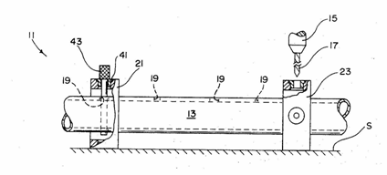
This place covers:
Stops attached to drilling tools, tool holders or drilling machines. Although most documents in this group relate to depth stops, fence-type stops particularly for drilling machines may also be classified here as they fall within the definition of the sub-group.
Illustrative examples of subject matter classified in this group:
B23B 49/005 Depth stop attached to drill bit (Source: DE 10 2007 011 289).
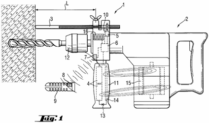
B23B 49/008 Depth stop attached to drilling machine (Source: EP 1 163 982).
This place does not cover:
Bits for countersinking with stops |
This group takes precedence over B25F 5/003 - stops for limiting depth in rotary hand tools.
This place covers:
Bushes that are attached to either a template or directly to the workpiece. In contrast to drill jigs, the drill bush must be positioned relative to the workpiece.
This place covers:
Tools for drilling machines that must be related to a drilling operation. The term "drilling'' refers to the removal of material of from a workpiece with at least one geometrically defined cutting edge of the drilling tool during rotation of the tool, relative to the workpiece, about a rotation axis thereof. Furthermore, during drilling the tool only moves axially relative to the workpiece during operation. The primary purpose of the efficient removal of material for forming or enlarging a bore or hole.
Illustrative examples of drilling tools classed within B23B 51/00 and subgroups:
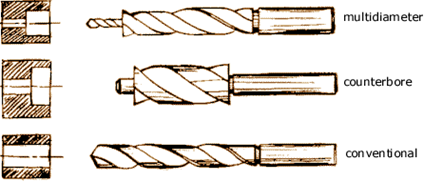
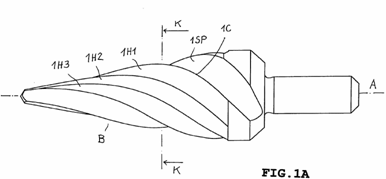
B23B 51/009 Stepped drill (top figure)
B23B 51/107 Counterboring drill with pilot (middle figure)
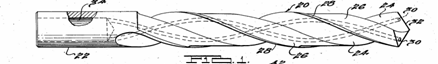
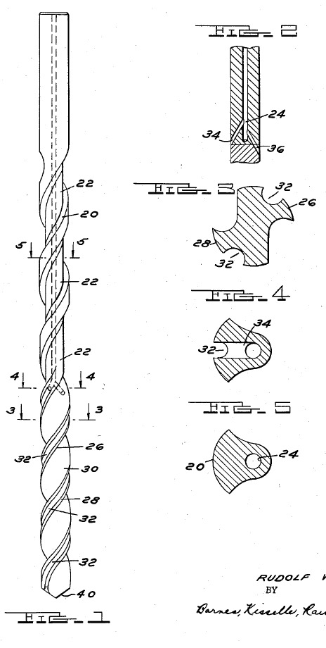
B23B 51/02 Twist drill (bottom figure)
B23B 51/00 covers features of tools specifically related to drilling of metal or metal-like materials. Features relating to the drilling of materials other than metal will only be classified in B23B if the content of such documents renders them applicable to metal cutting.
Attention is drawn to the following places, which may be of interest for search:
Drill bits for surgery | |
Drill bits for dentistry | |
Implanting tools or instruments | |
Forming collars by flow-drilling | |
Flow drills | |
Tools for orbital drilling | |
Shank-type milling cutters, i.e. with an integral shaft | |
Reaming tools | |
Making holes by electrical discharge machine or electrochemical machining | |
Boring by laser beam | |
Making drilling tools | |
Perforating tools | |
Perforating by non-mechanical means, e.g. by fluid jet | |
Wood bits that would not be suitable for use on metal or metal-like substances | |
Drill bits for drilling wood | |
Drill bits for stone or stone-like materials, e.g. brick, concrete, glass | |
Drill bits with geometrically undefined cutting edges for stone or glass materials | |
Implements for stirring paint | |
Drill bits or drill inserts characterized only by the composition of the coating | |
Drill bits for earth drilling |
Allocation of 2000-series Indexing Codes from the section B23B 2251/00 is mandatory.
Paint stirrers, yacht sail hoisters, pumps for hosepipes or other tools that are attached to a portable drilling machine as a source of power are classified in the application-oriented places.
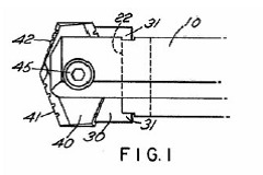
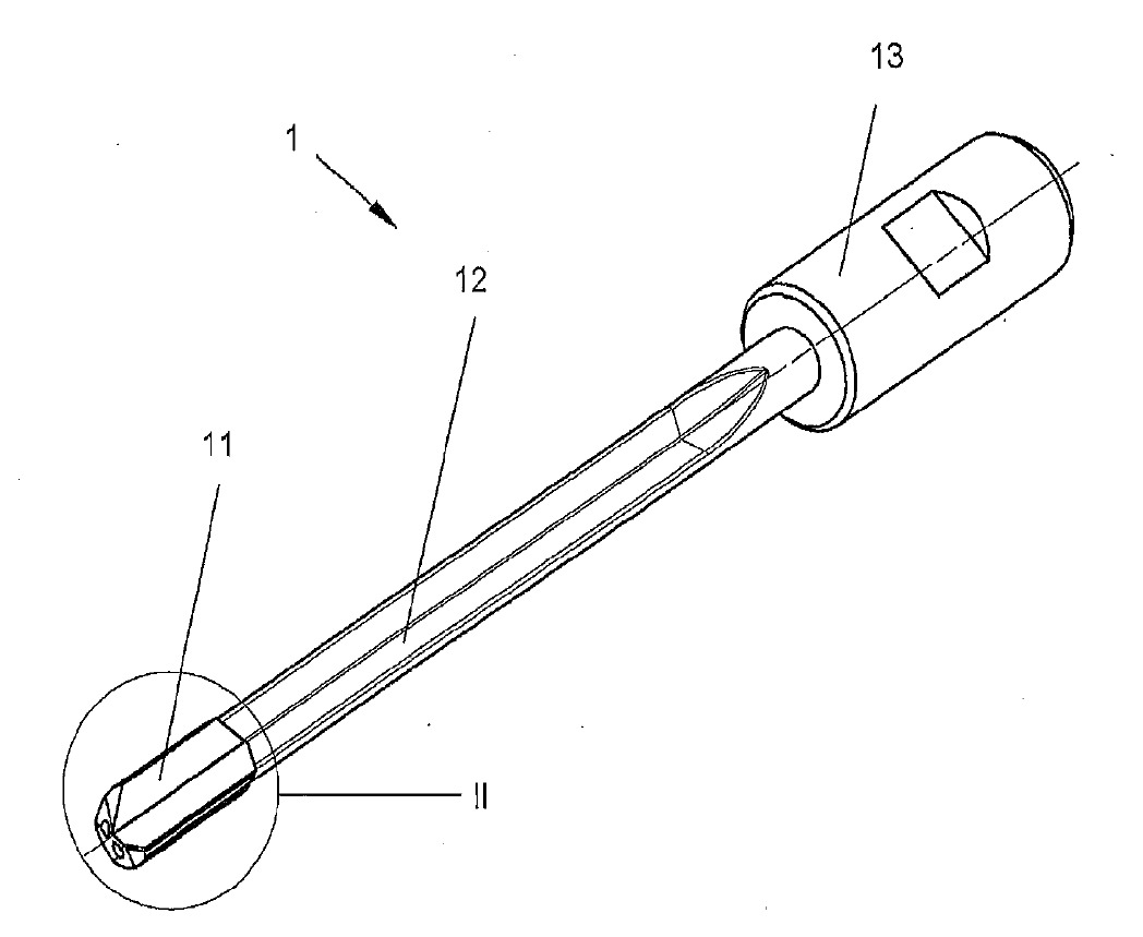
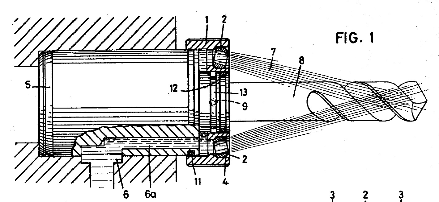
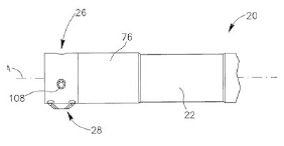
This place covers:
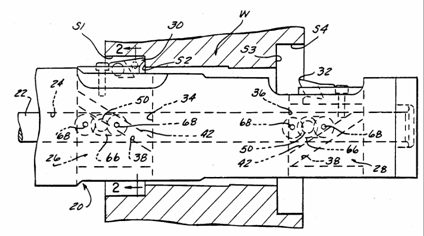
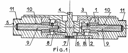
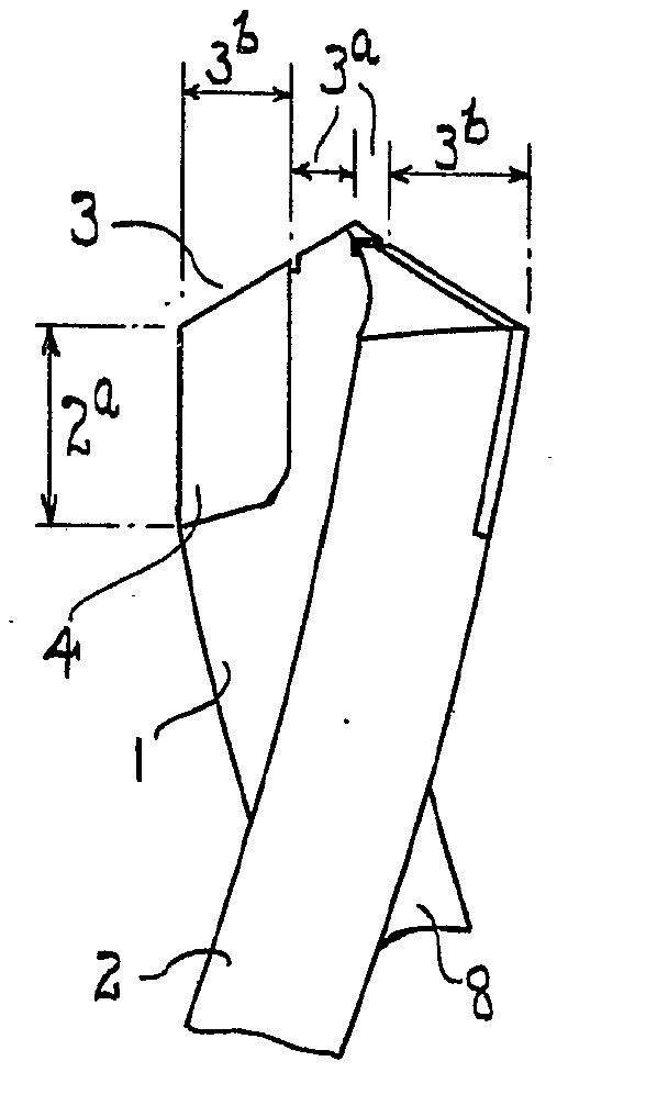
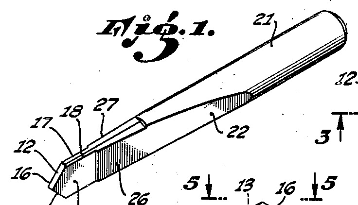
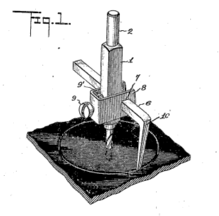
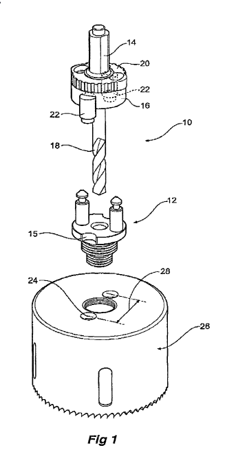
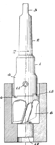
Drills with separate cutting heads permanently attached to the drill, e.g. brazing or welding. A single insert extending across the rotational axis and having at least two radially extending cutting edges in the working position is considered to be within the scope of this group.
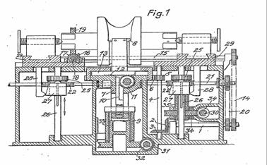
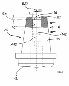
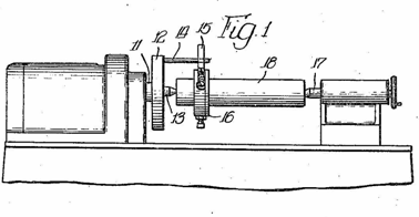
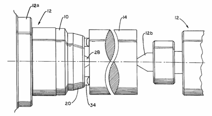
Illustrative example of subject-matter classified in this group:
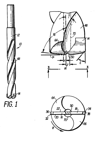
The drill 10 comprises a steel shank 12 and a carbide tip 14 brazed in the end of the shank (see Fig.1).
Attention is drawn to the following places, which may be of interest for search:
Drill bits with other types of cutting inserts |
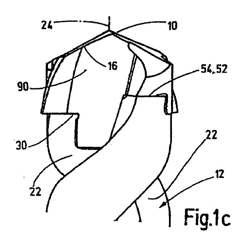
This place covers:
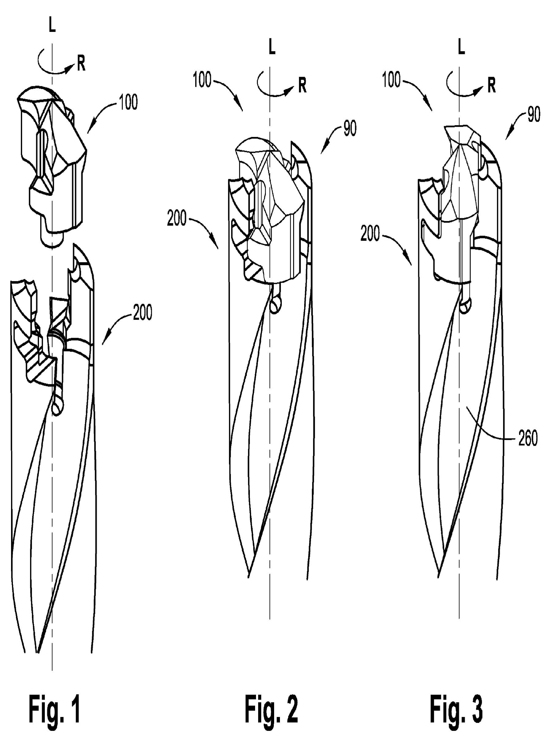
Drills with separate cutting heads removably attached to the drill. A single insert extending across the rotational axis and having at least two radially extending cutting edges in the working position is considered to be within the scope of this group.
Illustrative example of subject-matter classified in this group:
Attention is drawn to the following places, which may be of interest for search:
Drill bits with other types of cutting inserts |
This place covers:
Drills with a removable insert having a flat spade configuration, which includes a centre tip cutting edge and two radially extending cutting edges.
Illustrative example of subject-matter classified in this group:
Attention is drawn to the following places, which may be of interest for search:
Drill bits with other types of cutting inserts | |
Other spade drill bits |
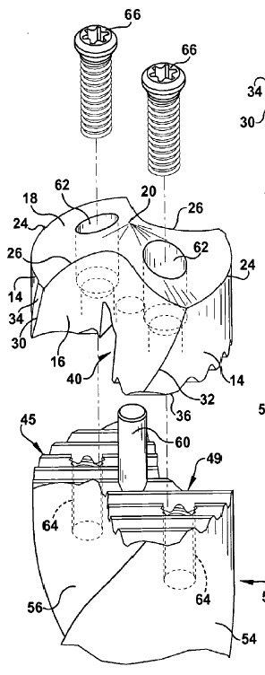
This place covers:
Drills with separate cutting heads removably attached to the drill by screw means. A single insert extending across the rotational axis and having at least two radially extending cutting edges in the working position is considered to be within the scope of this group when it is attached via screw means.
Illustrative example of subject-matter classified in this group:
Attention is drawn to the following places, which may be of interest for search:
Drill bits with other types of cutting inserts |
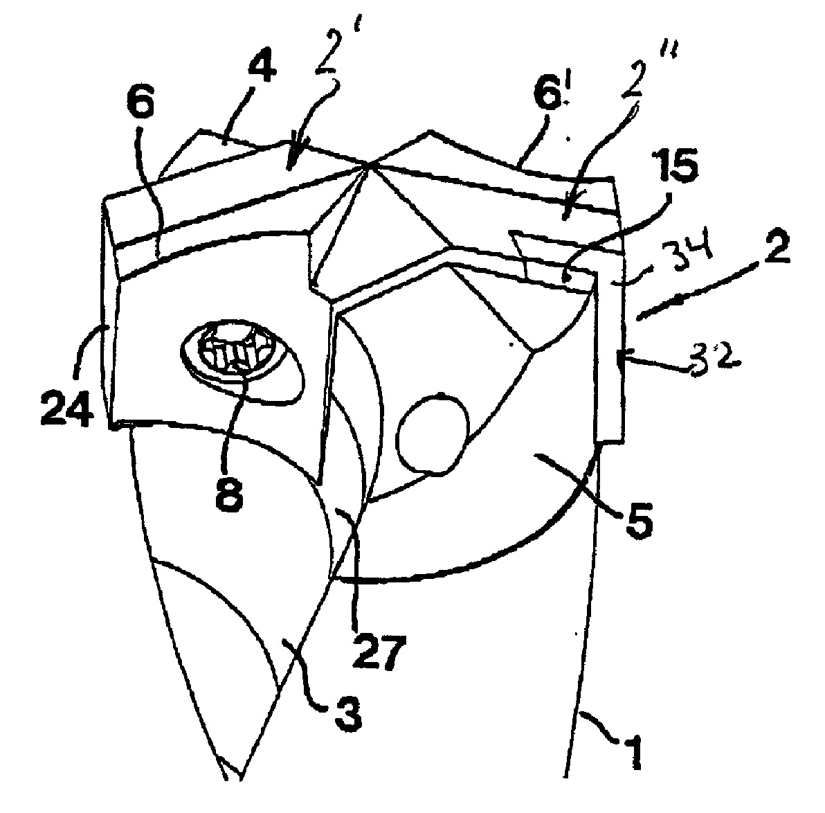
This place covers:
Drills with separate cutting heads removably attached to the drill by wedge means (i.e., producing a wedging effect between the separate cutting head and the shank of the drill). A single insert extending across the rotational axis and having at least two radially extending cutting edges in the working position is considered to be within the scope of this group via a wedging action.
Illustrative example of subject-matter classified in this group:
Attention is drawn to the following places, which may be of interest for search:
Drill bits with other types of cutting inserts |
This place covers:
Drills with non-exchangeable cutting inserts, e.g. via brazing or welding.
Illustrative example of subject-matter classified in this group:
This place does not cover:
Drills with a single insert extending across the rotational axis and having at least two radially extending cutting edges in the working position |
Attention is drawn to the following places, which may be of interest for search:
Cutting tools of which the bits or tips (or cutting inserts) are of special material | |
Cutting inserts for milling | |
Cutting inserts for reaming |
Allocation of 2000 series Indexing Codes from the section B23B 2200/00 is mandatory.
This place covers:
Drills with exchangeable cutting inserts.
Illustrative example of subject-matter classified in this group:
Attention is drawn to the following places, which may be of interest for search:
Drills with a single insert extending across the rotational axis and having at least two radially extending cutting edges in the working position |
Allocation of 2000-series Indexing Codes from the section B23B 2200/00 is mandatory.
This place covers:
Drills with indexable cutting inserts.
An indexable cutting insert has multiple cutting edges. After one cutting edge is worn, the indexable cutting insert can be rotated about an indexing axis or turned over to make available another cutting edge in the working position.
Illustrative example of subject-matter classified in this group:
Attention is drawn to the following places, which may be of interest for search:
Drills with a single insert extending across the rotational axis and having at least two radially extending cutting edges in the working position |
Allocation of 2000-series Indexing Codes from the section B23B 2200/00 is mandatory.
This place covers:
Drills with cutting inserts set at different radial distances from the rotation axis.
Illustrative example of subject matter classified in this group:
Attention is drawn to the following places, which may be of interest for search:
Drills with a single insert extending across the rotational axis and having at least two radially extending cutting edges in the working position |
This place covers:
Drills for enlarging a hole without enlarging the hole's opening to provide an undercut or reverse taper. Very common when drilling foundations.
Illustrative example:
B23B 51/0045 Drill for enlarging a hole (at a distance from surface) by expanding the tool head(Source: WO 93/16291).
This place covers:
centre drills.
Illustrative example of subject matter classified in this group:
B23B 51/0063 Centre drill (Source: JP 2-100807).
This place covers:
Drills for making non-circular holes.
Illustrative example of subject matter classified in this group.
B23B 51/0072 Drill for making non circular hole (see also B23B 41/04) (Source: US 3 803 980).
This place covers:
Conical drills
Illustrative example of subject matter classified in this group.
B23B 51/0081 Conical drill, (Source: DE 20 2006 019 580 U).
This place covers:
Monolithic drills that have a generally flat spade configuration in the cutting portion, which includes a centre tip cutting edge and two radially extending cutting edges. These drills are also commonly referred to as paddle bits.
Illustrative example of subject-matter classified in this group:
This place does not cover:
Spade drills with exchangeable heads or inserts |
Attention is drawn to the following places, which may be of interest for search:
Bits for woodworking |
This place covers:
Drills having a cutting portion smaller than one millimetre in diameter.
Illustrative example of subject matter classified in this group:
Examples of places where the subject matter of this place is covered when specially adapted, used for a particular purpose, or incorporated in a larger system:
Drills for printed circuits |
Attention is drawn to the following places, which may be of interest for search:
Drilling machines for very small holes |
Use of 2000-series Indexing Codes from the section "details of drilling tools", i.e. B23B 2251/00 is mandatory.
Definitions for features altering along the length of the drill are always considered starting from the tip of drill and progressing towards the shank.
This place covers:
Drills for cutting a disc or cylindrical core from a workpiece.
Note: Commonly, but not exclusively, drills for trepanning are drills with cutting edges arranged annularly about an open end of a tubular body. These drills are also known as hole saws, core drills and plug cutters.
Illustrative examples of subject matter classified in this group:
B23B 51/05: Drills for trepanning for cutting discs from sheet
Attention is drawn to the following places, which may be of interest for search:
Cylinder saws for trepanning wood that would not be suitable for use on metal or metal-like substances | |
Cylinder saws for trepanning stone or glass and having their cutting rim equipped with abrasive particles |
This place covers:
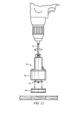
Drills for trepanning with stepped tubular cutting bodies.
Illustrative example of subject-matter classified in this group:
This place covers:
Means for cutting off a cylindrical core, e.g. a cutter axially spaced from the trepanning cutting edges for cutting off.
Illustrative example of subject-matter classified in this group:
This place covers:
Drills for trepanning including a chamfer cutter or spot bore (also referred to as counterbore) cutter.
Illustrative example of subject-matter classified in this group:
This place covers:
Trepanning drills including cooling or lubricating means.
Illustrative example of subject-matter classified in this group:
This place covers:
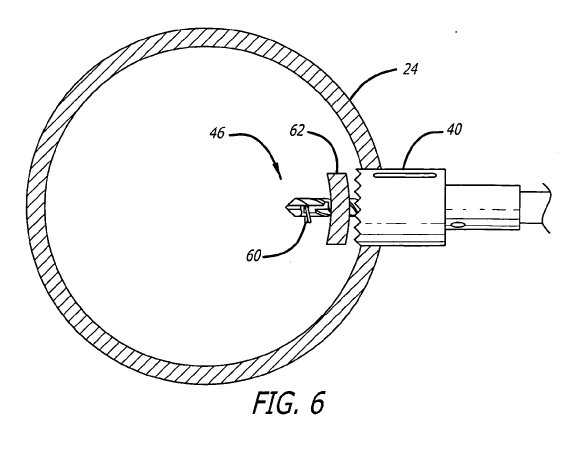
Trepanning drills including means for centering the drill relative to a new, e.g. a pilot drill, or existing hole, e.g. an attachment that engages an existing hole.
Illustrative example of subject-matter classified in this group:
This place covers:
Trepanning drills with devices for holding core relative to the drill such that the core is removed when the drill is removed.
Illustrative example of subject-matter classified in this group:
This place covers:
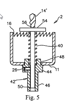
Trepanning drills with devices for ejecting the core or slug from the interior of the drill.
Illustrative example of subject-matter classified in this group:
This place covers:
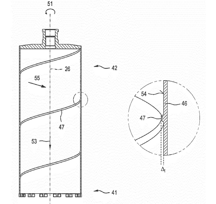
Details of the tubular body sidewall of drills for trepanning.
Illustrative example of subject-matter classified in this group:
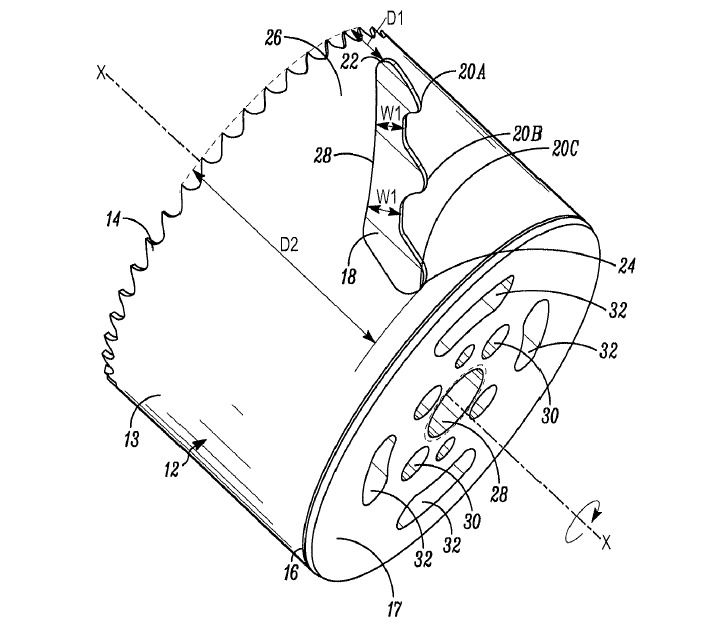
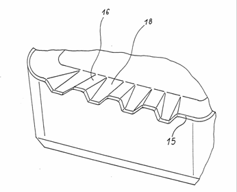
This place covers:
Details of internal grooves of the tubular body sidewall of drills for trepanning.
Illustrative example of subject-matter classified in this group:
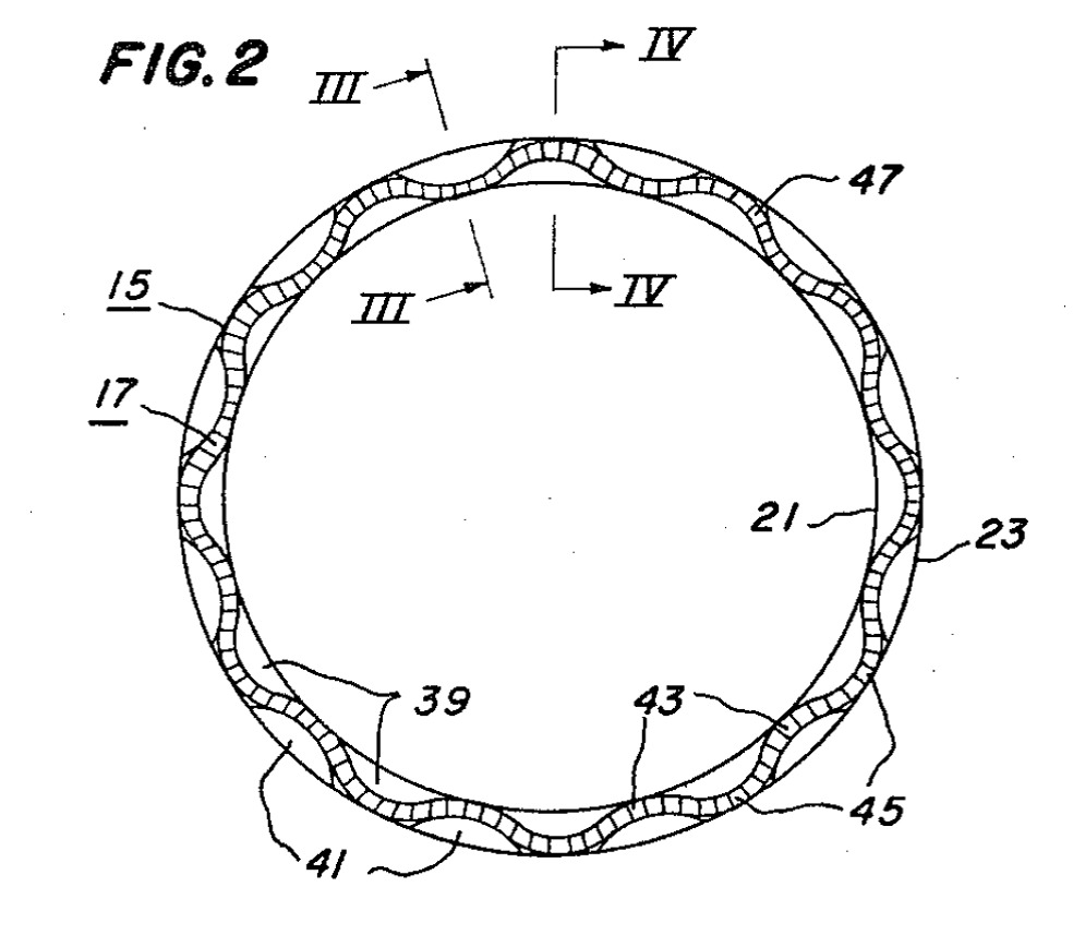
This place covers:
Details of eccentric or non-circular tubular body sidewalls of drills for trepanning.
Illustrative example of subject-matter classified in this group:
This place covers:
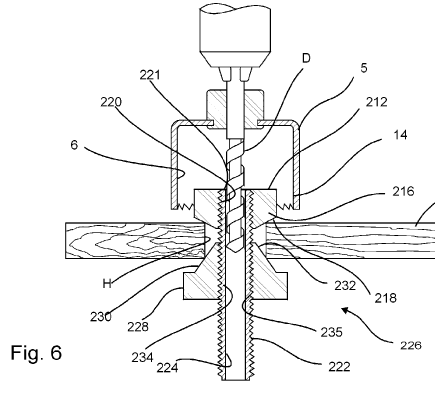
Details of connections between the driven shaft (e.g., spindle or arbor) and the tubular cutting part.
Illustrative example of subject-matter classified in this group:
This place covers:
Trepanning tools proper, i.e. tools particularly for removing material from the work by forming an annular trench therein, which trench is made progressively deeper as the tool proceeds, thereby leaving a disc. These tools have few teeth.
This place covers:
Drilling tools in which the cooling or lubricating means are of primary importance (i.e. drilling tools which have special cooling or lubricating means).
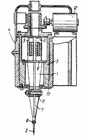
Illustrative example of subject matter classified in this group:
B23B 51/06 Drill with cooling equipment
Drilling tools having lubricating means that are not of special significance can be allocated the indexing code B23B 2250/12.
This place does not cover:
Drills for trepanning with lubricating or cooling equipment |
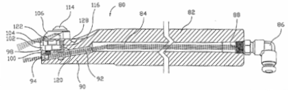
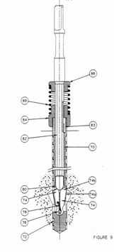
This place covers:
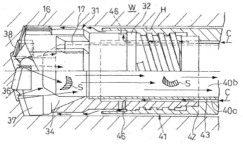
Deep hole drills for producing new as well as for machining of existing bore holes. Deep bore holes refer to bore holes that are machined by classical deep hole drilling methods and/or drilling methods with a length-to-diameter ratio larger than 10. The classical deep hole drilling methods are single-lip gun drilling (B23B 51/066) and drilling with a single-tube or double-tube system (B23B 51/063).
Illustrative example of subject-matter classified in this group:
In the single-tube system (STS or BTA system), the cooling lubricant is introduced from outside under pressure in an annular space between the bore wall and the boring bar while the chips are removed through the die chip mouth and the boring bar.
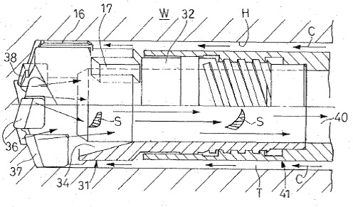
In the double-tube system (DTS or ejector system), the cooling lubricant is introduced via an annular space between the boring bar and an inner tube. The cooling lubricant exits at the side of the drill head, flows around it and then back out up the inner tube together with the chips. A part of the cooling lubricant is guided into the inner tube via a concentric nozzle. The underpressure at the chip mouth makes the return flow possible (ejector effect).
Attention is drawn to the following places, which may be of interest for search:
Boring or drilling machines for boring deep holes |
This place covers:
Gun drills.
Illustrative example of subject-matter classified in this group:
In the classical single-lip gun drill, the cooling lubricant is delivered through one or more holes, which pass through the tool shank. The mixture of chips and cooling lubricant is removed along a single straight flute or longitudinal groove (bead) on the outside of the tool shank. 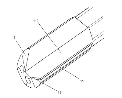
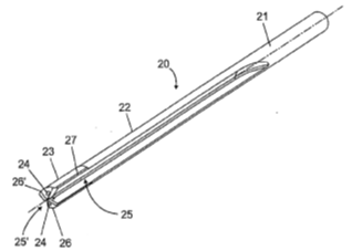
In the double-lip gun drill, the cooling lubricant passes through the tool shank and the mixture of chips and cooling lubricant is removed along two symmetrical straight flutes on the outside of the tool shank.
Attention is drawn to the following places, which may be of interest for search:
Boring or drilling machines for boring deep holes, e.g. in gun or rifle barrels |
This place covers:
Drilling tools in which the details of the cooling or lubricating channel(s) are of importance.
Illustrative example of subject-matter classified in this group:
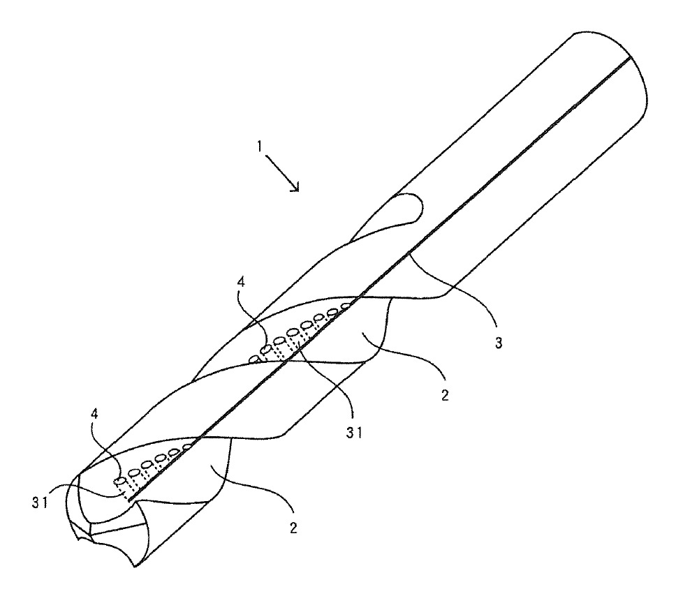
This place covers:
Drills with lubricating or cooling equipment, wherein coolant moves along outside of tool periphery toward cutting edges.
Illustrative example of subject-matter classified in this group:
This place covers:
Drills with lubricating or cooling equipment with deflector or nozzle on to point direct the coolant in a desired direction.
Illustrative example of subject-matter classified in this group:
This place covers:
Details of the cross-sectional shape of coolant hole(s).
Illustrative example of subject matter classified in this group:
This place covers:
Bits for cutting processes used in the finishing of holes including countersinking, counterboring, chamfering, deburring and spot facing.
Illustrative examples of subject matter classified in this group:
Attention is drawn to the following places, which may be of interest for search:
Deburring by milling | |
Deburring by scraping | |
Deburring by grinding |
This place covers:
Tools for removing burrs by smoothing of rough edges or ridges of a hole.
Illustrative example of subject-matter classified in this group:
Deburring drill with insert "28"
This place covers:
Tools for removing burrs by smoothing of rough edges or ridges of a hole.
Illustrative example of subject-matter classified in this group:
Back spot facing drill
This place covers:
Physical feature for stopping the axial movement of the drill at a desired depth.
Illustrative example of subject-matter classified in this group:
Chamfer drill with depth stop
This place covers:
Tools for removing burrs from edges or ridges of a hole crossing the hole in which the tool is inserted. Also, tools for enlarging the rim of such crossing hole, especially by chamfering or bevelling.
Illustrative example of subject matter classified in this group:
Tool to deburr radial holes
This place covers:
Illustrative example of subject matter classified in this group:
Chamfering tool with cutting edge moving obliquely to the axis
Examples of places where the subject matter of this place is covered when specially adapted, used for a particular purpose, or incorporated in a larger system:
Deburring by milling | |
Thermal deburring | |
Deburring by scraping | |
Deburring by grinding |
Attention is drawn to the following places, which may be of interest for search:
Bevelling, chamfering, or deburring the ends of bars or tubes |
This place covers:
Bits for countersinking having a centering drill axially forward of the countersinking cutting edges.
Illustrative example of subject-matter classified in this group:
Attention is drawn to the following places, which may be of interest for search:
Drills for trepanning including chamfer or spot bore cutter |
This place covers:
Bits for countersinking having a centering drill and a countersink in the form of an attachment to the drill.
Illustrative example of subject-matter classified in this group:
This place covers:
Illustrative example of subject-matter classified in this group:
This place does not cover:
Back spot-facing or back chamfering tools |
This place covers:
Adapters or chucks specifically for drilling bits otherwise document will be classed in B23B 31/00. Taper sleeves.
Illustrative examples:
B23B 51/123 Conical reduction sleeve(Source: NL 6617411).
B23B 51/126 Drill elongation device(Source: US 2009/0092455).
B23B 51/14 Adapters for broken drills(Source: US 2361683).
This place covers:
Illustrative examples of subject matter classified in this group.
Drill chuck with hard-metal insert 11.
This place covers:
Illustrative examples of subject matter classified in this group.
Jaws with elastomeric material 42.
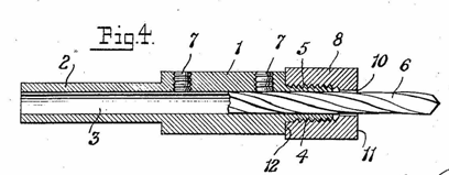
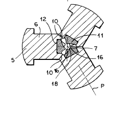
This place covers:
Illustrative examples of subject matter classified in this group.
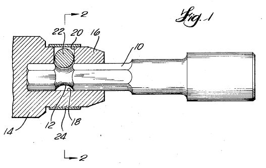
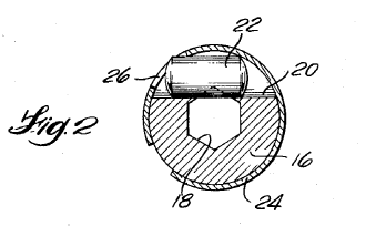
Tool retaining or connecting device: bit detent ball: 17 and 38.
Bitholder Ball 38 and collet 16.
Drill for smooth and hex-shank bits. Jaws 8, ball 18.
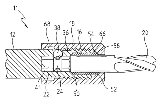
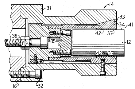
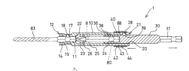
This place covers:
Illustrative examples of subject matter classified in this group.
Chucks; items 54 and 90.
Note items 30 and 35 in both illustrations above.
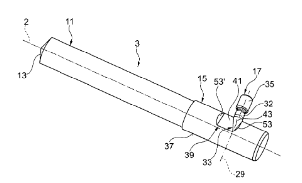
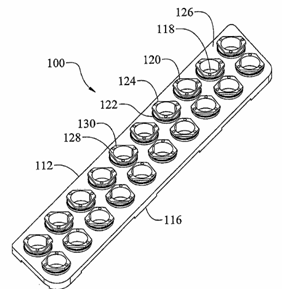
This place covers:
Illustrative examples of subject matter classified in this group.